Page 4551 of 5267
BODY VENT
REMOVAL
1. Remove the rear cab trim panel (Refer to 23 -
BODY/INTERIOR/REAR CAB BACK PANEL TRIM
- REMOVAL)
2. Disengage the retaining tabs (1) that secure the
body vent (3) to the cab back panel (2).
3. Remove the vent through the opening in the cab
back panel.
INSTALLATION
1. Position the body vent (3) into the opening of the
cab back panel (2).
2. Install the body vent into the cab back panel and
fully engage the retaining tabs (1).
3. Install the rear cab trim panel (Refer to 23 - BODY/
INTERIOR/REAR CAB BACK PANEL TRIM -
INSTALLATION).
Page 4564 of 5267
INSTALLATION
NOTE: Free pivot hinge cover is installed with the
free pivot hinge (Refer to 23 - BODY/SEATS/CEN-
TER SEAT BACK HINGE - INSTALLATION).
1. Position the hinge cover (1) over the hinge (2) and
close over the lock tabs (3).
2. Install the pivot bolt (5) and tighten to 10 Nꞏm (89
in. lbs.).
3. Reposition the storage bin/cushion cover (4).
4. Connect the zip strip (1).
Page 4596 of 5267
6. Set glass (1) on lower fence and move glass for-
ward into opening.
7. Firmly push glass (1) against rear window glass
opening fence.
8. Bend tabs around edges of backlite opening fence
to retain glass.
9. Clean excess urethane from exterior with MOPAR
,
Super Clean or equivalent.
10. Allow urethane to cure at least 24 hours (full cure
is 72 hours).
11. Water test to verify repair before returning vehicle
to service.
12. Connect the rear window defogger electrical con-
nector, if equipped.
13. On standard cab models, install the upper b-pillar
trim (5) (Refer to 23 - BODY/INTERIOR/B-PILLAR
UPPER TRIM - INSTALLATION).
14. On quad cab models, install the upper c-pillar trim
(5) (Refer to 23 - BODY/INTERIOR/C-PILLAR
UPPER TRIM - INSTALLATION).
Page 4619 of 5267
COVER-GUIDE MECHANISM
REMOVAL
1. Move the glass panel to the full closed position.
2. Slide sunshade rearward to the open position.
3. Separate the mechanism covers (2) from the tabs
(1) on the glass panel.
4. Hold both mechanism covers down and open the
sunroof fully.
5. Slide the mechanism covers (1) out the front of the
guide in the frame (2).
Page 4623 of 5267
GLASS
REMOVAL
1. Move the glass panel to the full closed position.
2. Slide sunshade rearward to the open position.
3. Separate the mechanism covers (2) from the tabs
(1) on the glass panel.
4. Remove the glass panel screws (3).
5. Lift off glass panel and remove from vehicle.
Page 4624 of 5267
INSTALLATION
1. Position glass panel on to mechanism lift arms.
CAUTION: Verify that the retaining tabs are located on the INSIDE of the guide mechanism arms.
2. Start the attaching screws (3).
3. Connect a 12v power supply and verify that the sunroof is in the closed position.
4. Adjust sunroof glass to fit flushwith roof line (Refer to 23 - BODY/SUNROOF/GLASS PANEL - ADJUSTMENTS).
5. Tighten the screws (3) to 3.5 Nꞏm (30 in. lbs.).
6. Position the mechanism covers (2) over the glass tabs (1) between the locating features and seat fully.
7. Verify sunroof operation and alignment.
Page 4625 of 5267

ADJUSTMENTS
ADJUSTMENT
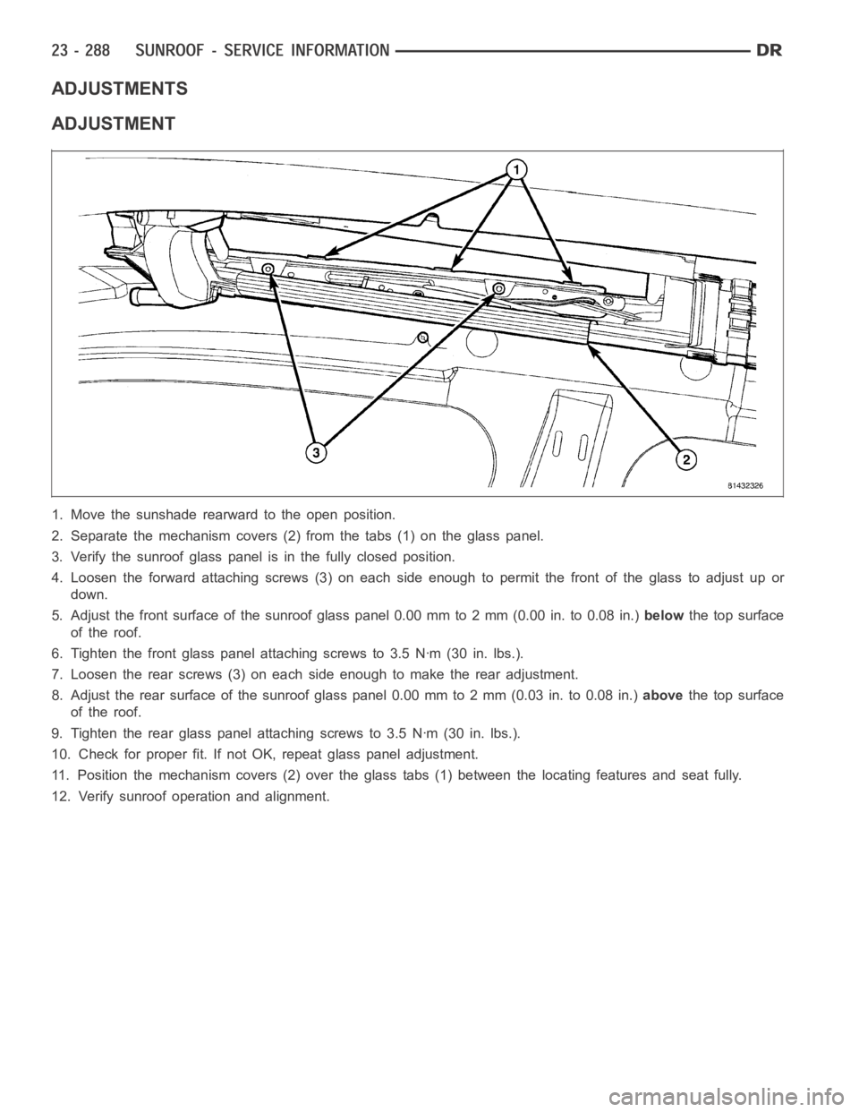
1. Move the sunshade rearward to the open position.
2. Separate the mechanism covers (2) from the tabs (1) on the glass panel.
3. Verify the sunroof glass panel is in the fully closed position.
4. Loosen the forward attaching screws (3) on each side enough to permit thefront of the glass to adjust up or
down.
5. Adjust the front surface of the sunroof glass panel 0.00 mm to 2 mm (0.00 in.to0.08in.)belowthe top surface
of the roof.
6. Tighten the front glass panel attaching screws to 3.5 Nꞏm (30 in. lbs.).
7. Loosen the rear screws (3) on each side enough to make the rear adjustment.
8. Adjust the rear surface of the sunroof glass panel 0.00 mm to 2 mm (0.03 in.to 0.08 in.)abovethe top surface
of the roof.
9. Tighten the rear glass panel attaching screws to 3.5 Nꞏm (30 in. lbs.).
10. Check for proper fit. If not OK, repeat glass panel adjustment.
11. Position the mechanism covers (2) over the glass tabs (1) between the locating features and seat fully.
12. Verify sunroof operation and alignment.
Page 5053 of 5267

ACTUATOR DTC DETECTION TEST — DUAL-ZONE
The Actuator DTC Detection Test:
is actuated with a scan tool.
clears all actuator related DTCs when the test is actuated.
supplements the continuous diagnostics on the actuator drive system.
monitors for shorted actuator circuits allowing service to easily diagnose and troubleshoot up to three simul-
taneous shorts. Shorted actuator circuit faults (XXX Control Circuit High or XXX Control Circuit Low) will only
display after running the Actuator DTC Detection Test.
After repairing each DTC, cycle the ignition switch, and then run the Actuator DTC Detection Test again to ensure
that no new DTCs exist. If multiple DTCs are present, beginning with the passenger blend door, diagnose and repair
all short high faults and then short low faults. When the test returns passed, clear all faults and run the Actuator
Calibration function as a final check of system health.
ACTUATOR DTC DETECTION TEST — SINGLE-ZONE
The Actuator DTC Detection Test:
is actuated with a scan tool.
clears all actuator related DTCs when the test is actuated.
supplements the continuous diagnostics on the actuator drive system.
monitors for shorted actuator circuits allowing service to easily diagnose and troubleshoot up to three simul-
taneous shorts. Shorted actuator circuit faults (XXX Control Circuit High or XXX Control Circuit Low) will only
display after running the Actuator DTC Detection Test.
After repairing each DTC, cycle the ignition switch, and then run the Actuator DTC Detection Test again to ensure
that no new DTCs exist. If multiple DTCs are present, beginning with the common circuit, diagnose and repair all
short high faults and then short low faults. When the test returns passed, clear all faults and run the Actuator Cal-
ibration function as a final check of system health.
A/C PERFORMANCE
The A/C system is designed to provide the passenger compartment with low temperature and low humidity air. The
A/C evaporator, located in the HVAC housing is cooled to temperatures nearthe freezing point. As warm damp air
passes over the fins of the A/C evaporator, the air transfers its heat to therefrigerant in the evaporator coils and the
moisture in the air condenses on the evaporator fins. During periods of high heat and humidity, an A/C system will
be more effective in the Recirculation mode (max-A/C). With the system in the Recirculation mode, only air from the
passenger compartment passes through the A/C evaporator. As the passenger compartment air dehumidifies, the
A/C system performance levels rise.
Humidity has an important bearing on the temperature of the air delivered to the interior of the vehicle. It is impor-
tant to understand the effect that humidity has on the performance of the A/C system. When humidity is high, the
A/C evaporator has to perform a double duty. It must lower the air temperature, and it must lower the temperature
of the moisture in the air that condenses on the evaporator fins. Condensing the moisture in the air transfers heat
energy into the evaporator fins and coils. This reduces the amount of heat the A/C evaporator can absorb from the
air. High humidity greatly reduces the ability of the A/C evaporator to lower the temperature of the air.
However, evaporator capacity used to reduce the amount of moisture in the air is not wasted. Wringing some of the
moisture out of the air entering the vehicle adds to the comfort of the passengers. Although, an owner may expect
too much from their A/C system on humid days. A performance test is the best way to determine whether the sys-
tem is performing up to design standards. This test also provides valuableclues as to the possible cause of trouble
with the A/C system. The ambient air temperature in the location where the vehicle will be tested must be a mini-
mum of 21° C (70° F) for this test.
A/C PERFORMANCE TEST
WARNING: Refer to the applicable warnings and cautions for this system before performing the following
operation (Refer to 24 - HEATING & AIR CONDITIONING/PLUMBING - WARNINGS) and (Refer to 24 - HEAT-
ING & AIR CONDITIONING/PLUMBING - CAUTIONS). Failure to follow the warnings and cautions could result
in possible personal injury or death.