2006 DODGE RAM SRT-10 ABS
[x] Cancel search: ABSPage 5148 of 5267
INSTALLATION
3.7L/4.7L/5.7L ENGINES
NOTE: If the A/C condenser is being replaced, add 30 milliliters (1 fluid ounce) of refrigerant oil to the refrig-
erant system. Use only refrigerant oil of the type recommended for the A/C compressor in the vehicle.
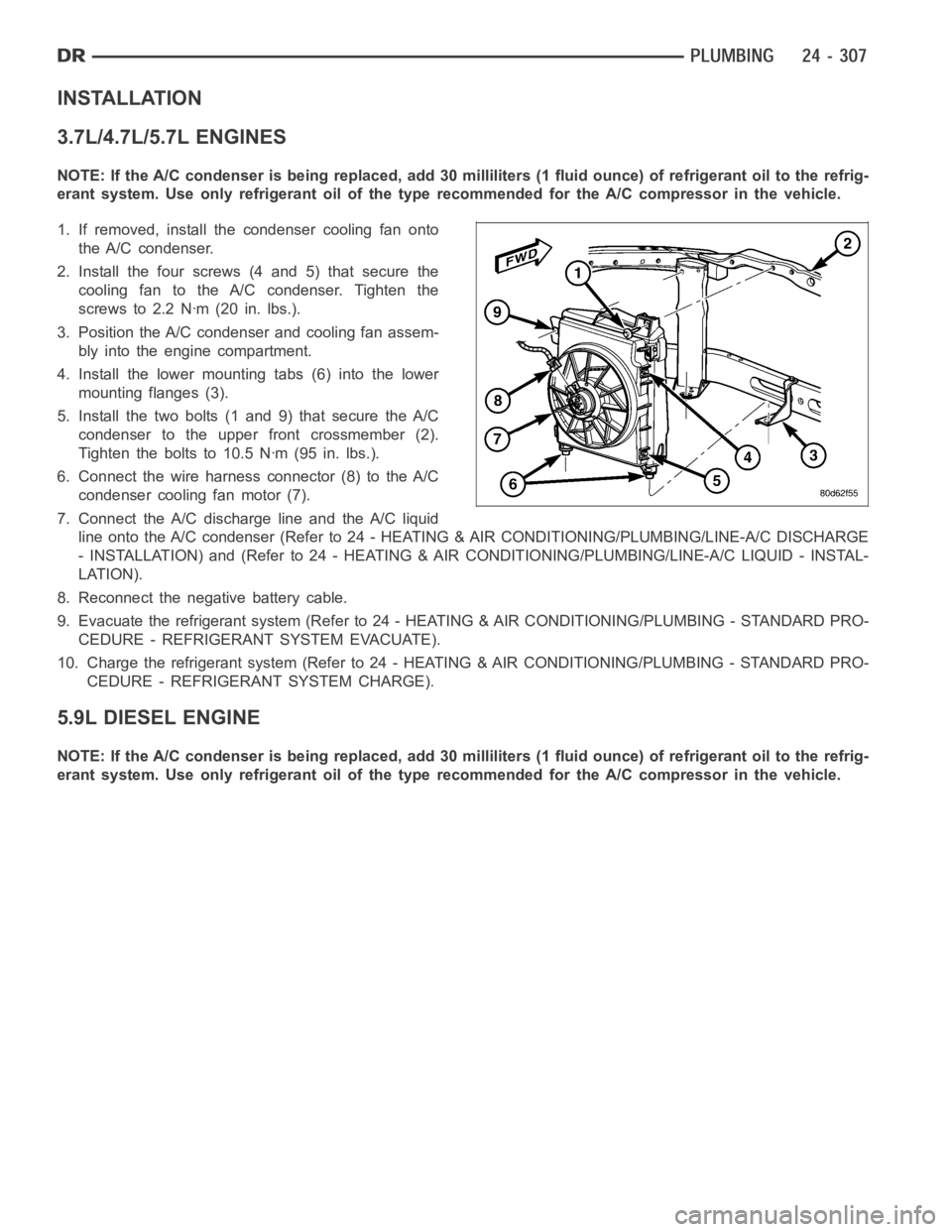
1. If removed, install the condenser cooling fan onto
the A/C condenser.
2. Install the four screws (4 and 5) that secure the
cooling fan to the A/C condenser. Tighten the
screws to 2.2 Nꞏm (20 in. lbs.).
3. Position the A/C condenser and cooling fan assem-
bly into the engine compartment.
4. Install the lower mounting tabs (6) into the lower
mounting flanges (3).
5. Install the two bolts (1 and 9) that secure the A/C
condenser to the upper front crossmember (2).
Tighten the bolts to 10.5 Nꞏm (95 in. lbs.).
6. Connect the wire harness connector (8) to the A/C
condenser cooling fan motor (7).
7. Connect the A/C discharge line and the A/C liquid
line onto the A/C condenser (Refer to 24 - HEATING & AIR CONDITIONING/PLUMBING/LINE-A/C DISCHARGE
- INSTALLATION) and (Refer to 24 - HEATING & AIR CONDITIONING/PLUMBING/LINE-A/C LIQUID - INSTAL-
LATION).
8. Reconnect the negative battery cable.
9. Evacuate the refrigerant system (Refer to 24 - HEATING & AIR CONDITIONING/PLUMBING - STANDARD PRO-
CEDURE - REFRIGERANT SYSTEM EVACUATE).
10. Charge the refrigerant system (Refer to 24 - HEATING & AIR CONDITIONING/PLUMBING - STANDARD PRO-
CEDURE - REFRIGERANT SYSTEM CHARGE).
5.9L DIESEL ENGINE
NOTE: If the A/C condenser is being replaced, add 30 milliliters (1 fluid ounce) of refrigerant oil to the refrig-
erant system. Use only refrigerant oil of the type recommended for the A/C compressor in the vehicle.
Page 5158 of 5267
EVAPORATOR-A/C
DESCRIPTION
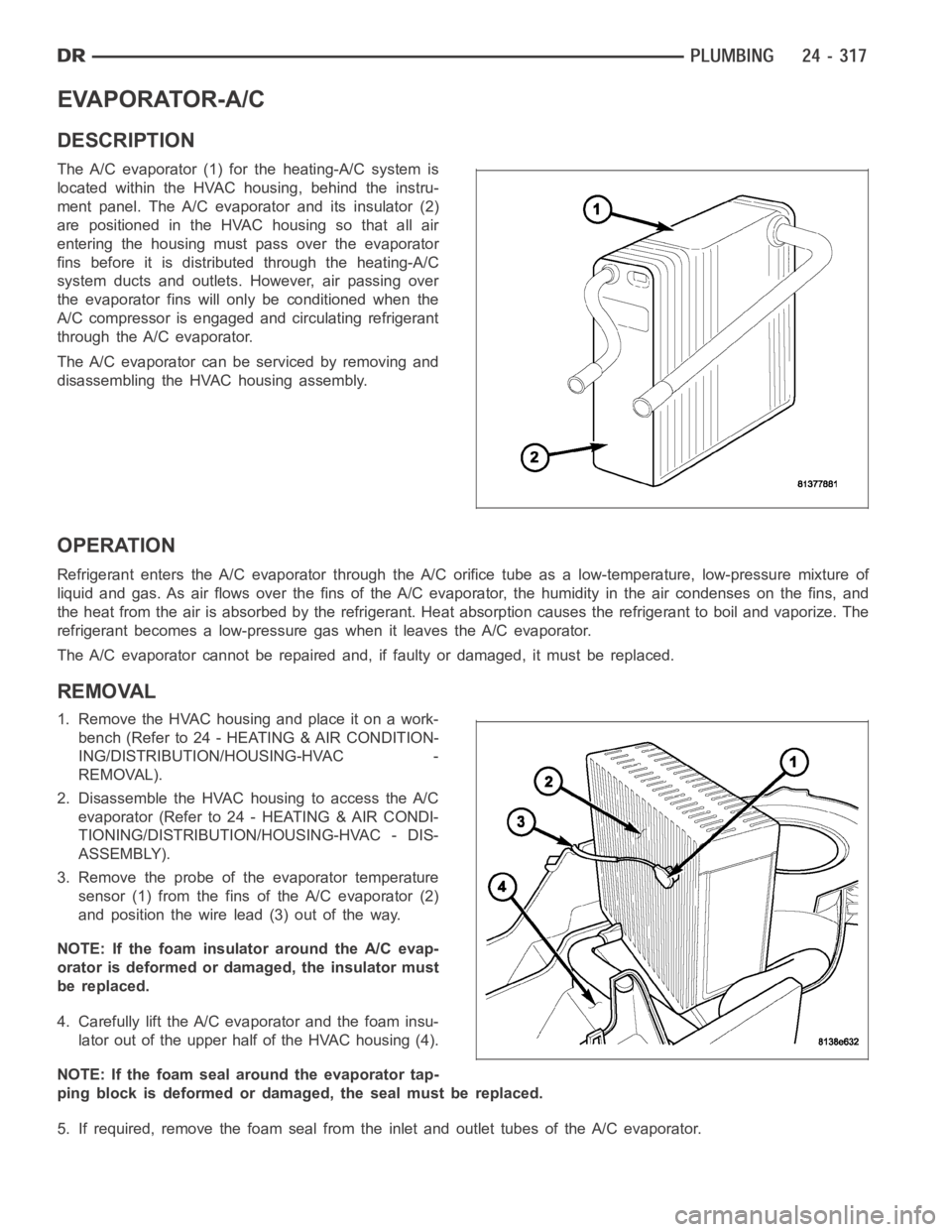
The A/C evaporator (1) for the heating-A/C system is
located within the HVAC housing, behind the instru-
ment panel. The A/C evaporator and its insulator (2)
are positioned in the HVAC housing so that all air
entering the housing must pass over the evaporator
fins before it is distributed through the heating-A/C
system ducts and outlets. However, air passing over
the evaporator fins will only be conditioned when the
A/C compressor is engaged and circulating refrigerant
through the A/C evaporator.
The A/C evaporator can be serviced by removing and
disassembling the HVAC housing assembly.
OPERATION
Refrigerant enters the A/C evaporator through the A/C orifice tube as a low-temperature, low-pressure mixture of
liquid and gas. As air flows over the fins of the A/C evaporator, the humidity in the air condenses on the fins, and
the heat from the air is absorbed by the refrigerant. Heat absorption causes the refrigerant to boil and vaporize. The
refrigerant becomes a low-pressure gas when it leaves the A/C evaporator.
The A/C evaporator cannot be repaired and, if faulty or damaged, it must be replaced.
REMOVAL
1. RemovetheHVAChousingandplaceitonawork-
bench (Refer to 24 - HEATING & AIR CONDITION-
ING/DISTRIBUTION/HOUSING-HVAC -
REMOVAL).
2. Disassemble the HVAC housing to access the A/C
evaporator (Refer to 24 - HEATING & AIR CONDI-
TIONING/DISTRIBUTION/HOUSING-HVAC - DIS-
ASSEMBLY).
3. Remove the probe of the evaporator temperature
sensor (1) from the fins of the A/C evaporator (2)
and position the wire lead (3) out of the way.
NOTE: If the foam insulator around the A/C evap-
orator is deformed or damaged, the insulator must
be replaced.
4. Carefully lift the A/C evaporator and the foam insu-
lator out of the upper half of the HVAC housing (4).
NOTE: If the foam seal around the evaporator tap-
ping block is deformed or damaged, the seal must be replaced.
5. If required, remove the foam seal from the inlet and outlet tubes of the A/Cevaporator.
Page 5161 of 5267
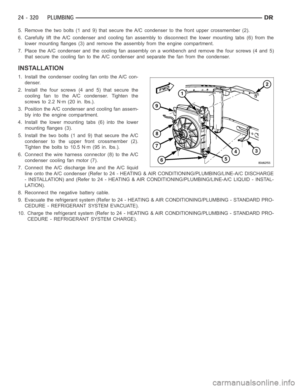
5. Remove the two bolts (1 and 9) that secure the A/C condenser to the front upper crossmember (2).
6. Carefully lift the A/C condenser and cooling fan assembly to disconnectthe lower mounting tabs (6) from the
lower mounting flanges (3) and remove the assembly from the engine compartment.
7. Place the A/C condenser and the cooling fan assembly on a workbench and remove the four screws (4 and 5)
that secure the cooling fan to the A/C condenser and separate the fan from the condenser.
INSTALLATION
1. Install the condenser cooling fan onto the A/C con-
denser.
2. Install the four screws (4 and 5) that secure the
cooling fan to the A/C condenser. Tighten the
screws to 2.2 Nꞏm (20 in. lbs.).
3. Position the A/C condenser and cooling fan assem-
bly into the engine compartment.
4. Install the lower mounting tabs (6) into the lower
mounting flanges (3).
5. Install the two bolts (1 and 9) that secure the A/C
condenser to the upper front crossmember (2).
Tighten the bolts to 10.5 Nꞏm (95 in. lbs.).
6. Connect the wire harness connector (8) to the A/C
condenser cooling fan motor (7).
7. Connect the A/C discharge line and the A/C liquid
line onto the A/C condenser (Refer to 24 - HEATING & AIR CONDITIONING/PLUMBING/LINE-A/C DISCHARGE
- INSTALLATION) and (Refer to 24 - HEATING & AIR CONDITIONING/PLUMBING/LINE-A/C LIQUID - INSTAL-
LATION).
8. Reconnect the negative battery cable.
9. Evacuate the refrigerant system (Refer to 24 - HEATING & AIR CONDITIONING/PLUMBING - STANDARD PRO-
CEDURE - REFRIGERANT SYSTEM EVACUATE).
10. Charge the refrigerant system (Refer to 24 - HEATING & AIR CONDITIONING/PLUMBING - STANDARD PRO-
CEDURE - REFRIGERANT SYSTEM CHARGE).
Page 5188 of 5267
OIL-A/C REFRIGERANT
DESCRIPTION
The refrigerant oil used in R-134a refrigerant systems is a synthetic-based, polyalkylene glycol (PAG), wax-free
lubricant. Mineral-based R-12 refrigerant oils are not compatible with PAG oils, and should never be introduced to
an R-134a refrigerant system.
There are different PAG oils available, and each contains a different additive package. Useonlyrefrigerant oil of the
same type as recommended to service the refrigerant system (always refer to the specification tagincluded with
the replacement A/C compressor or the A/C Underhood Specification Label located in the engine compartment).
The Denso 10S17 A/C compressor used in this vehicle when equipped with the 3.7L, 4.7L, 5.7L or 8.3L engine is
designed to use ND-8 PAG refrigerant oil. Use only this type of refrigerantoil when servicing the A/C compressor for
these engines.
The Visteon HS-18 A/C compressor used in this vehicle when equipped with 5.9L diesel engine is designed to use
VC-46 PAG refrigerant oil. Use only this type of refrigerant oil when servicing this A/C compressor.
OPERATION
After performing any refrigerant recovery or recycling operation, always replenish the refrigerant system with the
same amount of the recommended refrigerant oil as was removed. Too little refrigerant oil can cause A/C compres-
sor damage, and too much can reduce A/C system performance.
PAG refrigerant oil is more hygroscopic than mineral oil, and will absorb any moisture it comes into contact with,
even moisture in the air. The PAG oil container should always be kept tightly capped until it is ready to be used.
After use, recap the oil container immediately to prevent moisture contamination.
STANDARD PROCEDURE
REFRIGERANT OIL LEVEL
When an A/C system is assembled at the factory, all components except the A/C compressor are refrigerant oil free.
After the refrigerant system has been charged and operated, the refrigerant oil in the A/C compressor is dispersed
throughout the refrigerant system. The accumulator, A/C evaporator, A/Ccondenser and the A/C compressor will
each retain a significant amount of the needed refrigerant oil.
It is important to have the correct amount of refrigerant oil in the A/C system. This ensures proper lubrication of the
A/C compressor. Too little oil will result in damage to the A/C compressor,while too much oil will reduce the cooling
capacity of the A/C system and consequently result in higher discharge airtemperatures.
CAUTION: The refrigerant oil in the R-134a A/C system is unique depending on the A/C compressor used.
Use only PAG oils that are designed to work with R-134a refrigerant and the A/C compressor in the vehicle.
Always refer to the A/C Underhood Specification Label for the correct oil designation. The oil container
should be kept tightly capped until it is ready for use and then tightly capped after use to prevent contam-
ination from dirt and moisture. Refrigerant oil will quickly absorb any moisture it comes in contact with,
therefore, special effort must be used to keep all R-134a system components moisture-free. Moisture in the
refrigerant oil is very difficult toremove and will cause a reliability problem with the A/C compressor.
NOTE: Most reclaim/recycling equipment will measure the lubricant beingremoved during recovery. This
amount of lubricant should be added back into the system. Refer to the reclaim/recycling equipment man-
ufacturers instructions.
It will not be necessary to check the oil level in the A/C compressor or to addoil, unless there has been an oil loss.
An oil loss may occur due to a rupture or leak from a refrigerant line, a connector fitting, a component, or a com-
ponent seal. If a leak occurs, add 30 milliliters (1 fluid ounce) of refrigerant oil to the refrigerant system after the
repair has been made. Refrigerant oil loss will be evident at the leak pointby the presence of a wet, shiny surface
around the leak.
Refrigerant oil must be added when an accumulator, A/C evaporator or A/C condenser is replaced. See the Refrig-
erant Oil Capacities chart. When an A/C compressor is replaced, the refrigerant oil must be drained from the old
Page 5196 of 5267
CATALYST MONITOR
To comply with clean air regulations, vehicles are equipped with catalytic converters. These converters reduce the
emission of hydrocarbons, oxides of nitrogen and carbon monoxide.
Normal vehicle miles or engine misfire can cause a catalyst to decay. This can increase vehicle emissions and
deteriorate engine performance, driveability and fuel economy.
The catalyst monitor uses dual oxygen sensors (O2S’s) to monitor the efficiency of the converter. The dual O2S’s
sensor strategy is based on the fact that as a catalyst deteriorates, its oxygen storage capacity and its efficiency are
both reduced. By monitoring the oxygen storage capacity of a catalyst, itsefficiency can be indirectly calculated. The
upstream O2S is used to detect the amount of oxygen in the exhaust gas beforethe gas enters the catalytic con-
verter. The PCM calculates the A/F mixture from the output of the O2S. A low voltage indicates high oxygen content
(lean mixture). A high voltage indicates a low content of oxygen (rich mixture).
When the upstream O2S detects a lean condition, there is an abundance of oxygen in the exhaust gas. A function-
ing converter would store this oxygen so it can use it for the oxidation of HCand CO. As the converter absorbs the
oxygen, there will be a lack of oxygen downstream of the converter. The output of the downstream O2S will indicate
limited activity in this condition.
As the converter loses the ability to store oxygen, the condition can be detected from the behavior of the down-
stream O2S. When the efficiency drops, no chemical reaction takes place. This means the concentration of oxygen
will be the same downstream as upstream. The output voltage of the downstream O2S copies the voltage of the
upstream sensor. The only difference is a time lag (seen by the PCM) betweenthe switching of the O2S’s.
To monitor the system, the number of lean-to-rich switches of upstream anddownstream O2S’s is counted. The
ratio of downstream switches to upstream switches is used to determine whether the catalyst is operating properly.
An effective catalyst will have fewer downstream switches than it has upstream switches i.e., a ratio closer to zero.
For a totally ineffective catalyst, this ratio will be one-to-one, indicating that no oxidation occurs in the device.
The system must be monitored so that when catalyst efficiency deteriorates and exhaust emissions increase to over
the legal limit, the MIL will be illuminated.
TRIP DEFINITION
The term “Trip” has different meanings depending on what the circumstances are. If the MIL (Malfunction Indicator
Lamp) is OFF, a Trip is defined as when the Oxygen Sensor Monitor and the Catalyst Monitor have been completed
in the same drive cycle.
When any Emission DTC is set, the MIL on the dash is turned ON. When the MIL is ON, it takes 3 good trips to turn
the MIL OFF. In this case, it depends on what type of DTC is set to know what a “Trip” is.
For the Fuel Monitor or Mis-Fire Monitor (continuous monitor), the vehicle must be operated in the “Similar Condition
Window” for a specified amount of time to be considered a Good Trip.
If a Non-Continuous OBDII Monitor fails twice in a row and turns ON the MIL, re-running that monitor which previ-
ously failed, on the next start-up and passing the monitor, is considered tobeaGoodTrip.Thesewillincludethe
following:
Oxygen Sensor
Catalyst Monitor
Purge Flow Monitor
Leak Detection Pump Monitor (if equipped)
EGR Monitor (if equipped)
Oxygen Sensor Heater Monitor
If any other Emission DTC is set (not an OBDII Monitor), a Good Trip is considered to be when the Oxygen Sensor
Monitor and Catalyst Monitor have been completed; or 2 Minutes of engine run time if the Oxygen Sensor Monitor
or Catalyst Monitor have been stopped from running.
It can take up to 2 Failures in a row to turn on the MIL. After the MIL is ON, it takes3GoodTripstoturntheMIL
OFF. After the MIL is OFF, the PCM will self-erase the DTC after 40 Warm-up cycles. A Warm-up cycle is counted
when the ECT (Engine Coolant Temperature Sensor) has crossed 160°F (71.1C) and has risen by at least 40°F
(4.4°C) since the engine has been started.
Page 5200 of 5267
If the MIL is ON and a DTC was set by the Fuel Monitor or Misfire Monitor (both continuous monitors), the
vehicle must be operated in the Similar Condition Window for a specified amount of time.
If the MIL is ON and a DTC was set by a Task Manager commanded once-per-trip monitor (such as the Oxy-
gen Sensor Monitor, Catalyst Monitor, Purge Flow Monitor, Leak DetectionPump Monitor, EGR Monitor or
Oxygen Sensor Heater Monitor), a good trip is when the monitor is passed on the next start-up.
If the MIL is ON and any other emissions DTC was set (not an OBD II monitor), a good trip occurs when the
Oxygen Sensor Monitor and Catalyst Monitor have been completed, or two minutes of engine run time if the
Oxygen Sensor Monitor and Catalyst Monitor have been stopped from running.
Fuel System Good Trip
To count a good trip (three required) and turn off the MIL, the following conditions must occur:
Engine in closed loop
Operating in Similar Conditions Window
Short Term multiplied by Long Term less than threshold
Less than threshold for a predetermined time
If all of the previous criteria are met, the PCM will count a good trip (threerequired) and turn off the MIL.
Misfire Good Trip
If the following conditions are met the PCM will count one good trip (three required) in order to turn off the MIL:
Operating in Similar Condition Window
1000 engine revolutions with no misfire
Warm-Up Cycles
Once the MIL has been extinguished by the Good Trip Counter, the PCM automatically switches to a Warm-Up
CycleCounterthatcanbeviewedontheDRBIII.Warm-UpCyclesareusedtoerase DTCs and Freeze Frames.
Forty Warm-Up cycles must occur in order for the PCM to self-erase a DTC and Freeze Frame. A Warm-Up Cycle
is defined as follows:
Engine coolant temperature must start below and rise above 160° F (71.1°C).
Engine coolant temperature must rise by 40° F (4.4°C)
No further faults occur
Freeze Frame Data Storage
Once a failure occurs, the Task Manager records several engine operating conditions and stores it in a Freeze
Frame. The Freeze Frame is considered one frame of information taken by an on-board data recorder. When a fault
occurs, the PCM stores the input data from various sensors so that technicians can determine under what vehicle
operating conditions the failure occurred.
The data stored in Freeze Frame is usually recorded when a system fails the first time for two trip faults. Freeze
Frame data will only be overwritten by a different fault with a higher priority.
CAUTION: Erasing DTCs, either with the DRB III or by disconnecting the battery, also clears all Freeze
Frame data.
Similar Conditions Window
The Similar Conditions Window displays information about engine operation during a monitor. Absolute MAP (engine
load) and Engine RPM are stored in this window when a failure occurs. There are two different Similar conditions
Windows: Fuel System and Misfire.
FUEL SYSTEM
Fuel System Similar Conditions Window— An indicator that ’Absolute MAP When Fuel Sys Fail’ and ’RPM
When Fuel Sys Failed’ are all in the same range when the failure occurred. Indicated by switching from ’NO’
to ’YES’.
Absolute MAP When Fuel Sys Fail— The stored MAP reading at the time of failure. Informs the user at
what engine load the failure occurred.
Absolute MAP— A live reading of engine load to aid the user in accessing the Similar Conditions Window.
RPM When Fuel Sys Fail— The stored RPM reading at the time of failure. Informs the user at what engine
RPM the failure occurred.
Page 5201 of 5267
Engine RPM— A live reading of engine RPM to aid the user in accessing the Similar Conditions Window.
Adaptive Memory Factor— The PCM utilizes both Short Term Compensation and Long Term Adaptive to
calculate the Adaptive Memory Factor for total fuel correction.
Upstream O2S Volts— A live reading of the Oxygen Sensor to indicate its performance. For example, stuck
lean, stuck rich, etc.
SCW Time in Window (Similar Conditions Window Time in Window)—Atimer used by the PCM that
indicates that, after all Similar Conditions have been met, if there has been enough good engine running time
in the SCW without failure detected. This timer is used to increment a Good Trip.
Fuel System Good Trip Counter—ATripCounterusedtoturnOFFtheMILforFuelSystemDTCs.To
increment a Fuel System Good Trip, the engine must be in the Similar Conditions Window, Adaptive Memory
Factor must be less than calibrated threshold and the Adaptive Memory Factor must stay below that threshold
for a calibrated amount of time.
Test Done This Trip— Indicates that the monitor has already been run and completed during the current trip.
MISFIRE
Same Misfire Warm-Up State— Indicates if the misfire occurred when the engine was warmed up above
160° F (71.1°C).
In Similar Misfire Window— An indicator that ’Absolute MAP When Misfire Occurred’ and ’RPM When Mis-
fire Occurred’ are all in the same range when the failure occurred. Indicated by switching from ’NO’ to ’YES’.
Absolute MAP When Misfire Occurred— The stored MAP reading at the time of failure. Informs the user at
what engine load the failure occurred.
Absolute MAP— A live reading of engine load to aid the user in accessing the Similar Conditions Window.
RPM When Misfire Occurred— The stored RPM reading at the time of failure. Informs the user at what
engine RPM the failure occurred.
Engine RPM— A live reading of engine RPM to aid the user in accessing the Similar Conditions Window.
Adaptive Memory Factor— The PCM utilizes both Short Term Compensation and Long Term Adaptive to
calculate the Adaptive Memory Factor for total fuel correction.
200 Rev Counter— Counts 0–100 720 degree cycles.
SCW Cat 200 Rev Counter— Counts when in similar conditions.
SCW FTP 1000 Rev Counter— Counts 0–4 when in similar conditions.
Misfire Good Trip Counter— Counts up to three to turn OFF the MIL.
Misfire Data— Data collected during test.
Test Done This Trip— Indicates YES when the test is done.
NON-MONITORED CIRCUITS
The PCM does not monitor the following circuits, systems and conditions that could have malfunctions causing
driveability problems. The PCM might not store diagnostic trouble codes for these conditions. However, problems
with these systems may cause the PCM to store diagnostic trouble codes for other systems or components.EXAM-
PLE:a fuel pressure problem will not register a fault directly, but could causea rich/lean condition or misfire. This
could cause the PCM to store an oxygen sensor or misfire diagnostic troublecode
FUEL PRESSURE
The fuel pressure regulator controls fuel system pressure. The PCM cannotdetect a clogged fuel pump inlet filter,
clogged in-line fuel filter, or a pinched fuel supply or return line. However, these could result in a rich or lean con-
dition causing the PCM to store an oxygen sensor or fuel system diagnostic trouble code.
SECONDARY IGNITION CIRCUIT
The PCM cannot detect an inoperative ignition coil, fouled or worn spark plugs, ignition cross firing, or open spark
plug cables.
CYLINDER COMPRESSION
The PCM cannot detect uneven, low, or high engine cylinder compression.
Page 5212 of 5267
ORVR
DESCRIPTION
The ORVR (On-Board Refueling Vapor Recovery) system consists of a unique fuel tank, flow management valve,
fluid control valve, one-way check valve and vapor canister.
OPERATION
The ORVR (On-Board Refueling Vapor Recovery) system is used to remove excess fuel tank vapors. This is done
while the vehicle is being refueled.
Fuel flowing into the fuel filler tube (approx. 1” I.D.) creates an aspiration effect drawing air into the fuel fill tube.
During refueling, the fuel tank is vented to the EVAP canister to capture escaping vapors. With air flowing into the
filler tube, there are no fuel vapors escaping to the atmosphere. Once the refueling vapors are captured by the
EVAP canister, the vehicle’s computer controlled purge system draws vapor out of the canister for the engine to
burn. The vapor flow is metered by the purge solenoid so that there is no, or minimal impact on driveability or
tailpipe emissions.
As fuel starts to flow through the fuel fill tube, it opens the normally closed check valve and enters the fuel tank.
Vapor or air is expelled from the tank through the control valve and on to thevapor canister. Vapor is absorbed in
the EVAP canister until vapor flow in the lines stops. This stoppage occursfollowing fuel shut-off, or by having the
fuel level in the tank rise high enough to close the control valve. This control valve contains a float that rises to seal
the large diameter vent path to the EVAP canister. At this point in the refueling process, fuel tank pressure
increases, the check valve closes (preventing liquid fuel from spiting back at the operator), and fuel then rises up
the fuel filler tube to shut off the dispensing nozzle.