2006 DODGE RAM SRT-10 ABS
[x] Cancel search: ABSPage 5112 of 5267
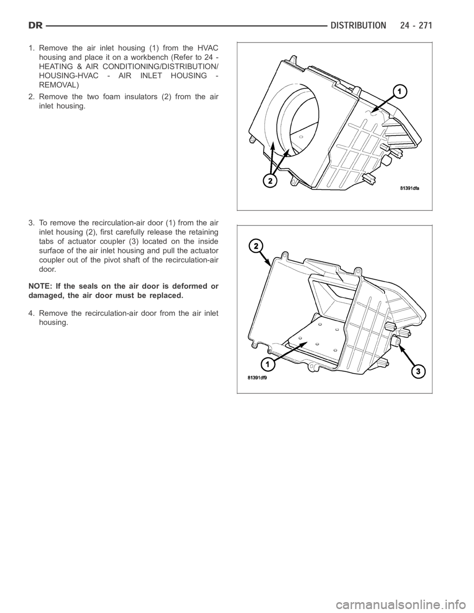
1. Remove the air inlet housing (1) from the HVAC
housing and place it on a workbench (Refer to 24 -
HEATING & AIR CONDITIONING/DISTRIBUTION/
HOUSING-HVAC - AIR INLET HOUSING -
REMOVAL)
2. Remove the two foam insulators (2) from the air
inlet housing.
3. To remove the recirculation-air door (1) from the air
inlet housing (2), first carefully release the retaining
tabs of actuator coupler (3) located on the inside
surface of the air inlet housing and pull the actuator
coupler out of the pivot shaft of the recirculation-air
door.
NOTE: If the seals on the air door is deformed or
damaged, the air door must be replaced.
4. Remove the recirculation-air door from the air inlet
housing.
Page 5113 of 5267
ASSEMBLY
HVAC HOUSING
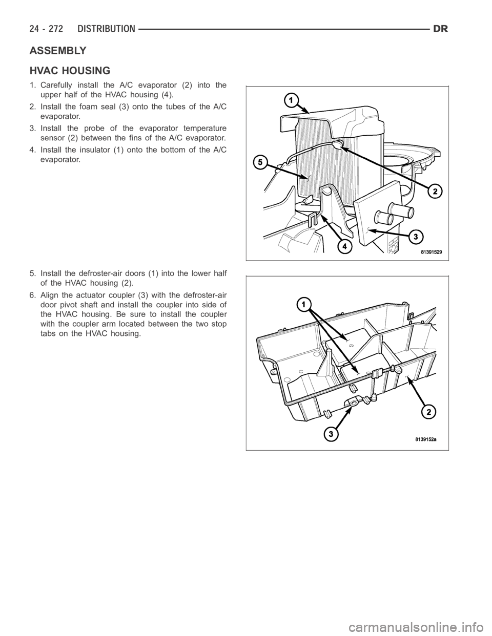
1. Carefully install the A/C evaporator (2) into the
upper half of the HVAC housing (4).
2. Install the foam seal (3) onto the tubes of the A/C
evaporator.
3. Install the probe of the evaporator temperature
sensor (2) between the fins of the A/C evaporator.
4. Install the insulator (1) onto the bottom of the A/C
evaporator.
5. Install the defroster-air doors (1) into the lower half
of the HVAC housing (2).
6. Align the actuator coupler (3) with the defroster-air
door pivot shaft and install the coupler into side of
the HVAC housing. Be sure to install the coupler
with the coupler arm located between the two stop
tabs on the HVAC housing.
Page 5114 of 5267
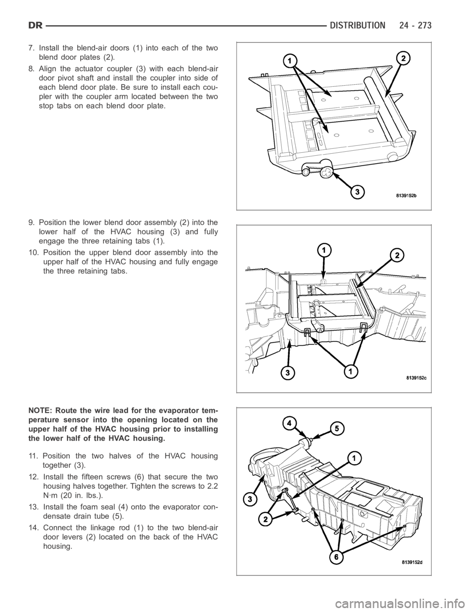
7. Install the blend-air doors (1) into each of the two
blend door plates (2).
8. Align the actuator coupler (3) with each blend-air
door pivot shaft and install the coupler into side of
each blend door plate. Be sure to install each cou-
pler with the coupler arm located between the two
stop tabs on each blend door plate.
9. Position the lower blend door assembly (2) into the
lower half of the HVAC housing (3) and fully
engage the three retaining tabs (1).
10. Position the upper blend door assembly into the
upper half of the HVAC housing and fully engage
the three retaining tabs.
NOTE: Route the wire lead for the evaporator tem-
perature sensor into the opening located on the
upper half of the HVAC housing prior to installing
the lower half of the HVAC housing.
11. Position the two halves of the HVAC housing
together (3).
12. Install the fifteen screws (6) that secure the two
housing halves together. Tighten the screws to 2.2
Nꞏm (20 in. lbs.).
13. Install the foam seal (4) onto the evaporator con-
densate drain tube (5).
14. Connect the linkage rod (1) to the two blend-air
door levers (2) located on the back of the HVAC
housing.
Page 5116 of 5267
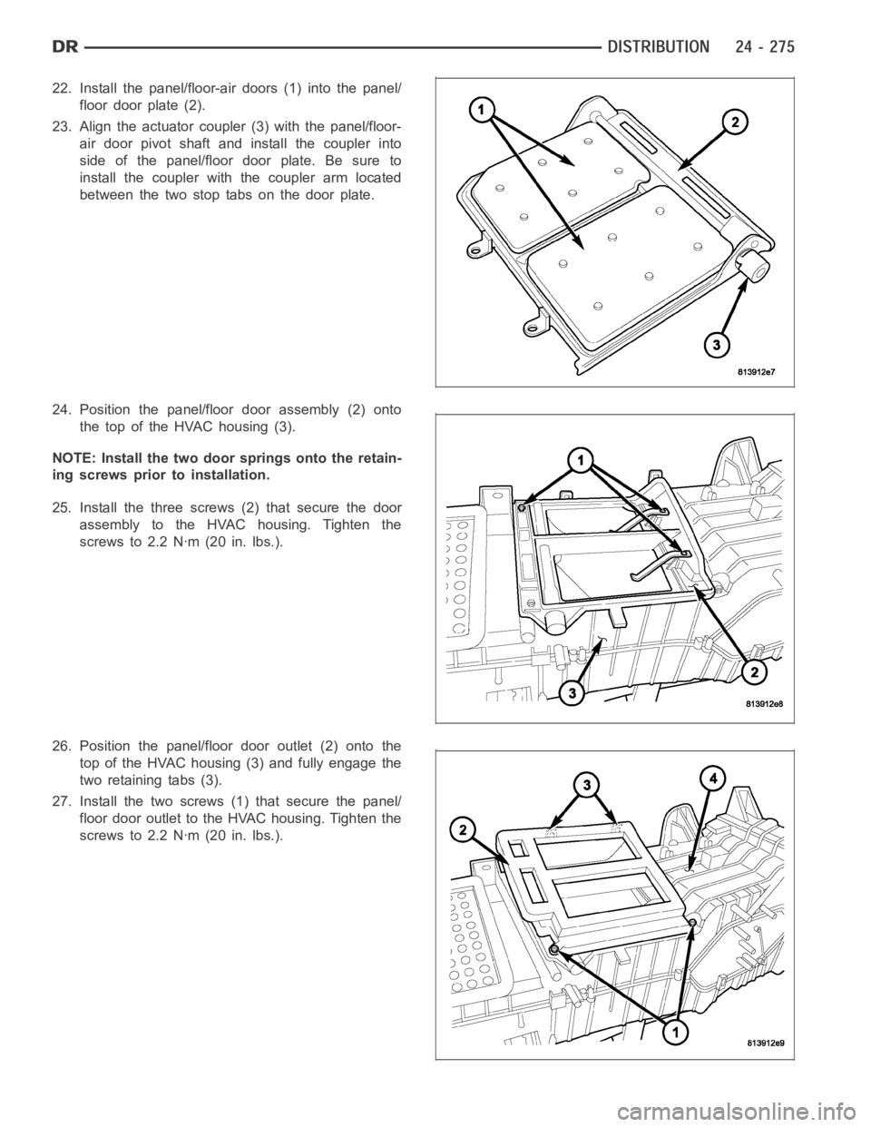
22. Install the panel/floor-air doors (1) into the panel/
floor door plate (2).
23. Align the actuator coupler (3) with the panel/floor-
air door pivot shaft and install the coupler into
side of the panel/floor door plate. Be sure to
install the coupler with the coupler arm located
between the two stop tabs on the door plate.
24. Position the panel/floor door assembly (2) onto
the top of the HVAC housing (3).
NOTE: Install the two door springs onto the retain-
ing screws prior to installation.
25. Install the three screws (2) that secure the door
assembly to the HVAC housing. Tighten the
screws to 2.2 Nꞏm (20 in. lbs.).
26. Position the panel/floor door outlet (2) onto the
top of the HVAC housing (3) and fully engage the
two retaining tabs (3).
27. Install the two screws (1) that secure the panel/
floor door outlet to the HVAC housing. Tighten the
screws to 2.2 Nꞏm (20 in. lbs.).
Page 5118 of 5267

AIR INLET HOUSING
NOTE: The air inlet housing must be removed from HVAC housing and disassembled for service of the
recirculation-air door.
NOTE: If the seals on the air door is deformed or
damaged, the air door must be replaced.
1. Position the recirculation-air door (1) into the air
inlet housing (2).
CAUTION: Make sure that the recirculation-air
door pivot shaft is properly seated in the pivot
seat located in the air inlet housing.
2. Align the actuator coupler (3) with the recirculation-
air door pivot shaft and install the coupler until the
coupler retaining tabs are fully engaged to the air
inlet housing. Be sure to install the coupler with the
coupler arm located between the two stop tabs on
the air inlet housing.
3. Install the two foam insulators (2) into the air inlet
housing (1).
4. Install the air inlet housing onto the HVAC housing
(Refer to 24 - HEATING & AIR CONDITIONING/
DISTRIBUTION/HOUSING-HVAC - AIR INLET
HOUSING - INSTALLATION).
INSTALLATION
HVAC HOUSING ASSEMBLY
NOTE: The HVAC housing must be removedfrom the vehicle and disassembled for service of the A/C evap-
orator, evaporator temperature sensor, mode-air and blend-air doors.
Page 5128 of 5267
WARNING: The engine cooling system is designed to develop internal pressures up to 145 kilopascals (21
pounds per square inch). Do not remove or loosen the coolant pressure cap, cylinder block drain plugs,
radiator drain, radiator hoses, heater hoses, or hose clamps while the engine cooling system is hot and
under pressure. Allow the vehicle to cool for a minimum of 15 minutes beforeopening the cooling system
for service. Failure to observe this warning can result in serious burns from the heated engine coolant.
CAUTION
CAUTION: Never add R-12 to a refrigerant system designed to use R-134a. Do not use R-12 equipment or
parts on an R-134a A/C system. These refrigerants are not compatible and damage to the A/C system will
result.
CAUTION: Never use R-12 refrigerant oil in a A/C system designed to use R-134a refrigerant oil. These
refrigerant oils are not compatible and damage to the A/C system will result.
CAUTION: The use of A/C system sealers may result in damage to A/C refrigerant recovery/evacuation/re-
charging equipment and/or A/C system. Many federal, state/provincial and local regulations prohibit the
recharge of A/C systems with known leaks. DaimlerChrysler recommends thedetection of A/C system leaks
through the use of approved leak detectors and fluorescent leak detectiondyes. Vehicles found with A/C
system sealers should be treated as contaminated and replacement of the entire A/C refrigerant system is
recommended. A/C systems found to be contaminated with A/C system sealers, A/C stop-leak products or
seal conditioners voids the warranty for the A/C system.
CAUTION: Recover the refrigerant before opening any fitting or connection. Open the fittings with caution,
even after the system has been discharged. Never open or loosen a connection before recovering the refrig-
erant.
CAUTION: If equipped, do not remove the secondary retention clip from any spring-lock coupler connection
while the refrigerant system is under pressure. Recover the refrigerant before removing the secondary
retention clip. Open the fittings with caution, even after the system has been discharged. Never open or
loosen a connection before recovering the refrigerant.
CAUTION: The internal parts of the A/C system will remain stable as long as moisture-free refrigerant and
refrigerant oil is used. Abnormal amounts of dirt, moisture or air can upset the chemical stability. This may
cause operational troubles or even serious damage if present in more than very small quantities. Before
disconnecting a component, clean the outside of the fittings thoroughly to prevent contamination from
entering the refrigerant system. Keep service tools and the work area clean. Do not open the refrigerant
system or uncap a replacement component until you are ready to service the system. Immediately after
disconnecting a component from the refrigerant system, seal the open fittings with a cap or plug. This will
prevent contamination from entering the A/C system.
CAUTION: Refrigerant oil will absorb moisture from the atmosphere if leftuncapped. Do not open a con-
tainer of refrigerant oil until you are ready to use it. Replace the cap on the oil container immediately after
using. Store refrigerant oil only in a clean, airtight, and moisture-freecontainer.
CAUTION: Do not overcharge the refrigerant system. Overcharging will cause excessive compressor head
pressure and can cause compressor noise and A/C system failure.
Page 5133 of 5267
ACCUMULATOR-A/C
DESCRIPTION
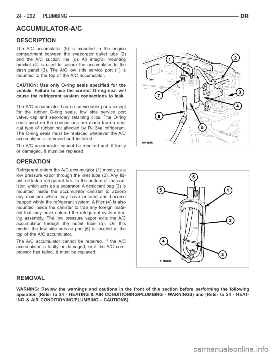
The A/C accumulator (5) is mounted in the engine
compartment between the evaporator outlet tube (2)
and the A/C suction line (6). An integral mounting
bracket (4) is used to secure the accumulator to the
dash panel (3). The A/C low side service port (1) is
mountedtothetopoftheA/Caccumulator.
CAUTION: Use only O-ring seals specified for the
vehicle. Failure to use the correct O-ring seal will
cause the refrigerant system connections to leak.
The A/C accumulator has no serviceable parts except
for the rubber O-ring seals, low side service port
valve, cap and secondary retaining clips. The O-ring
seals used on the connections are made from a spe-
cial type of rubber not affected by R-134a refrigerant.
The O-ring seals must be replaced whenever the A/C
accumulator is removed and installed.
The A/C accumulator cannot be repaired and, if faulty
or damaged, it must be replaced.
OPERATION
Refrigerant enters the A/C accumulator (1) mostly as a
low pressure vapor through the inlet tube (2). Any liq-
uid, oil-laden refrigerant falls to the bottom of the can-
ister, which acts as a separator. A desiccant bag (3) is
mounted inside the accumulator canister to absorb
any moisture which may have entered and become
trapped within the refrigerant system. A filter (4) is also
mounted inside the canister to trap any foreign mate-
rial that may have entered the refrigerant system dur-
ing assembly. The low pressure vapor exits the A/C
accumulator through the outlet tube (5). On this
model, the low side service port (6) is located at the
top of the A/C accumulator.
The A/C accumulator cannot be repaired. If the A/C
accumulator is faulty or damaged, or if the A/C com-
pressor has failed, it must be replaced.
REMOVAL
WARNING: Review the warnings and cautions in the front of this section before performing the following
operation (Refer to 24 - HEATING & AIR CONDITIONING/PLUMBING - WARNINGS) and (Refer to 24 - HEAT-
ING & AIR CONDITIONING/PLUMBING - CAUTIONS).
Page 5146 of 5267
CONDENSER-A/C
DESCRIPTION
The A/C condenser is located in the front of the engine compartment behind the grille. The A/C condenser is a heat
exchanger that allows the high-pressure refrigerant gas being dischargedbytheA/Ccompressortogiveupitsheat
to the air passing over the condenser fins, which causes the refrigerant tocool and change to a liquid state.
OPERATION
When air passes through the fins of the A/C condenser, the high-pressure refrigerant gas within the A/C condenser
gives up its heat. The refrigerant then condenses as it leaves the A/C condenser and becomes a high-pressure
liquid. The volume of air flowing over the condenser fins is critical to theproper cooling performance of the A/C
system. Therefore, it is important that there are no objects placed in front of the radiator grille openings at the front
of the vehicle or foreign material on the condenser fins that might obstruct proper air flow. Also, any factory-installed
air seals or shrouds must be properly reinstalled following radiator or A/C condenser service.
The A/C condenser cannot be repaired and, if faulty or damaged, it must be replaced.
REMOVAL
3.7L/4.7L/5.7L ENGINES
WARNING: Refer to the applicable warnings and cautions for this system before performing the following
operation (Refer to 24 - HEATING & AIR CONDITIONING/PLUMBING - WARNINGS) and (Refer to 24 - HEAT-
ING & AIR CONDITIONING/PLUMBING - CAUTIONS). Failure to follow the warnings and cautions could result
in possible personal injury or death.
1. Recover the refrigerant from the refrigerant system
(Refer to 24 - HEATING & AIR CONDITIONING/
PLUMBING - STANDARD PROCEDURE -
REFRIGERANT SYSTEM RECOVERY).
2. Disconnect and isolate the negative battery cable.
3. Disconnect the A/C discharge line and the A/C liq-
uidlinefromtheA/Ccondenser(Referto24-
HEATING & AIR CONDITIONING/PLUMBING/
LINE-A/C DISCHARGE - REMOVAL) and (Refer to
24 - HEATING & AIR CONDITIONING/PLUMBING/
LINE-A/C LIQUID - REMOVAL).
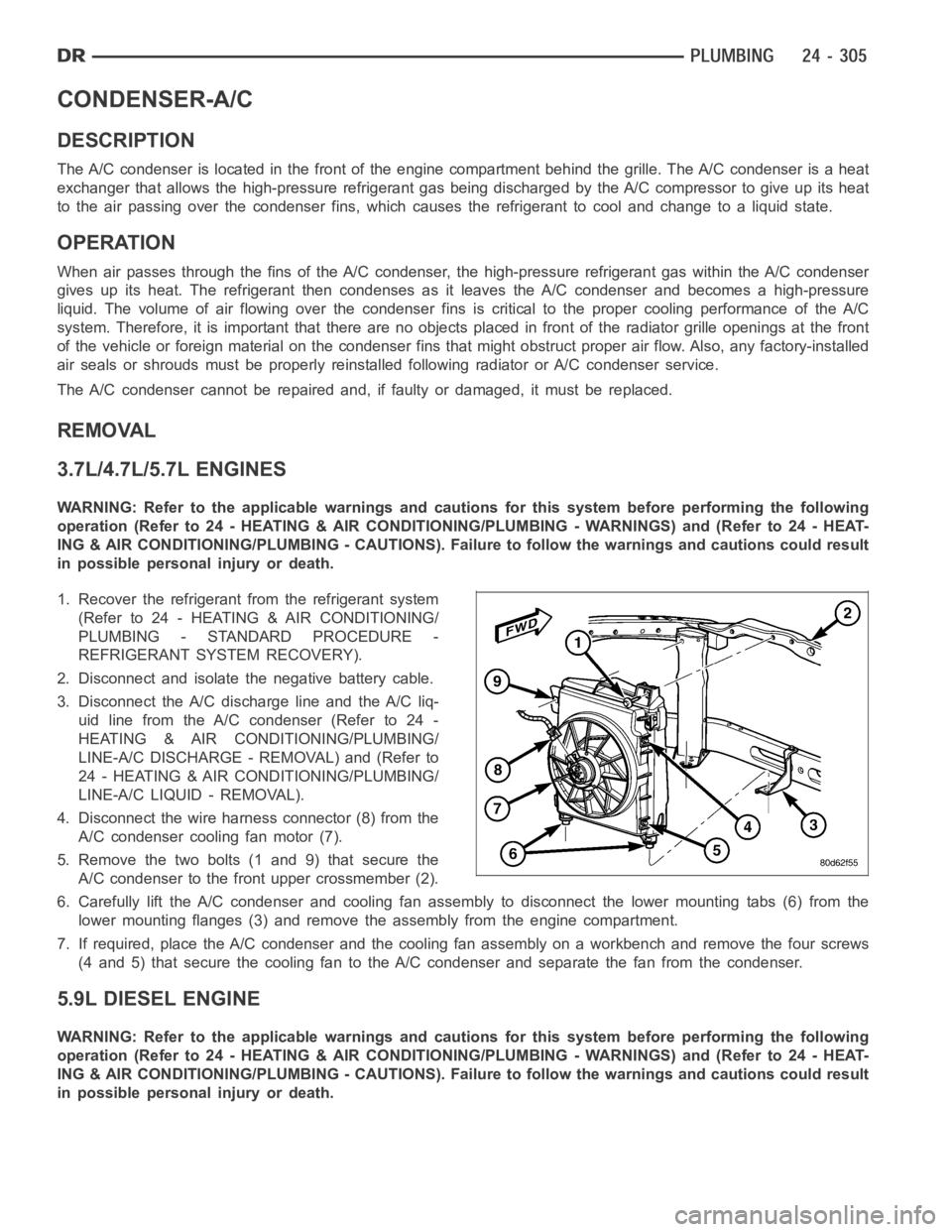
4. Disconnect the wire harness connector (8) from the
A/C condenser cooling fan motor (7).
5. Remove the two bolts (1 and 9) that secure the
A/C condenser to the front upper crossmember (2).
6. Carefully lift the A/C condenser and cooling fan assembly to disconnectthe lower mounting tabs (6) from the
lower mounting flanges (3) and remove the assembly from the engine compartment.
7. If required, place the A/C condenser and the cooling fan assembly on a workbench and remove the four screws
(4 and 5) that secure the cooling fan to the A/C condenser and separate the fan from the condenser.
5.9L DIESEL ENGINE
WARNING: Refer to the applicable warnings and cautions for this system before performing the following
operation (Refer to 24 - HEATING & AIR CONDITIONING/PLUMBING - WARNINGS) and (Refer to 24 - HEAT-
ING & AIR CONDITIONING/PLUMBING - CAUTIONS). Failure to follow the warnings and cautions could result
in possible personal injury or death.