Page 4289 of 5267
18. Install the rear output shaft bearing into the rear
case (1) using Seal Installer 8152 (3) and Univer-
sal Handle C-4171 (2).
19. Install the rear output shaft bearing snap-ring into
the rear case half.
INPUT AND PLANETARY GEAR
1. Lubricate gears and thrust washers with recom-
mended transmission fluid.
2. Install bottom thrust washer (2) in low range gear
planetary (1). Be sure washer tabs are properly
aligned in gear notches.
Page 4343 of 5267

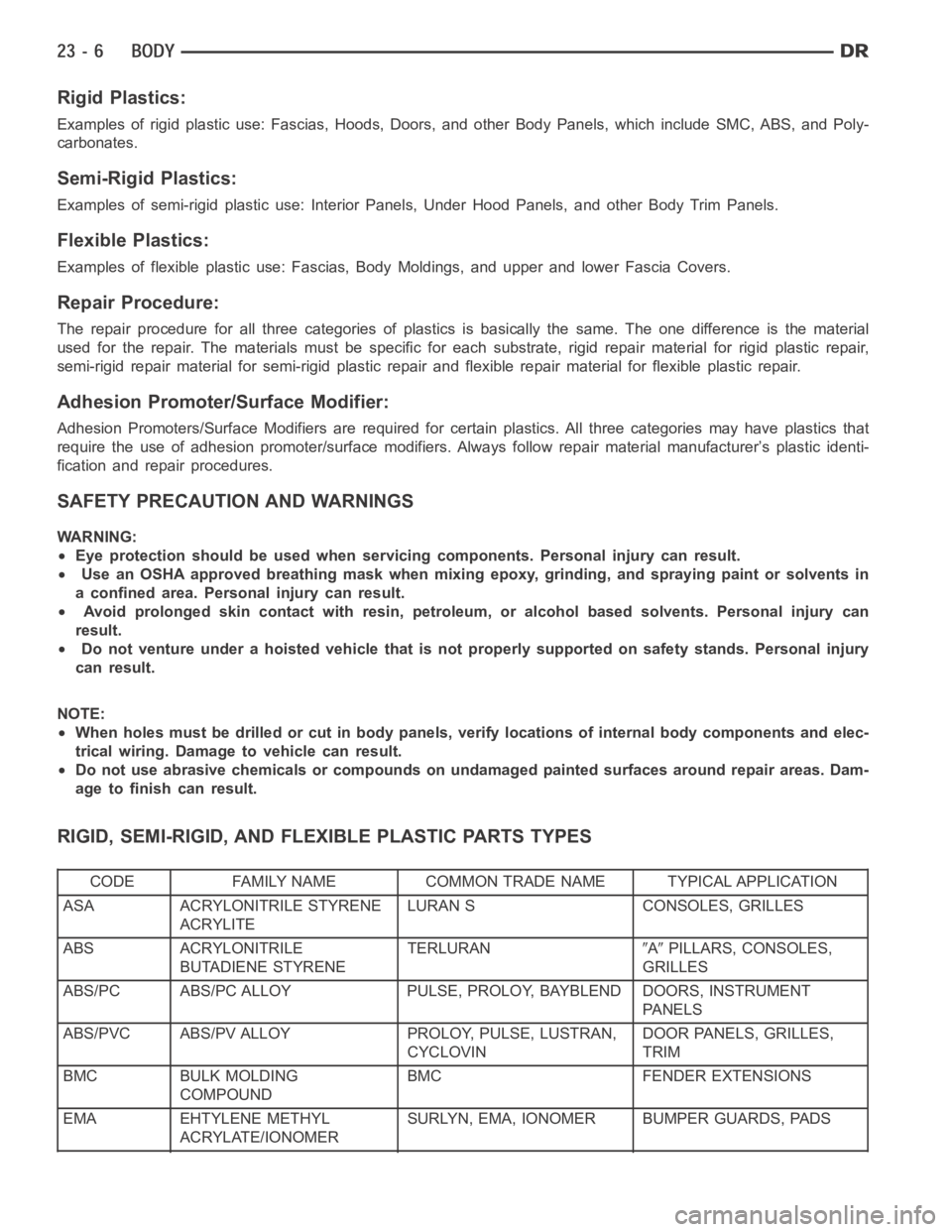
Rigid Plastics:
Examples of rigid plastic use: Fascias, Hoods, Doors, and other Body Panels, which include SMC, ABS, and Poly-
carbonates.
Semi-Rigid Plastics:
Examples of semi-rigid plastic use: Interior Panels, Under Hood Panels, and other Body Trim Panels.
Flexible Plastics:
Examples of flexible plastic use: Fascias, Body Moldings, and upper and lower Fascia Covers.
Repair Procedure:
The repair procedure for all three categories of plastics is basically thesame. The one difference is the material
used for the repair. The materials must be specific for each substrate, rigid repair material for rigid plastic repair,
semi-rigid repair material for semi-rigid plastic repair and flexible repair material for flexible plastic repair.
Adhesion Promoter/Surface Modifier:
Adhesion Promoters/Surface Modifiers are required for certain plastics. All three categories may have plastics that
require the use of adhesion promoter/surface modifiers. Always follow repair material manufacturer’s plastic identi-
fication and repair procedures.
SAFETY PRECAUTION AND WARNINGS
WARNING:
Eye protection should be used when servicing components. Personal injurycan result.
Use an OSHA approved breathing mask when mixing epoxy, grinding, and spraying paint or solvents in
a confined area. Personal injury can result.
Avoid prolonged skin contact with resin, petroleum, or alcohol based solvents. Personal injury can
result.
Do not venture under a hoisted vehicle that is not properly supported on safety stands. Personal injury
can result.
NOTE:
When holes must be drilled or cut in bodypanels, verify locations of internal body components and elec-
trical wiring. Damage to vehicle can result.
Do not use abrasive chemicals or compounds on undamaged painted surfaces around repair areas. Dam-
age to finish can result.
RIGID, SEMI-RIGID, AND FLEXIBLE PLASTIC PARTS TYPES
CODE FAMILY NAME COMMON TRADE NAME TYPICAL APPLICATION
ASA ACRYLONITRILE STYRENE
ACRYLITELURAN S CONSOLES, GRILLES
ABS ACRYLONITRILE
BUTADIENE STYRENETERLURAN
APILLARS, CONSOLES,
GRILLES
ABS/PC ABS/PC ALLOY PULSE, PROLOY, BAYBLEND DOORS, INSTRUMENT
PA N E L S
ABS/PVC ABS/PV ALLOY PROLOY, PULSE, LUSTRAN,
CYCLOVINDOOR PANELS, GRILLES,
TRIM
BMC BULK MOLDING
COMPOUNDBMC FENDER EXTENSIONS
EMA EHTYLENE METHYL
ACRYLATE/IONOMERSURLYN, EMA, IONOMER BUMPER GUARDS, PADS
Page 4344 of 5267

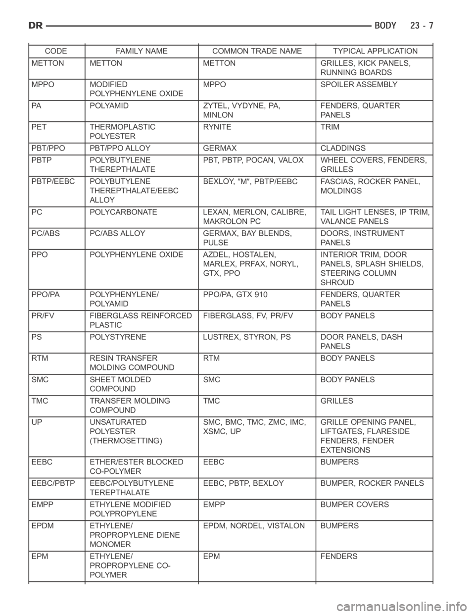
CODE FAMILY NAME COMMON TRADE NAME TYPICAL APPLICATION
METTON METTON METTON GRILLES, KICK PANELS,
RUNNING BOARDS
MPPO MODIFIED
POLYPHENYLENE OXIDEMPPO SPOILER ASSEMBLY
PA POLYAMID ZYTEL, VYDYNE, PA,
MINLONFENDERS, QUARTER
PA N E L S
PET THERMOPLASTIC
POLYESTERRYNITE TRIM
PBT/PPO PBT/PPO ALLOY GERMAX CLADDINGS
PBTP POLYBUTYLENE
THEREPTHALATEPBT, PBTP, POCAN, VALOX WHEEL COVERS, FENDERS,
GRILLES
PBTP/EEBC POLYBUTYLENE
THEREPTHALATE/EEBC
ALLOYBEXLOY,
M, PBTP/EEBC FASCIAS, ROCKER PANEL,
MOLDINGS
PC POLYCARBONATE LEXAN, MERLON, CALIBRE,
MAKROLON PCTAIL LIGHT LENSES, IP TRIM,
VA L A N C E PA N E L S
PC/ABS PC/ABS ALLOY GERMAX, BAY BLENDS,
PULSEDOORS, INSTRUMENT
PA N E L S
PPO POLYPHENYLENE OXIDE AZDEL, HOSTALEN,
MARLEX, PRFAX, NORYL,
GTX, PPOINTERIOR TRIM, DOOR
PANELS, SPLASH SHIELDS,
STEERING COLUMN
SHROUD
PPO/PA POLYPHENYLENE/
POLYAMIDPPO/PA, GTX 910 FENDERS, QUARTER
PA N E L S
PR/FV FIBERGLASS REINFORCED
PLASTICFIBERGLASS, FV, PR/FV BODY PANELS
PS POLYSTYRENE LUSTREX, STYRON, PS DOOR PANELS, DASH
PA N E L S
RTM RESIN TRANSFER
MOLDING COMPOUNDRTM BODY PANELS
SMC SHEET MOLDED
COMPOUNDSMC BODY PANELS
TMC TRANSFER MOLDING
COMPOUNDTMC GRILLES
UP UNSATURATED
POLYESTER
(THERMOSETTING)SMC, BMC, TMC, ZMC, IMC,
XSMC, UPGRILLE OPENING PANEL,
LIFTGATES, FLARESIDE
FENDERS, FENDER
EXTENSIONS
EEBC ETHER/ESTER BLOCKED
CO-POLYMEREEBC BUMPERS
EEBC/PBTP EEBC/POLYBUTYLENE
TEREPTHALATEEEBC, PBTP, BEXLOY BUMPER, ROCKER PANELS
EMPP ETHYLENE MODIFIED
POLYPROPYLENEEMPP BUMPER COVERS
EPDM ETHYLENE/
PROPROPYLENE DIENE
MONOMEREPDM, NORDEL, VISTALON BUMPERS
EPM ETHYLENE/
PROPROPYLENE CO-
POLYMEREPM FENDERS
Page 4392 of 5267
SIDE VIEW MIRROR FLAG
REMOVAL
1. Remove the door trim panel (4) (Refer to 23 -
BODY/DOOR - FRONT/TRIM PANEL - REMOVAL).
CAUTION: Do not use a drill to remove the heat
stakes. The remaining portions of the heat stake
studs are needed for installation purposes. Failure
to follow this caution may require door trim panel
replacement.
2. Remove the heat stakes (3) using a razor knife or
equivalent.
3. Release the tabs (2) and remove the mirror flag (1)
from the door trim panel.
INSTALLATION
NOTE: Clean any excess heat stake material off of
the heat stake studs to aid in mirror flag installa-
tion.
1. Install the mirror flag (1) over the tabs (2) and
install the screws (3) into the heat stake studs.
2. Install the door trim panel (4) (Refer to 23 - BODY/
DOOR - FRONT/TRIM PANEL - INSTALLATION)
Page 4510 of 5267
STEERING COLUMN OPENING SUPPORT BRACKET
REMOVAL
1. Remove the steering column opening cover from
the instrument panel (1) (Refer to 23 - BODY/IN-
STRUMENT PANEL/STEERING COLUMN OPEN-
ING COVER - REMOVAL).
2. Remove the hood release handle from the steering
column opening support bracket (2) (Refer to 23 -
BODY/HOOD/LATCH RELEASE CABLE -
REMOVAL).
3. Disengage the retaining tabs that secure the data
link connector (3) to the steering column opening
support bracket and remove the data link connector
from the bracket.
4. Remove the two screws (4) that secure the steer-
ing column opening support bracket (3) to the
instrument panel (2).
5. Slide the steering column opening support bracket
upward to disengage the two locating tabs (1) and
remove the bracket.
Page 4511 of 5267
INSTALLATION
1. Position the steering column opening bracket (3)
onto the instrument panel (2) and engage to the
two locating tabs (1).
2. Install the two screws (4) that secure the steering
column opening bracket to the instrument panel.
Tighten the screws to 2.2 Nꞏm (20 in. lbs.).
3. Position the data link connector (3) into the open-
ing in the steering column opening bracket (2) and
fully engage the retaining tabs that secure the con-
nector to the bracket.
4. Install the hood release handle (Refer to 23 -
BODY/HOOD/LATCH RELEASE CABLE - INSTAL-
LATION).
5. Install the steering column opening cover onto the
instrument panel (1) (Refer to 23 - BODY/INSTRU-
MENT PANEL/STEERING COLUMN OPENING
COVER - INSTALLATION).
Page 4515 of 5267
4WD FLOOR SHIFT BOOT
REMOVAL
1. Using a small flat-bladed tool, remove the insert (2)
from the top of the shift knob (1).
2. Remove the nut (3) that secures the shift knob to
the gear shift lever.
3. Remove the gear shift knob (2).
4. Using a trim stick C-4755 or equivalent, disengage
the retaining tabs that secure the gear shift boot (3)
to the floor console (1) and remove the boot.
INSTALLATION
1. Position the gear shift boot (3) over the gear shift
lever.
2. Engage the retaining tabs that secure the gear shift
boot to the floor console (1).
3. Install the shift knob (2) over the gear shift lever.
Page 4519 of 5267

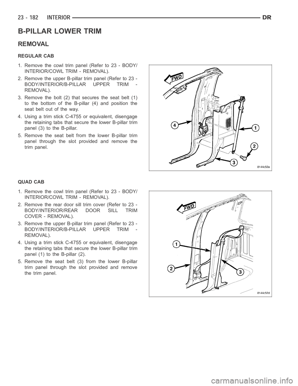
B-PILLAR LOWER TRIM
REMOVAL
REGULAR CAB
1. Remove the cowl trim panel (Refer to 23 - BODY/
INTERIOR/COWL TRIM - REMOVAL).
2. Remove the upper B-pillar trim panel (Refer to 23 -
BODY/INTERIOR/B-PILLAR UPPER TRIM -
REMOVAL).
3. Remove the bolt (2) that secures the seat belt (1)
to the bottom of the B-pillar (4) and position the
seat belt out of the way.
4. Using a trim stick C-4755 or equivalent, disengage
the retaining tabs that secure the lower B-pillar trim
panel (3) to the B-pillar.
5. Remove the seat belt from the lower B-pillar trim
panel through the slot provided and remove the
trim panel.
QUAD CAB
1. Remove the cowl trim panel (Refer to 23 - BODY/
INTERIOR/COWL TRIM - REMOVAL).
2. Removethereardoorsilltrimcover(Referto23-
BODY/INTERIOR/REAR DOOR SILL TRIM
COVER - REMOVAL).
3. Remove the upper B-pillar trim panel (Refer to 23 -
BODY/INTERIOR/B-PILLAR UPPER TRIM -
REMOVAL).
4. Using a trim stick C-4755 or equivalent, disengage
the retaining tabs that secure the lower B-pillar trim
panel (1) to the B-pillar (2).
5. Remove the seat belt (3)from the lower B-pillar
trim panel through the slot provided and remove
the trim panel.