2006 DODGE RAM SRT-10 ABS
[x] Cancel search: ABSPage 5061 of 5267
ACTUATOR-BLEND DOOR
DESCRIPTION
The blend door actuators are reversible, 12-volt direct
current (DC), servo motors. Models with the single
zone heating-A/C system have a single blend-air door,
which is controlled by a single blend door actuator.
Models with the dual zone system have two blend-air
doors, which are controlled by two blend door actua-
tors.
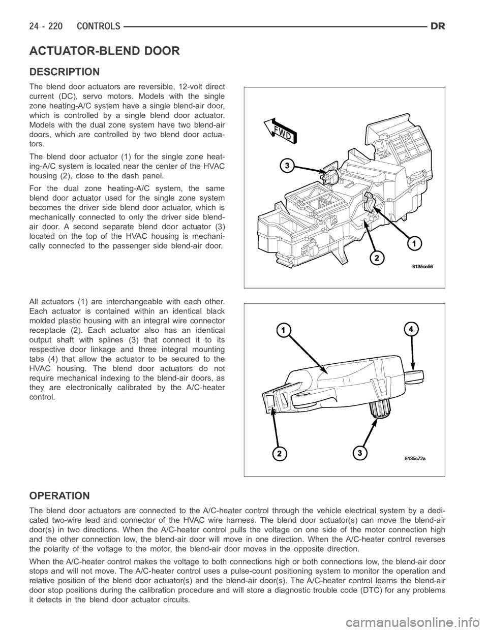
The blend door actuator (1) for the single zone heat-
ing-A/C system is located near the center of the HVAC
housing (2), close to the dash panel.
For the dual zone heating-A/C system, the same
blend door actuator used for the single zone system
becomes the driver side blend door actuator, which is
mechanically connected to only the driver side blend-
air door. A second separate blend door actuator (3)
located on the top of the HVAC housing is mechani-
cally connected to the passenger side blend-air door.
All actuators (1) are interchangeable with each other.
Each actuator is contained within an identical black
molded plastic housing with an integral wire connector
receptacle (2). Each actuator also has an identical
output shaft with splines (3) that connect it to its
respective door linkage and three integral mounting
tabs (4) that allow the actuator to be secured to the
HVAC housing. The blend door actuators do not
require mechanical indexing to the blend-air doors, as
they are electronically calibrated by the A/C-heater
control.
OPERATION
The blend door actuators are connected to the A/C-heater control through the vehicle electrical system by a dedi-
cated two-wire lead and connector of the HVAC wire harness. The blend door actuator(s) can move the blend-air
door(s) in two directions. When the A/C-heater control pulls the voltage on one side of the motor connection high
and the other connection low, the blend-air door will move in one direction. When the A/C-heater control reverses
the polarity of the voltage to the motor, the blend-air door moves in the opposite direction.
When the A/C-heater control makes the voltage to both connections high or both connections low, the blend-air door
stops and will not move. The A/C-heater control uses a pulse-count positioning system to monitor the operation and
relative position of the blend door actuator(s) and the blend-air door(s). The A/C-heater control learns the blend-air
door stop positions during the calibration procedure and will store a diagnostic trouble code (DTC) for any problems
it detects in the blend door actuator circuits.
Page 5066 of 5267
ACTUATOR-MODE DOOR
DESCRIPTION
The mode door actuators are reversible, 12-volt direct
current (DC) servo motors.The heating-A/C systems
on this vehicle use two mode door actuators. One for
the panel/floor-air door and one for the defrost-air
door.
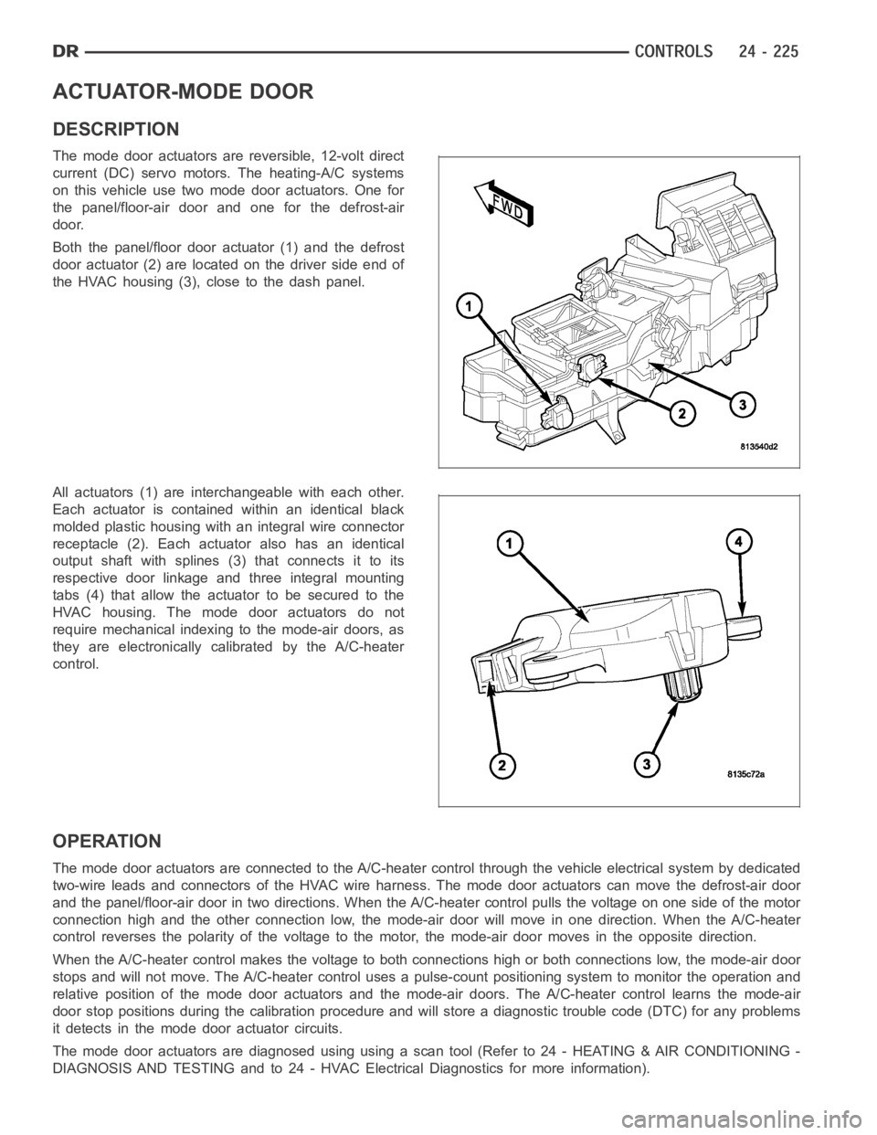
Both the panel/floor door actuator (1) and the defrost
door actuator (2) are located on the driver side end of
the HVAC housing (3), close to the dash panel.
All actuators (1) are interchangeable with each other.
Each actuator is contained within an identical black
molded plastic housing with an integral wire connector
receptacle (2). Each actuator also has an identical
output shaft with splines (3) that connects it to its
respective door linkage and three integral mounting
tabs (4) that allow the actuator to be secured to the
HVAC housing. The mode door actuators do not
require mechanical indexing to the mode-air doors, as
they are electronically calibrated by the A/C-heater
control.
OPERATION
The mode door actuators are connectedto the A/C-heater control through the vehicle electrical system by dedicated
two-wire leads and connectors of the HVAC wire harness. The mode door actuators can move the defrost-air door
and the panel/floor-air door in two directions. When the A/C-heater control pulls the voltage on one side of the motor
connection high and the other connection low, the mode-air door will move in one direction. When the A/C-heater
control reverses the polarity of the voltage to the motor, the mode-air door moves in the opposite direction.
When the A/C-heater control makes the voltage to both connections high or both connections low, the mode-air door
stops and will not move. The A/C-heater control uses a pulse-count positioning system to monitor the operation and
relative position of the mode door actuators and the mode-air doors. The A/C-heater control learns the mode-air
door stop positions during the calibration procedure and will store a diagnostic trouble code (DTC) for any problems
it detects in the mode door actuator circuits.
The mode door actuators are diagnosed using using a scan tool (Refer to 24 - HEATING & AIR CONDITIONING -
DIAGNOSIS AND TESTING and to 24 - HVAC Electrical Diagnostics for more information).
Page 5070 of 5267
ACTUATOR-RECIRCULATION DOOR
DESCRIPTION
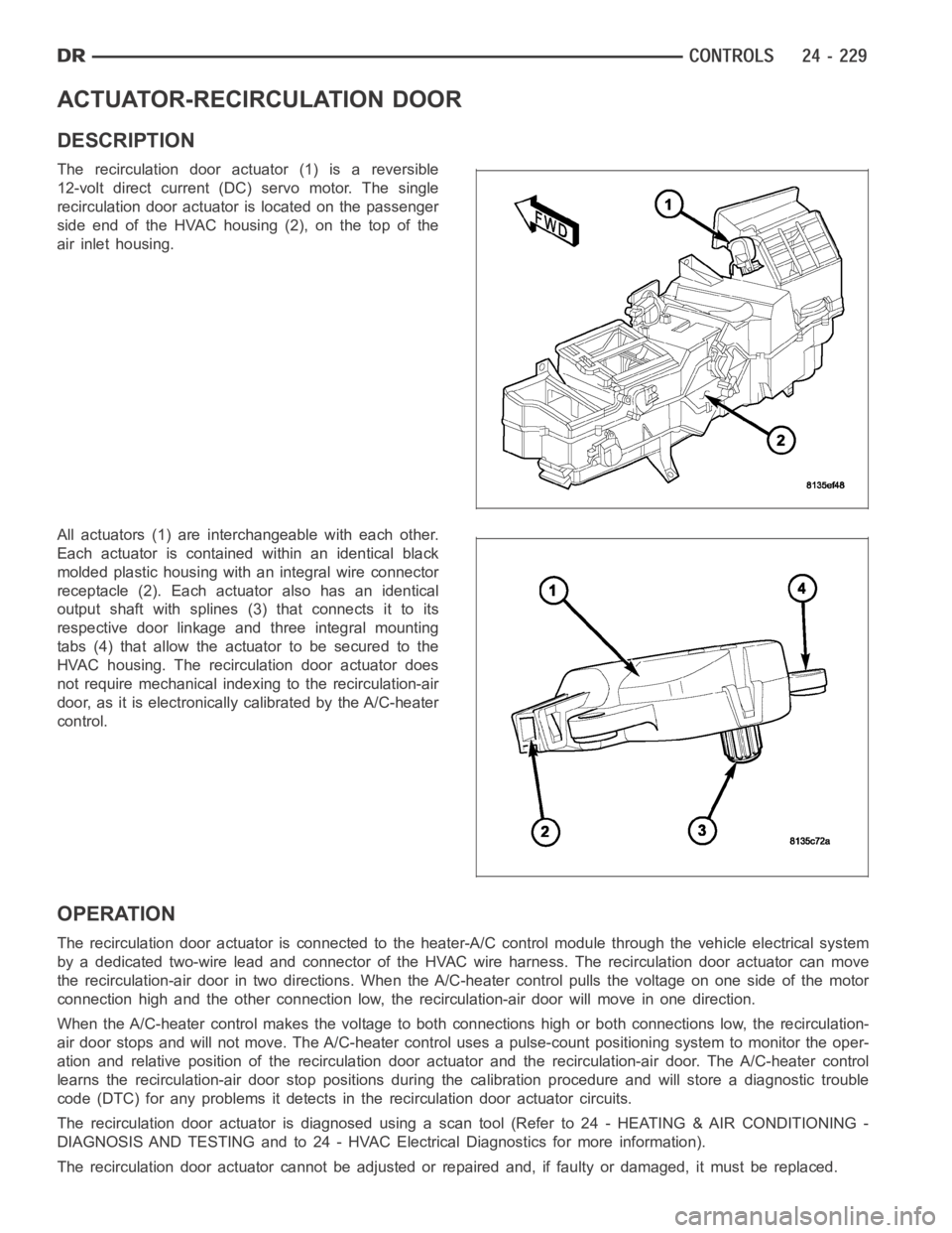
The recirculation door actuator (1) is a reversible
12-volt direct current (DC)servo motor. The single
recirculation door actuator is located on the passenger
side end of the HVAC housing (2), on the top of the
air inlet housing.
All actuators (1) are interchangeable with each other.
Each actuator is contained within an identical black
molded plastic housing with an integral wire connector
receptacle (2). Each actuator also has an identical
output shaft with splines (3) that connects it to its
respective door linkage and three integral mounting
tabs (4) that allow the actuator to be secured to the
HVAC housing. The recirculation door actuator does
not require mechanical indexing to the recirculation-air
door, as it is electronically calibrated by the A/C-heater
control.
OPERATION
The recirculation door actuator is connected to the heater-A/C control module through the vehicle electrical system
by a dedicated two-wire lead and connector of the HVAC wire harness. The recirculation door actuator can move
the recirculation-air door in two directions. When the A/C-heater control pulls the voltage on one side of the motor
connection high and the other connection low, the recirculation-air doorwill move in one direction.
When the A/C-heater control makes the voltage to both connections high or both connections low, the recirculation-
air door stops and will not move. The A/C-heater control uses a pulse-countpositioning system to monitor the oper-
ation and relative position of the recirculation door actuator and the recirculation-air door. The A/C-heater control
learns the recirculation-air door stop positions during the calibrationprocedure and will store a diagnostic trouble
code (DTC) for any problems it detects in the recirculation door actuator circuits.
The recirculation door actuator is diagnosed using a scan tool (Refer to 24- HEATING & AIR CONDITIONING -
DIAGNOSIS AND TESTING and to 24 - HVAC Electrical Diagnostics for more information).
The recirculation door actuator cannot be adjusted or repaired and, if faulty or damaged, it must be replaced.
Page 5081 of 5267
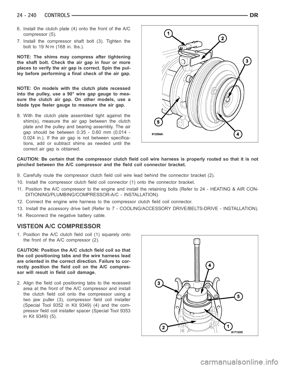
6. Install the clutch plate (4) onto the front of the A/C
compressor (5).
7. Install the compressor shaft bolt (3). Tighten the
bolt to 19 Nꞏm (168 in. lbs.).
NOTE: The shims may compress after tightening
the shaft bolt. Check the air gap in four or more
places to verify the air gap is correct. Spin the pul-
ley before performing a final check of the air gap.
NOTE: On models with the clutch plate recessed
intothepulley,usea90°wiregapgaugetomea-
sure the clutch air gap. On other models, use a
blade type feeler gauge to measure the air gap.
8. With the clutch plate assembled tight against the
shim(s), measure the air gap between the clutch
plate and the pulley and bearing assembly. The air
gap should be between 0.35 - 0.60 mm (0.014 -
0.024 in.). If the air gap is not between specifica-
tions, add or subtract shims as needed until the
correct air gap is obtained.
CAUTION: Be certain that the compressor clutch field coil wire harness is properly routed so that it is not
pinched between the A/C compressor and the field coil connector bracket.
9. Carefully route the compressor clutch field coil wire lead behind the connector bracket (2).
10. Install the compressor clutch fieldcoil connector (1) onto the connector bracket.
11. Position the A/C compressor to the engine and install the retaining bolts (Refer to 24 - HEATING & AIR CON-
DITIONING/PLUMBING/COMPRESSOR-A/C - INSTALLATION).
12. Connect the engine wire harness to the compressor clutch field coil connector.
13. Install the accessory drive belt (Refer to 7 - COOLING/ACCESSORY DRIVE/BELTS-DRIVE - INSTALLATION).
14. Reconnect the negative battery cable.
VISTEON A/C COMPRESSOR
1. Position the A/C clutch field coil (1) squarely onto
the front of the A/C compressor (2).
CAUTION: Position the A/C clutch field coil so that
the coil positioning tabs and the wire harness lead
are oriented in the correct direction. Failure to cor-
rectly position the fieldcoil on the A/C compres-
sor will result in field coil damage.
2. Align the field coil positioning tabs to the recessed
area at the front of the A/C compressor and install
the clutch field coil onto the compressor using a
two jaw puller (3), compressor field coil installer
(Special Tool 9352 in Kit 9349) (4) and the com-
pressor field coil installer spacer (Special Tool 9353
in Kit 9349) (5).
Page 5107 of 5267
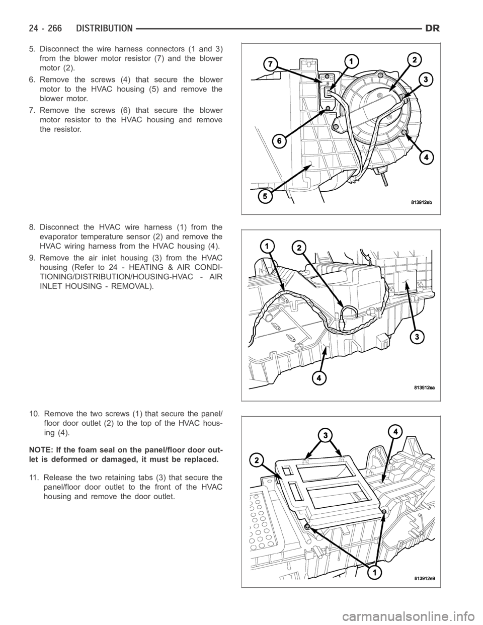
5. Disconnect the wire harness connectors (1 and 3)
from the blower motor resistor (7) and the blower
motor (2).
6. Remove the screws (4)that secure the blower
motor to the HVAC housing (5) and remove the
blower motor.
7. Remove the screws (6)that secure the blower
motor resistor to the HVAC housing and remove
the resistor.
8. Disconnect the HVAC wire harness (1) from the
evaporator temperature sensor (2) and remove the
HVAC wiring harness from the HVAC housing (4).
9. Remove the air inlet housing (3) from the HVAC
housing (Refer to 24 - HEATING & AIR CONDI-
TIONING/DISTRIBUTION/HOUSING-HVAC - AIR
INLET HOUSING - REMOVAL).
10. Remove the two screws (1) that secure the panel/
floor door outlet (2) to the top of the HVAC hous-
ing (4).
NOTE: If the foam seal on the panel/floor door out-
let is deformed or damaged, it must be replaced.
11. Release the two retaining tabs (3) that secure the
panel/floor door outlet to the front of the HVAC
housing and remove the door outlet.
Page 5108 of 5267

12. Remove the three screws (1) that secure the pan-
el/floor door assembly (2) to the top of the HVAC
housing (3) and remove the door assembly.
13. To remove the panel/floor-air doors (1) from the
panel/floor door plate (2), first carefully release
the retaining tabs of actuator coupler (3) located
on the inside surface of the door plate and pull
the actuator coupler out of the pivot shaft of the
panel/floor-air doors.
NOTE: If the seals on the air doors is deformed or
damaged, the air doors must be replaced.
14. Remove the panel/floor-air doors from the panel/
floor door plate.
Page 5110 of 5267
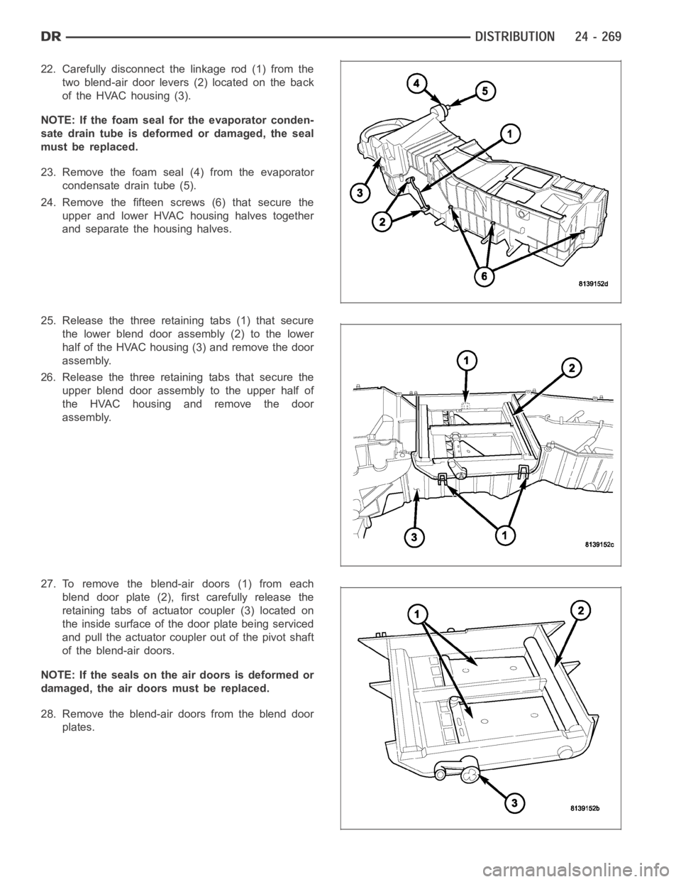
22. Carefully disconnect the linkage rod (1) from the
two blend-air door levers (2) located on the back
of the HVAC housing (3).
NOTE: If the foam seal for the evaporator conden-
sate drain tube is deformed or damaged, the seal
must be replaced.
23. Remove the foam seal (4) from the evaporator
condensate drain tube (5).
24. Remove the fifteen screws (6) that secure the
upper and lower HVAC housing halves together
and separate the housing halves.
25. Release the three retaining tabs (1) that secure
the lower blend door assembly (2) to the lower
half of the HVAC housing (3) and remove the door
assembly.
26. Release the three retaining tabs that secure the
upper blend door assembly to the upper half of
the HVAC housing and remove the door
assembly.
27. To remove the blend-air doors (1) from each
blend door plate (2), first carefully release the
retaining tabs of actuator coupler (3) located on
the inside surface of the door plate being serviced
and pull the actuator coupler out of the pivot shaft
of the blend-air doors.
NOTE: If the seals on the air doors is deformed or
damaged, the air doors must be replaced.
28. Remove the blend-air doors from the blend door
plates.
Page 5111 of 5267
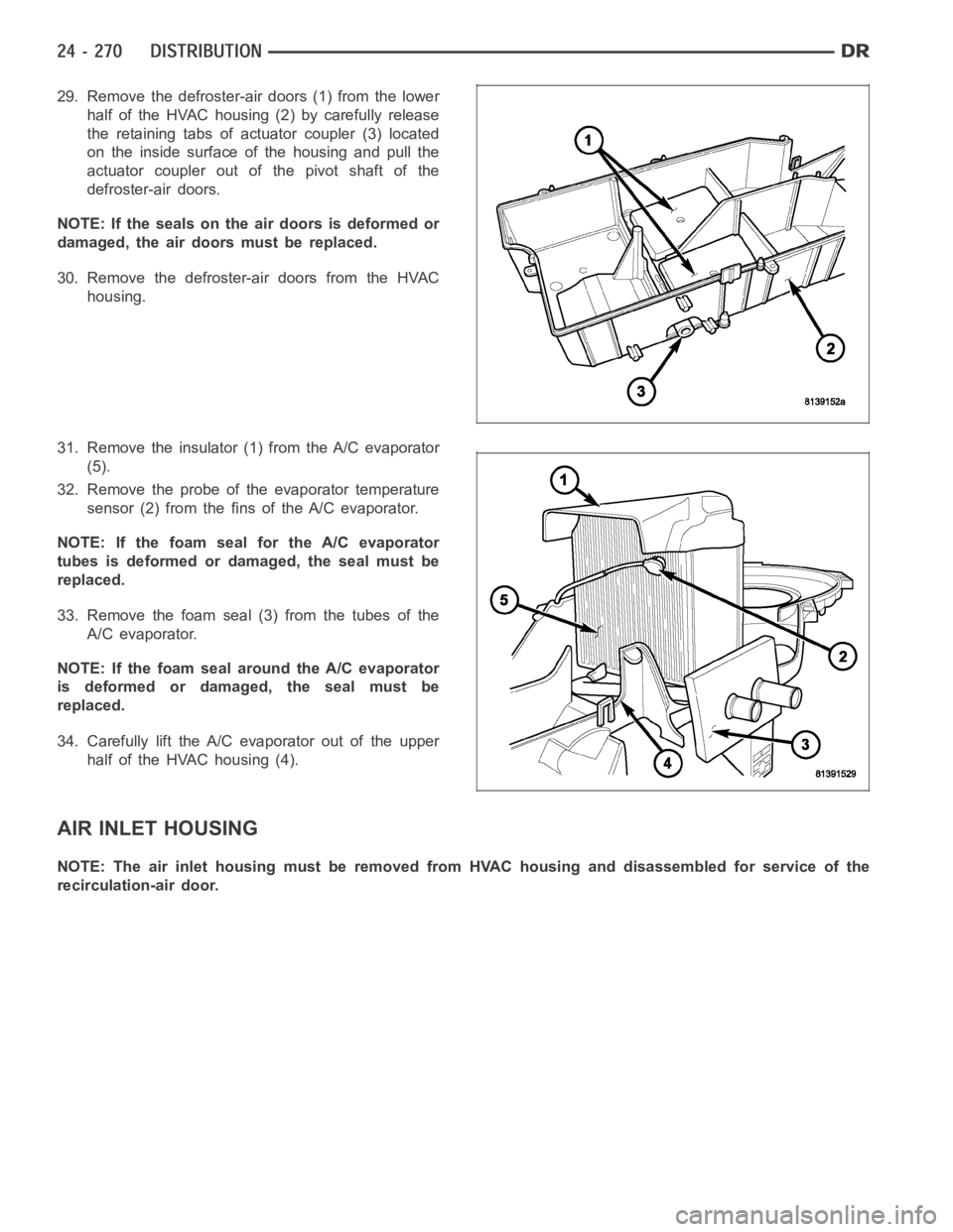
29. Remove the defroster-air doors (1) from the lower
half of the HVAC housing (2) by carefully release
the retaining tabs of actuator coupler (3) located
on the inside surface of the housing and pull the
actuator coupler out of the pivot shaft of the
defroster-air doors.
NOTE: If the seals on the air doors is deformed or
damaged, the air doors must be replaced.
30. Remove the defroster-air doors from the HVAC
housing.
31. Remove the insulator (1) from the A/C evaporator
(5).
32. Remove the probe of the evaporator temperature
sensor (2) from the fins of the A/C evaporator.
NOTE: If the foam seal for the A/C evaporator
tubes is deformed or damaged, the seal must be
replaced.
33. Remove the foam seal (3) from the tubes of the
A/C evaporator.
NOTE: If the foam seal around the A/C evaporator
is deformed or damaged, the seal must be
replaced.
34. Carefully lift the A/C evaporator out of the upper
half of the HVAC housing (4).
AIR INLET HOUSING
NOTE: The air inlet housing must be removed from HVAC housing and disassembled for service of the
recirculation-air door.