Page 1593 of 5267
SWITCH-OIL PRESSURE
DESCRIPTION
The 3 wire, solid-state engine oil pressure sensor (sending unit) is located in an engine oil pressure gallery.
OPERATION
The oil pressure sensor uses three circuits. They are:
A 5 volt power supply from the Powertrain Control Module (PCM)
A sensor ground through the PCM’s sensor return
A signal to the PCM relating to engine oil pressure
The oil pressure sensor has a 3 wire electrical function very much like the Manifold Absolute Pressure (MAP) sen-
sor. Meaning different pressures relate to different output voltages.
A 5 volt supply is sent to the sensor from the PCM to power up the sensor. The sensor returns a voltage signal
back to the PCM relating to engine oil pressure. This signal is then transferred (bussed) to the instrument panel on
either a CCD or PCI bus circuit (depending on vehicle line) to operate the oil pressure gauge and the check gauges
lamp. Ground for the sensor is provided by the PCM through a low-noise sensor return.
REMOVAL
1. Disconnect the negative cable from the battery.
2. Raise vehicle on hoist.
3. Remove front splash shield.
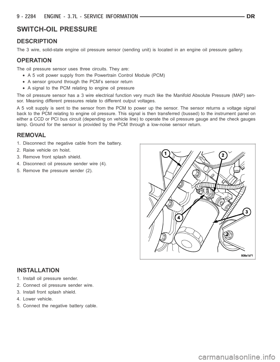
4. Disconnect oil pressure sender wire (4).
5. Remove the pressure sender (2).
INSTALLATION
1. Install oil pressure sender.
2. Connect oil pressure sender wire.
3. Install front splash shield.
4. Lower vehicle.
5. Connect the negative battery cable.
Page 1600 of 5267
MANIFOLD-INTAKE
DESCRIPTION
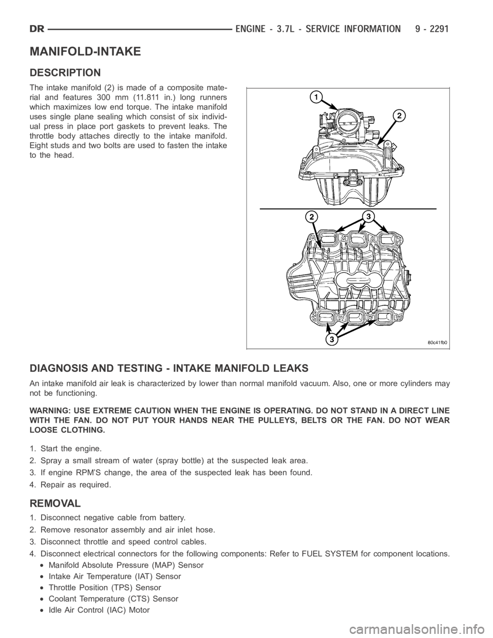
The intake manifold (2) is made of a composite mate-
rial and features 300 mm (11.811 in.) long runners
which maximizes low end torque. The intake manifold
uses single plane sealing which consist of six individ-
ual press in place port gaskets to prevent leaks. The
throttle body attaches directly to the intake manifold.
Eight studs and two bolts are used to fasten the intake
to the head.
DIAGNOSIS AND TESTING -INTAKE MANIFOLD LEAKS
An intake manifold air leak is characterized by lower than normal manifoldvacuum. Also, one or more cylinders may
not be functioning.
WARNING: USE EXTREME CAUTION WHEN THE ENGINE IS OPERATING. DO NOT STAND IN ADIRECT LINE
WITH THE FAN. DO NOT PUT YOUR HANDS NEAR THE PULLEYS, BELTS OR THE FAN. DO NOT WEAR
LOOSE CLOTHING.
1. Start the engine.
2. Spray a small stream of water (spray bottle) at the suspected leak area.
3. If engine RPM’S change, the area of the suspected leak has been found.
4. Repair as required.
REMOVAL
1. Disconnect negative cable from battery.
2. Remove resonator assembly and air inlet hose.
3. Disconnect throttle and speed control cables.
4. Disconnect electrical connectors for the following components: Referto FUEL SYSTEM for component locations.
Manifold Absolute Pressure (MAP) Sensor
Intake Air Temperature (IAT) Sensor
Throttle Position (TPS) Sensor
Coolant Temperature (CTS) Sensor
Idle Air Control (IAC) Motor
Page 1601 of 5267
5. Disconnect vapor purge hose, brake booster hose, speed control servo hose, positive crankcase ventilation
(PCV) hose.
6. Disconnect generator electrical connections.
7. Disconnect air conditioning compressor electrical connections.
8. Disconnect left and right radio suppressor straps.
9. Disconnect and remove ignition coil towers.
10. Remove top oil dipstick tube retaining bolt and ground strap.
11. Bleed fuel system (Refer to 14 - FUEL SYSTEM/FUEL DELIVERY - STANDARD PROCEDURE).
12. Remove fuel rail.
13. Remove throttle body assembly and mounting bracket.
14. Drain cooling system below coolant temperature level (Refer to 7 - COOLING - STANDARD PROCEDURE).
15. Remove the heater hoses from the engine front cover and the heater core.
16. Unclip and remove heater hoses and tubes from intake manifold.
17. Remove coolant temperature sensor (Refer to 7 - COOLING/ENGINE/ENGINE COOLANT TEMP SENSOR -
REMOVAL).
18. Remove intake manifold retaining fasteners in reverse order of tightening sequence.
19. Remove intake manifold.
INSTALLATION
1. Install intake manifold gaskets.
2. Install intake manifold.
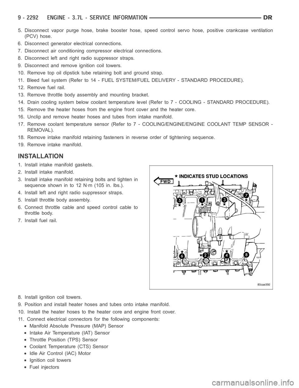
3. Install intake manifold retaining bolts and tighten in
sequence shown in to 12 Nꞏm (105 in. lbs.).
4. Install left and right radio suppressor straps.
5. Install throttle body assembly.
6. Connect throttle cable and speed control cable to
throttle body.
7. Install fuel rail.
8. Install ignition coil towers.
9. Position and install heater hoses and tubes onto intake manifold.
10. Install the heater hoses to the heater core and engine front cover.
11. Connect electrical connectors for the following components:
Manifold Absolute Pressure (MAP) Sensor
Intake Air Temperature (IAT) Sensor
Throttle Position (TPS) Sensor
Coolant Temperature (CTS) Sensor
Idle Air Control (IAC) Motor
Ignition coil towers
Fuel injectors
Page 1630 of 5267
able in three ounce tubes and has a shelf life of one year. After one year thismaterial will not properly cure. Always
inspect the package for the expiration date before use.
MOPAR
GASKET MAKER
Mopar
Gasket Maker is an anaerobic type gasket material. The material cures in the absence of air when
squeezed between two metallic surfaces. It will not cure if left in the uncovered tube. The anaerobic material is for
use between two machined surfaces. Do not use on flexible metal flanges.
MOPAR
GASKET SEALANT
Mopar
Gasket Sealant is a slow drying, permanently soft sealer. This material isrecommended for sealing
threaded fittings and gaskets against leakage of oil and coolant. Can be used on threaded and machined parts
under all temperatures. This material is used on engines with multi-layersteel (MLS) cylinder head gaskets. This
material also will prevent corrosion. Mopar
Gasket Sealant is available in a 13 oz. aerosol can or 4oz./16 oz. can
w/applicator.
FORM-IN-PLACE GASKET AND SEALER APPLICATION
Assembling parts using a form-in-place gasket requires care but it’s easier than using precut gaskets.
Mopar
Gasket Maker material should be applied sparingly 1 mm (0.040 in.) diameter or less of sealant to one
gasket surface. Be certain the material surrounds each mounting hole. Excess material can easily be wiped off.
Components should be torqued in place within 15 minutes. The use of a locating dowel is recommended during
assembly to prevent smearing material off the location.
Mopar
Engine RTV GEN II or ATF RTV gasket material should be applied in a continuous bead approximately 3
mm (0.120 in.) in diameter. All mounting holes must be circled. For corner sealing, a 3.17 or 6.35 mm (1/8 or 1/4 in.)
drop is placed in the center of the gasket contact area. Uncured sealant maybe removed with a shop towel. Com-
ponents should be torqued in place while the sealant is still wet to the touch (within 10 minutes). The usage of a
locating dowel is recommended during assembly to prevent smearing material off the location.
Mopar
Gasket Sealant in an aerosol can should be applied using a thin, even coat sprayed completely over both
surfaces to be joined, and both sides of a gasket. Then proceed with assembly. Material in a can w/applicator can
be brushed on evenly over the sealing surfaces. Material in an aerosol can shouldbeusedonengineswithmulti-
layer steel gaskets.
REMOVAL
NOTE:Thisprocedureappliestoboththe4X2and4X4vehicles,stepsthatapply to the 4X4 vehicle only,
are identified.
1. Release fuel rail pressure (Refer to 14 - FUEL SYSTEM/FUEL DELIVERY - STANDARD PROCEDURE) then
disconnect the fuel supply quick connect fitting at the fuel rail (Refer to14 - FUEL SYSTEM/FUEL DELIVERY/
QUICK CONNECT FITTING - STANDARD PROCEDURE).
2. Disconnect the battery negative and positive cables.
3. Raise vehicle on hoist.
4. Remove exhaust crossover pipe from exhaust manifolds.
5.4X4 vehiclesDisconnect axle vent tube from left side engine mount.
6. Remove the through bolt retaining nut and bolt from both the left and right side engine mounts.
7.4X4 vehiclesRemove locknut from left and right side engine mount brackets.
8. Disconnect two ground straps from the lower left hand side and one groundstrap from the lower right hand side
of the engine.
Page 1634 of 5267
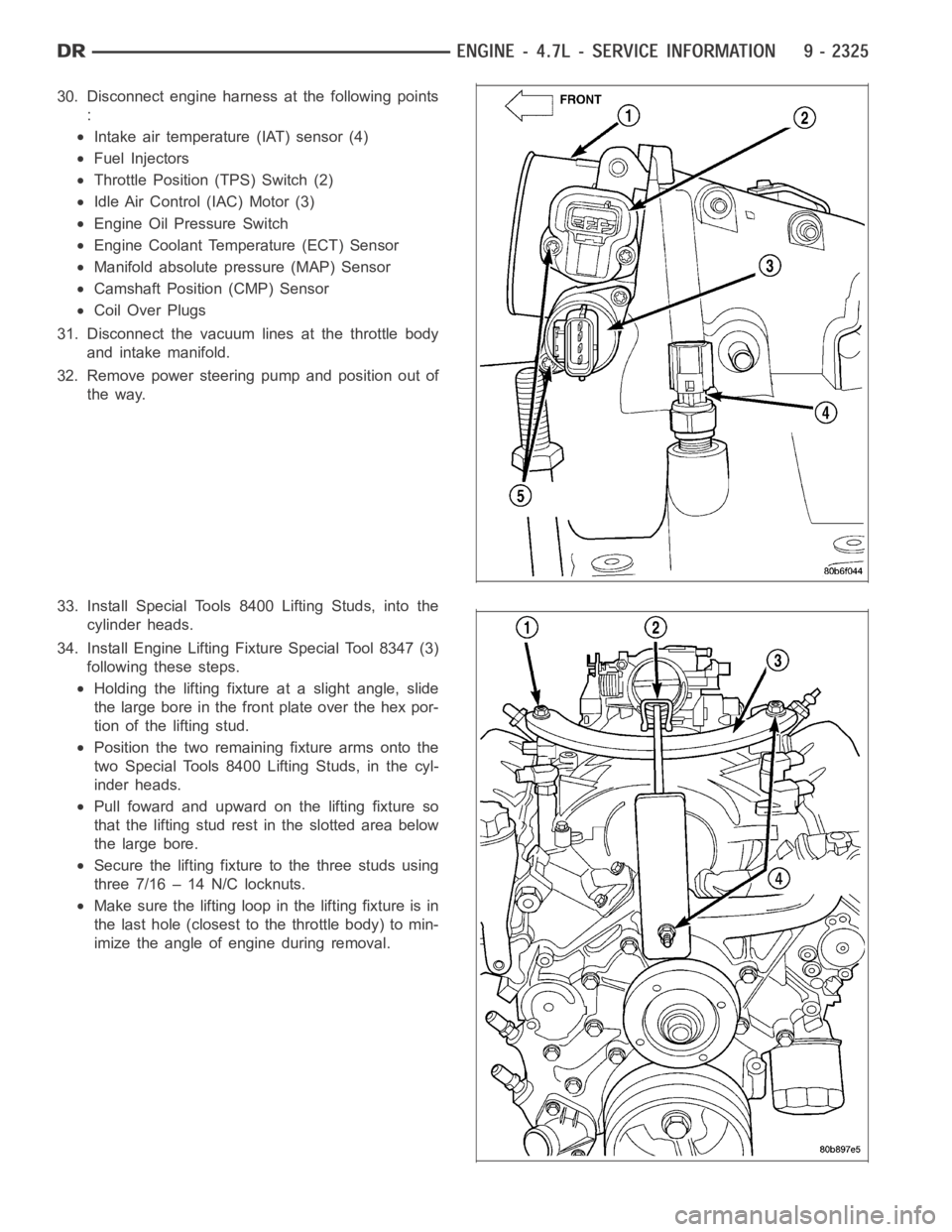
30. Disconnect engine harness at the following points
:
Intake air temperature (IAT) sensor (4)
Fuel Injectors
Throttle Position (TPS) Switch (2)
Idle Air Control (IAC) Motor (3)
Engine Oil Pressure Switch
Engine Coolant Temperature (ECT) Sensor
Manifold absolute pressure (MAP) Sensor
Camshaft Position (CMP) Sensor
Coil Over Plugs
31. Disconnect the vacuum lines at the throttle body
and intake manifold.
32. Remove power steering pump and position out of
the way.
33. Install Special Tools 8400 Lifting Studs, into the
cylinder heads.
34. Install Engine Lifting Fixture Special Tool 8347 (3)
following these steps.
Holding the lifting fixture at a slight angle, slide
the large bore in the front plate over the hex por-
tion of the lifting stud.
Position the two remaining fixture arms onto the
two Special Tools 8400 Lifting Studs, in the cyl-
inder heads.
Pull foward and upward on the lifting fixture so
that the lifting stud rest in the slotted area below
the large bore.
Secure the lifting fixture to the three studs using
three 7/16 – 14 N/C locknuts.
Make sure the lifting loop in the lifting fixture is in
the last hole (closest to the throttle body) to min-
imize the angle of engine during removal.
Page 1637 of 5267
6. Position generator wiring behind the oil dipstick
tube, then install the oil dipstick tube upper mount-
ing bolt.
7. Connect both left (2) and right (3) side body ground
straps.
8. Install power steering pump.
9. Connect fuel supply line quick connect fitting (Refer
to 14 - FUEL SYSTEM/FUEL DELIVERY/QUICK
CONNECT FITTING - STANDARD PROCEDURE).
10. Connect the vacuum lines at the throttle body and
intake manifold.
11. Connect engine harness at the following points :
Intake Air Temperature (IAT) Sensor (4)
Idle Air Control (IAC) Motor (3)
Fuel Injectors
Throttle Position (TPS) Switch (2)
Engine Oil Pressure Switch
Engine Coolant Temperature (ECT) Sensor
Manifold Absolute Pressure (MAP) Sensor
Camshaft Position (CMP) Sensor
Coil Over Plugs
Page 1651 of 5267
ELEMENT - AIR CLEANER
REMOVAL
Filter Element Only
1. Housing removal is not necessary for element (fil-
ter) replacement.
2. Loosen clamp and disconnect air duct at air
cleaner cover.
3. Pry over 4 spring clips (5) from housing cover (3)
(spring clips retain cover to housing).
4. Release housing cover (3) from locating tabs on
housing and remove cover.
5. Remove air cleaner element (filter) from housing.
6. Clean inside of housing before replacing element.
Housing Assembly
1. Loosen clamp and disconnect air duct at air
cleaner cover.
2. Lift entire housing (1) assembly from 4 locating
pins (2).
Page 1652 of 5267
INSTALLATION
1. Install filter element into housing.
2. Position housing cover into housing locating tabs.
3. Pry up 4 spring clips and lock cover to housing.
4. Install air duct to air cleaner cover and tighten hose clamp to 3 Nꞏm (30 in.lbs.)torque.
5. If any other hose clamps were removed from air intake system, tighten themto3.4Nꞏm(30in.lbs.)torque.
6. If any bolts were removed from air resonator housing or air intake tubing, tighten them to 4.5 Nꞏm (40 in. lbs.)
torque.