2006 DODGE RAM SRT-10 oil change
[x] Cancel search: oil changePage 1997 of 5267
LUBRICATION
DESCRIPTION
A gear driven gerotor type oil pump is mounted behind the front gear cover inthe lower right portion on the engine.
OPERATION
A gerotor style oil pump draws oil from the crankcase through the suction tube and delivers it through the block
where it enters the oil cooler cover and pressure regulator valve. When oilpressure exceeds 517 kPa (75 PSI), the
valve opens exposing the dump port, which routes excess oil back to the oil pump.
At the same time, oil is directed to a cast in passage in the oil cooler cover,leading to the oil cooler element. As the
oil travels through the element plates, it is cooled by engine coolant traveling past the outside of the plates. It is
then routed to the oil filter head and through a full flow oil filter. If a plugged filter is encountered, the filter by-pass
valve opens, allowing unfiltered oil to lubricate the engine. This condition can be avoided by frequent oil and filter
changes, per the maintenance schedules found in the owners manual. The by-pass valve is calibrated to open when
it sees a pressure drop of more than 345 kPa (50 psi) across the oil filter.
The oil filter head then divides the oil between the engine and the turbocharger. The turbocharger receives filtered,
cooled and pressurized oil through a supply line from the filter head. The oil lubricates the turbocharger and returns
to the pan by way of a drain tube connecting the bottom of the turbocharger toa tube in the cylinder block.
Page 2002 of 5267
OIL
STANDARD PROCEDURE
STANDARD PROCEDURE - ENGINE OIL LEVEL
CAUTION: Do not overfill crankcase with engine
oil, oil foaming and oil pressure loss can result.
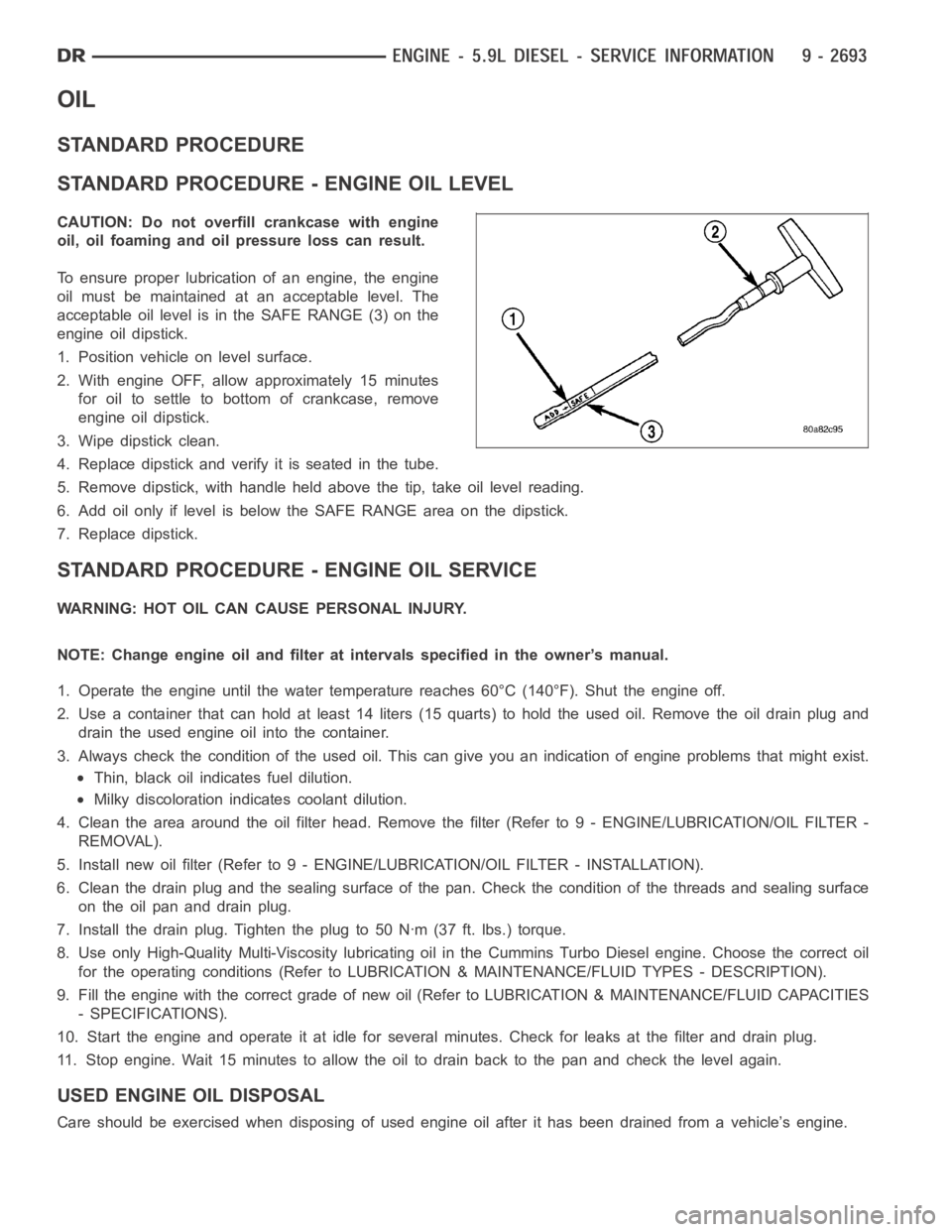
To ensure proper lubrication of an engine, the engine
oil must be maintained at an acceptable level. The
acceptable oil level is in the SAFE RANGE (3) on the
engine oil dipstick.
1. Position vehicle on level surface.
2. With engine OFF, allow approximately 15 minutes
for oil to settle to bottom of crankcase, remove
engine oil dipstick.
3. Wipe dipstick clean.
4. Replace dipstick and verify it is seated in the tube.
5. Remove dipstick, with handle held above the tip, take oil level reading.
6. Add oil only if level is below the SAFE RANGE area on the dipstick.
7. Replace dipstick.
STANDARD PROCEDURE - ENGINE OIL SERVICE
WARNING: HOT OIL CAN CAUSE PERSONAL INJURY.
NOTE: Change engine oil and filter at intervals specified in the owner’s manual.
1. Operate the engine until the water temperature reaches 60°C (140°F). Shut the engine off.
2. Use a container that can hold at least 14 liters (15 quarts) to hold the used oil. Remove the oil drain plug and
drain the used engine oil into the container.
3. Always check the condition of the used oil. This can give you an indication of engine problems that might exist.
Thin, black oil indicates fuel dilution.
Milky discoloration indicates coolant dilution.
4. Clean the area around the oil filter head. Remove the filter (Refer to 9 - ENGINE/LUBRICATION/OIL FILTER -
REMOVAL).
5. Install new oil filter (Refer to 9 - ENGINE/LUBRICATION/OIL FILTER - INSTA L L AT I O N ) .
6. Clean the drain plug and the sealing surface of the pan. Check the condition of the threads and sealing surface
on the oil pan and drain plug.
7. Install the drain plug. Tighten the plug to 50 Nꞏm (37 ft. lbs.) torque.
8. Use only High-Quality Multi-Viscosity lubricating oil in the Cummins Turbo Diesel engine. Choose the correct oil
for the operating conditions (Refer to LUBRICATION & MAINTENANCE/FLUID TYPES - DESCRIPTION).
9. Fill the engine with the correct grade of new oil (Refer to LUBRICATION & MAINTENANCE/FLUID CAPACITIES
- SPECIFICATIONS).
10. Start the engine and operate it at idle for several minutes. Check for leaks at the filter and drain plug.
11. Stop engine. Wait 15 minutes to allow the oil to drain back to the pan and check the level again.
USED ENGINE OIL DISPOSAL
Care should be exercised when disposing of used engine oil after it has beendrained from a vehicle’s engine.
Page 2020 of 5267
page page
ENGINE - 8.3L - SERVICE INFORMATION
DESCRIPTION ............................. 2713
DIAGNOSIS AND TESTING
INTRODUCTION . ......................... 2714
ENGINE DIAGNOSIS - PERFORMANCE .... 2715
ENGINE DIAGNOSIS - MECHANICAL ....... 2716
CYLINDER COMPRESSION PRESSURE
TEST.................................... 2718
CYLINDER COMBUSTION PRESSURE
LEAKAGE TEST.......................... 2718
CYLINDER HEAD GASKET FAILURE
DIAGNOSIS.............................. 2719
HYDRAULIC TAPPET NOISE DIAGNOSIS . . . 2720
ENGINE OIL LEAK INSPECTION ........... 2720
STANDARD PROCEDURE
ENGINE CORE AND OIL GALLERY PLUGS . 2722
FORM-IN-PLACE GASKETS AND SEALERS . 2722
ENGINE GASKET SURFACE
PREPARATION........................... 2723
HYDROSTATIC LOCKED ENGINE .......... 2723
REMOVAL - ENGINE ASSEMBLY . . ........... 2724
INSTALLATION - ENGINE ASSEMBLY ........ 2728
SPECIFICATIONS
ENGINE ................................. 2731
TORQUE ................................. 2736
SPECIAL TOOLS
ENGINE ................................. 2738
SYSTEM-AIR INTAKE
DESCRIPTION ............................. 2741
ELEMENT-AIR CLEANER
REMOVAL ................................. 2742
INSTALLATION ............................. 2743
HOUSING-AIR CLEANER
REMOVAL ................................. 2744
INSTALLATION ............................. 2745
MOUNTS-ENGINE
REMOVAL ................................. 2746
INSTALLATION ............................. 2747
MANIFOLD-INTAKE
DIAGNOSIS AND TESTING
INTAKE MANIFOLD LEAKS ................ 2748
REMOVAL ................................. 2748
INSPECTION ............................... 2750
INSTALLATION ............................. 2751
MANIFOLD-EXHAUST
REMOVAL ................................. 2754
INSPECTION ............................... 2755
INSTALLATION ............................. 2755
HEAD(S)-CYLINDER
REMOVAL - CYLINDER HEAD(S) ............. 2757CLEANING
CLEANING AND INSPECTION............. 2758
INSTALLATION - CYLINDER HEAD(S) ........ 2758
COVER(S)-CYLINDER HEAD
REMOVAL ................................. 2760
INSTALLATION ............................. 2761
ARMS-ROCKER
REMOVAL ................................. 2762
INSTALLATION ............................. 2762
SPRINGS/SEALS-VALVE
DIAGNOSIS AND TESTING
VALVE SPRING TESTING ................. 2763
STANDARD PROCEDURE - VALVE SPRING/
SEAL SERVICE IN-CAR ................... 2763
REMOVAL ................................. 2764
INSTALLATION ............................. 2765
INTAKE/EXHAUST - VALVES/SEATS/GUIDES
STANDARD PROCEDURE - VALVE AND
VALVE SEAT - REFACING ................. 2766
INSPECTION............................... 2767
COVER-TIMING CHAIN
REMOVAL ................................. 2769
INSTALLATION ............................. 2771
TIMING CHAIN AND SPROCKETS
REMOVAL ................................. 2774
INSTALLATION ............................. 2775
LUBRICATION
DESCRIPTION ............................. 2777
OPERATION ............................... 2777
DIAGNOSIS AND TESTING
CHECKING ENGINE OIL PRESSURE ....... 2777
ENGINE OIL LEAK ........................ 2777
OIL
STANDARD PROCEDURE
CHECKING ENGINE OIL LEVEL........... 2779
ENGINE OILAND FILTER CHANGE ........ 2779
COOLER & LINES-OIL
DESCRIPTION ............................. 2781
OPERATION ............................... 2781
STANDARD PROCEDURE - OIL COOLER LINE
QUICK CONNECT FITTING DISASSEMBLY/
ASSEMBLY............................... 2781
REMOVAL ................................. 2782
INSTALLATION ............................. 2783
PAN-OIL
REMOVAL ................................. 2784
INSTALLATION ............................. 2785
PUMP-OIL
REMOVAL ................................. 2788
DISASSEMBLY . ............................ 2788
CLEANING ................................. 2789
Page 2025 of 5267
CONDITION POSSIBLE CAUSES CORRECTION
ENGINE STALLS OR
ROUGH IDLE1. Carbon buildup on throttle plate. 1. Remove throttle body and de-carbon.
2. Engine idle speed too low. 2. Check Idle Air Control circuit. Refer to
the appropriate Diagnostic Information for
IAC motor testing.
3. Worn or incorrectly gapped spark
plugs.3. Replace spark plugs or set gap.
4. Faulty or crossed ignition cables. 4. Check for correct firing order or replace
ignition cables as necessary.
5. Faulty coil(s). 5. Test and replace as necessary.
6. Intake manifold vacuum leak. 6. Inspect intake manifold gasket and
vacuum hoses. Replace as necessary.
ENGINE MISSES ON
ACCELERATION1. Worn or incorrectly gapped spark
plugs.1. Replace spark plugs or set gap.
2. Faulty ignition cables. 2. Replace ignition cables as necessary.
3. Dirt or water in fuel system. 3. Clean system and replace fuel filter.
4. Burned, warped, or pitted valves. 4. Install new or reface valves as
necessary.
5. Faulty coil(s). 5. Test and replace as necessary.
ENGINE DIAGNOSIS - MECHANICAL
CONDITION POSSIBLE CAUSES CORRECTION
NOISY VALVES 1. High or low oil level incrankcase. 1. Check for correct oil level. Adjust oil level
by draining or adding as needed.
2. Thin or diluted oil. 2. Change oil and filter.
3. Low oil pressure. 3. Check engine oil level. If OK, perform oil
pressure test. (Refer to 9 - ENGINE/
LUBRICATION - DIAGNOSIS AND
TESTING).
4. Dirt in tappets/lash adjusters. 4. Clean/replace hydraulic tappets/lash
adjusters.
5. Bent push rod(s). 5. Replace push rod(s) as necessary.
6. Worn rocker arms. 6. Replace worn rocker arms and inspect
oil supply to rocker arms.
7. Worn tappets/lash adjusters. 7. Replace hydraulic tappets/hydrauliclash
adjusters.
8. Worn valve guides. 8. Ream and install new valves with
oversize stems.
9. Excessive runout of valve seats
on valve faces.9. Grind valve seats and valves.
Page 2026 of 5267
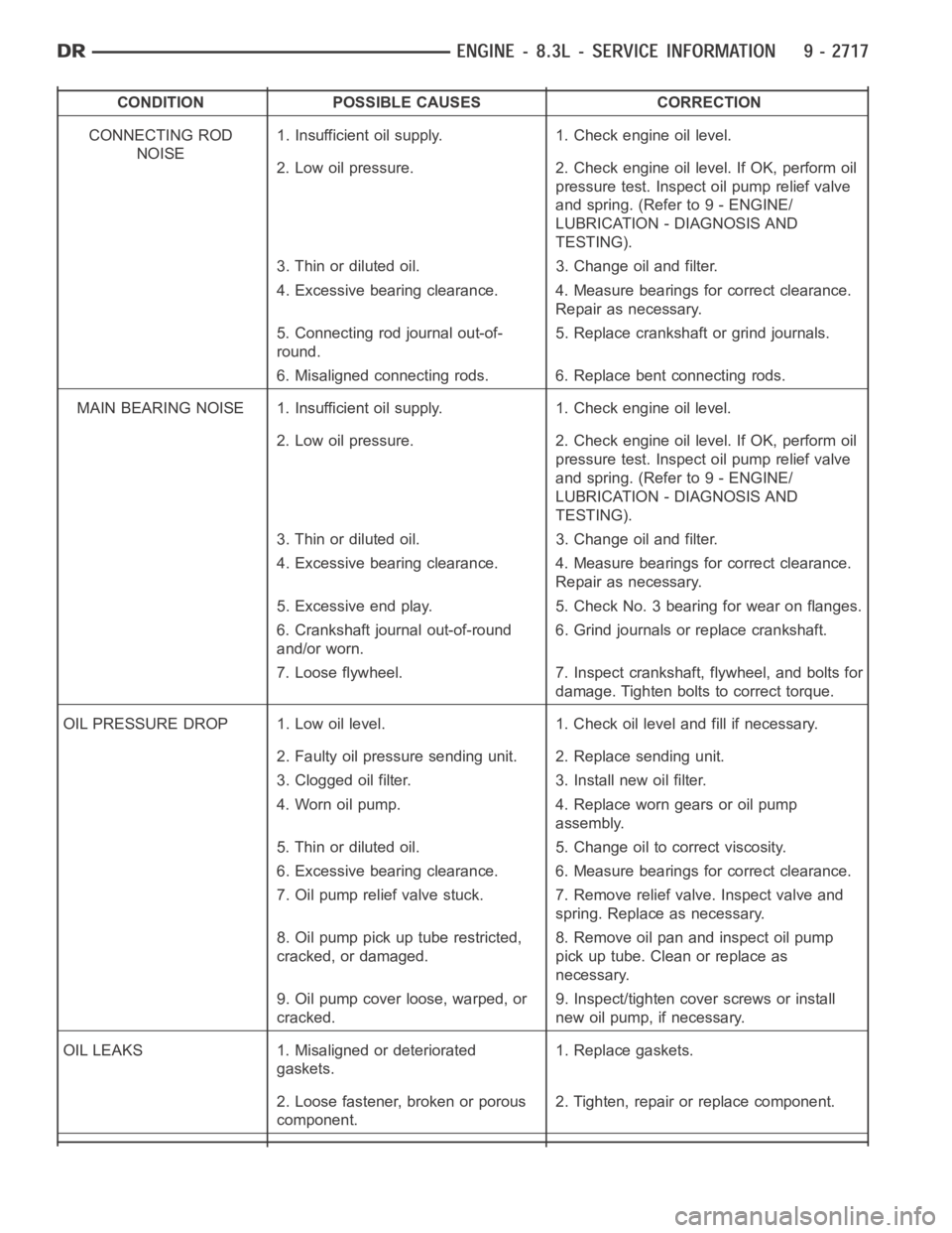
CONDITION POSSIBLE CAUSES CORRECTION
CONNECTING ROD
NOISE1. Insufficient oil supply. 1. Check engine oil level.
2. Low oil pressure. 2. Check engine oil level. If OK, perform oil
pressure test. Inspect oil pump relief valve
and spring. (Refer to 9 - ENGINE/
LUBRICATION - DIAGNOSIS AND
TESTING).
3. Thin or diluted oil. 3. Change oil and filter.
4. Excessive bearing clearance. 4. Measure bearings for correct clearance.
Repair as necessary.
5. Connecting rod journal out-of-
round.5. Replace crankshaft or grind journals.
6. Misaligned connecting rods. 6. Replace bent connecting rods.
MAIN BEARING NOISE 1. Insufficient oil supply. 1. Check engine oil level.
2. Low oil pressure. 2. Check engine oil level. If OK, perform oil
pressure test. Inspect oil pump relief valve
and spring. (Refer to 9 - ENGINE/
LUBRICATION - DIAGNOSIS AND
TESTING).
3. Thin or diluted oil. 3. Change oil and filter.
4. Excessive bearing clearance. 4. Measure bearings for correct clearance.
Repair as necessary.
5. Excessive end play. 5. Check No. 3 bearing for wear on flanges.
6. Crankshaft journal out-of-round
and/or worn.6. Grind journals or replace crankshaft.
7. Loose flywheel. 7. Inspect crankshaft, flywheel, and bolts for
damage. Tighten bolts to correct torque.
OIL PRESSURE DROP 1. Low oil level. 1. Check oil level and fill if necessary.
2. Faulty oil pressure sending unit. 2. Replace sending unit.
3. Clogged oil filter. 3. Install new oil filter.
4. Worn oil pump. 4. Replace worn gears or oil pump
assembly.
5. Thin or diluted oil. 5. Change oil to correct viscosity.
6. Excessive bearing clearance. 6. Measure bearings for correct clearance.
7. Oil pump relief valve stuck. 7. Remove relief valve. Inspect valve and
spring. Replace as necessary.
8. Oil pump pick up tube restricted,
cracked, or damaged.8. Remove oil pan and inspect oil pump
pick up tube. Clean or replace as
necessary.
9. Oil pump cover loose, warped, or
cracked.9. Inspect/tighten cover screws or install
new oil pump, if necessary.
OIL LEAKS 1. Misaligned or deteriorated
gaskets.1. Replace gaskets.
2. Loose fastener, broken or porous
component.2. Tighten, repair or replace component.
Page 2088 of 5267
OIL
STANDARD PROCEDURE
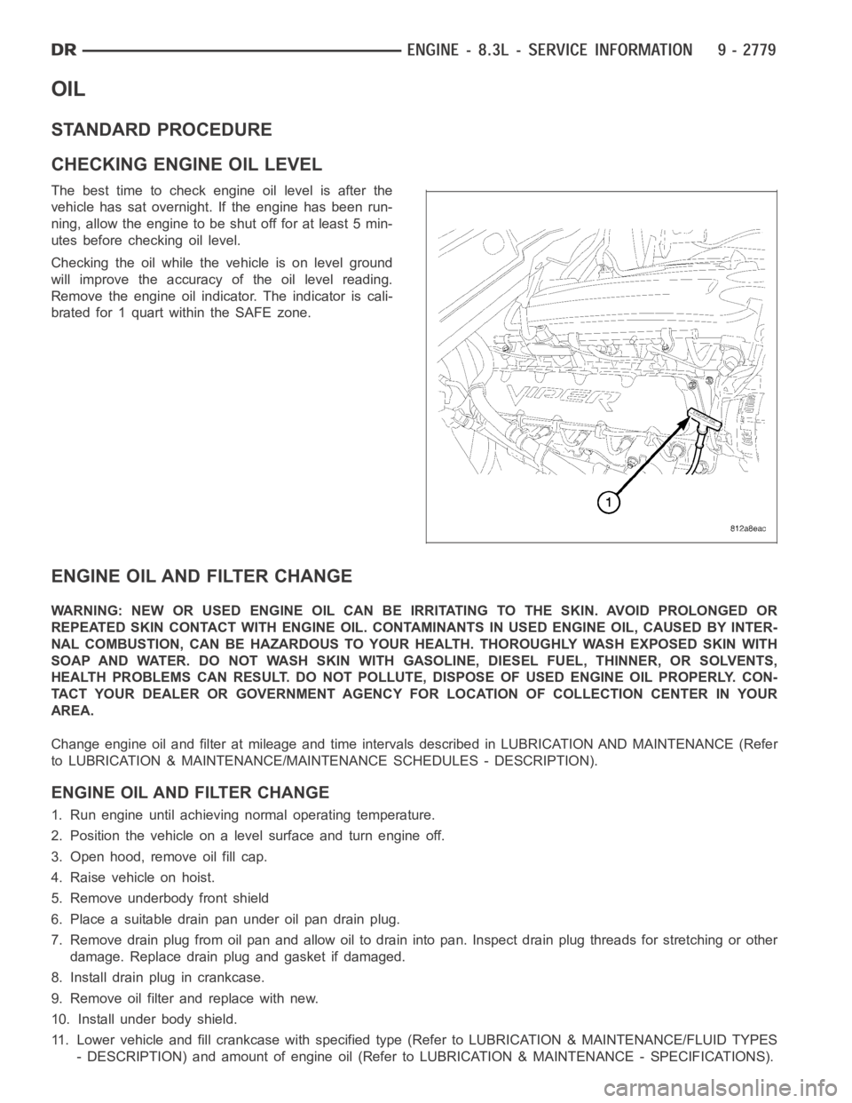
CHECKING ENGINE OIL LEVEL
The best time to check engine oil level is after the
vehicle has sat overnight. If the engine has been run-
ning, allow the engine to be shut off for at least 5 min-
utes before checking oil level.
Checking the oil while the vehicle is on level ground
will improve the accuracy of the oil level reading.
Remove the engine oil indicator. The indicator is cali-
brated for 1 quart within the SAFE zone.
ENGINE OIL AND FILTER CHANGE
WARNING: NEW OR USED ENGINE OIL CAN BE IRRITATING TO THE SKIN. AVOID PROLONGED OR
REPEATED SKIN CONTACT WITH ENGINE OIL. CONTAMINANTS IN USED ENGINE OIL, CAUSED BY INTER-
NAL COMBUSTION, CAN BE HAZARDOUS TO YOUR HEALTH. THOROUGHLY WASH EXPOSED SKIN WITH
SOAP AND WATER. DO NOT WASH SKIN WITH GASOLINE, DIESEL FUEL, THINNER, OR SOLVENTS,
HEALTH PROBLEMS CAN RESULT. DO NOT POLLUTE, DISPOSE OF USED ENGINE OIL PROPERLY. CON-
TACT YOUR DEALER OR GOVERNMENT AGENCY FOR LOCATION OF COLLECTION CENTER INYOUR
AREA.
Change engine oil and filter at mileage and time intervals described in LUBRICATION AND MAINTENANCE (Refer
to LUBRICATION & MAINTENANCE/MAINTENANCE SCHEDULES - DESCRIPTION).
ENGINE OIL AND FILTER CHANGE
1. Run engine until achieving normal operating temperature.
2. Position the vehicle on a level surface and turn engine off.
3. Open hood, remove oil fill cap.
4. Raise vehicle on hoist.
5. Remove underbody front shield
6. Place a suitable drain pan under oil pan drain plug.
7. Remove drain plug from oil pan and allow oil to drain into pan. Inspect drain plug threads for stretching or other
damage. Replace drain plug and gasket if damaged.
8. Install drain plug in crankcase.
9. Remove oil filter and replace with new.
10. Install under body shield.
11. Lower vehicle and fill crankcase with specified type (Refer to LUBRICATION & MAINTENANCE/FLUID TYPES
- DESCRIPTION) and amount of engine oil (Refer to LUBRICATION & MAINTENANCE - SPECIFICATIONS).
Page 2111 of 5267
ROD-PISTON & CONNECTING
DESCRIPTION
The pistons are made of cast aluminum with an added anodized coating on bothsides of the skirt and the top
piston ring groove for reduced wear and it’s low friction properties. Three piston rings are used; two compression
and one three-piece oil control ring. The piston pin (press-fit into the rods) joins the piston to a forged steel, frac-
tured cap, designed connecting rod, with a custom twelve point nine millimeter threaded bolt. The piston and con-
necting rod is serviced as an assembly and is not interchangeable with previous model years.
STANDARD PROCEDURE
PISTON FITTING
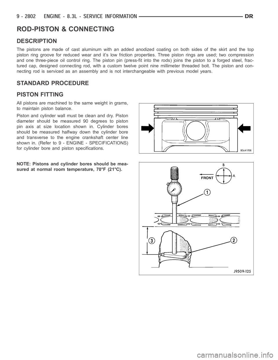
All pistons are machined to the same weight in grams,
to maintain piston balance.
Piston and cylinder wall must be clean and dry. Piston
diameter should be measured 90 degrees to piston
pin axis at size location shown in. Cylinder bores
should be measured halfway down the cylinder bore
and transverse to the engine crankshaft center line
shown in. (Refer to 9 - ENGINE - SPECIFICATIONS)
for cylinder bore and piston specifications.
NOTE: Pistons and cylinder bores should be mea-
sured at normal room temperature, 70°F (21°C).
Page 2114 of 5267
PISTON
1. Inspect all piston surfaces for nicks and scuffs.
2. Inspect piston and ring grooves for wear.
INSTALLATION
NOTE: Pistons and connecting rods are serviced
as an assembly. Left bank pistons are labeled
“ODD”. Right bank pistons are labeled “EVEN”.
1. Install piston rings (Refer to 9 - ENGINE/ENGINE
BLOCK/PISTON RINGS - INSTALLATION).
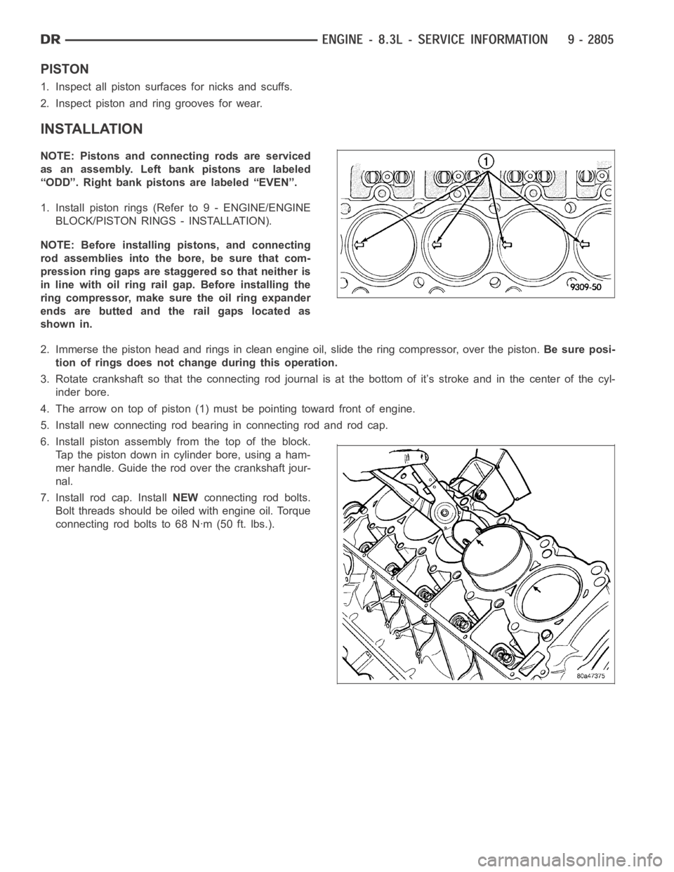
NOTE: Before installing pistons, and connecting
rod assemblies into the bore, be sure that com-
pression ring gaps are staggered so that neither is
in line with oil ring rail gap. Before installing the
ring compressor, make sure the oil ring expander
ends are butted and the rail gaps located as
shown in.
2. Immerse the piston head and rings in clean engine oil, slide the ring compressor, over the piston.Be sure posi-
tion of rings does not change during this operation.
3. Rotate crankshaft so that the connecting rod journal is at the bottom of it’s stroke and in the center of the cyl-
inder bore.
4. The arrow on top of piston (1) must be pointing toward front of engine.
5. Install new connecting rod bearing in connecting rod and rod cap.
6. Install piston assembly from the top of the block.
Tap the piston down in cylinder bore, using a ham-
mer handle. Guide the rod over the crankshaft jour-
nal.
7. Install rod cap. InstallNEWconnecting rod bolts.
Bolt threads should be oiled with engine oil. Torque
connecting rod bolts to 68 Nꞏm (50 ft. lbs.).