2006 DODGE RAM SRT-10 oil change
[x] Cancel search: oil changePage 1764 of 5267
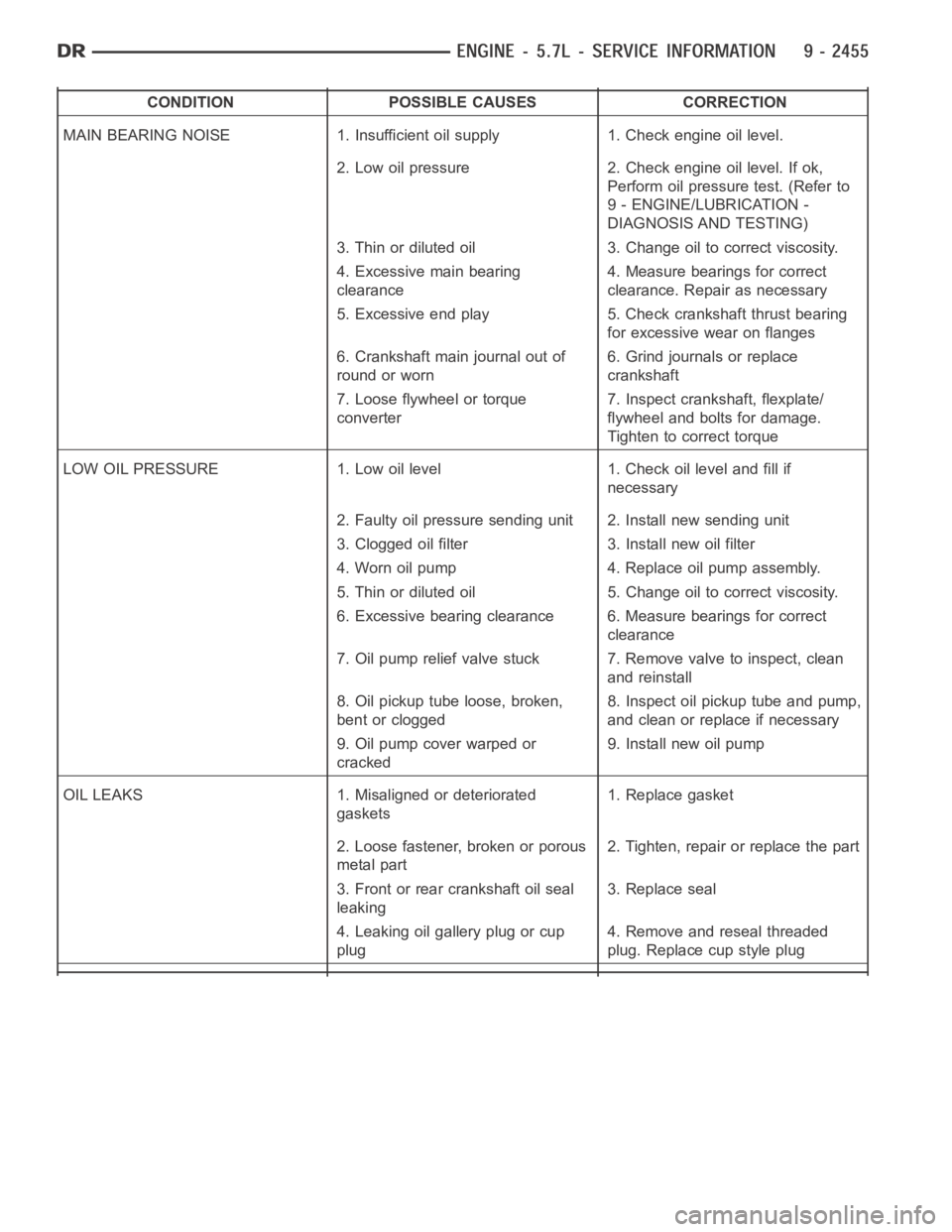
CONDITION POSSIBLE CAUSES CORRECTION
MAIN BEARING NOISE 1. Insufficient oil supply 1. Check engine oil level.
2. Low oil pressure 2. Check engine oil level. If ok,
Perform oil pressure test. (Refer to
9 - ENGINE/LUBRICATION -
DIAGNOSIS AND TESTING)
3. Thin or diluted oil 3. Change oil to correct viscosity.
4. Excessive main bearing
clearance4. Measure bearings for correct
clearance. Repair as necessary
5. Excessive end play 5. Check crankshaft thrust bearing
for excessive wear on flanges
6. Crankshaft main journal out of
round or worn6. Grind journals or replace
crankshaft
7. Loose flywheel or torque
converter7. Inspect crankshaft, flexplate/
flywheel and bolts for damage.
Tighten to correct torque
LOW OIL PRESSURE 1. Low oil level 1. Check oil level and fill if
necessary
2. Faulty oil pressure sending unit 2. Install new sending unit
3. Clogged oil filter 3. Install new oil filter
4. Worn oil pump 4. Replace oil pump assembly.
5. Thin or diluted oil 5. Change oil to correct viscosity.
6. Excessive bearing clearance 6. Measure bearings for correct
clearance
7. Oil pump relief valve stuck 7. Remove valve to inspect, clean
and reinstall
8. Oil pickup tube loose, broken,
bent or clogged8. Inspect oil pickup tube and pump,
and clean or replace if necessary
9. Oil pump cover warped or
cracked9. Install new oil pump
OIL LEAKS 1. Misaligned or deteriorated
gaskets1. Replace gasket
2. Loose fastener, broken or porous
metal part2. Tighten, repair or replace the part
3. Front or rear crankshaft oil seal
leaking3. Replace seal
4. Leaking oil gallery plug or cup
plug4. Remove and reseal threaded
plug. Replace cup style plug
Page 1856 of 5267
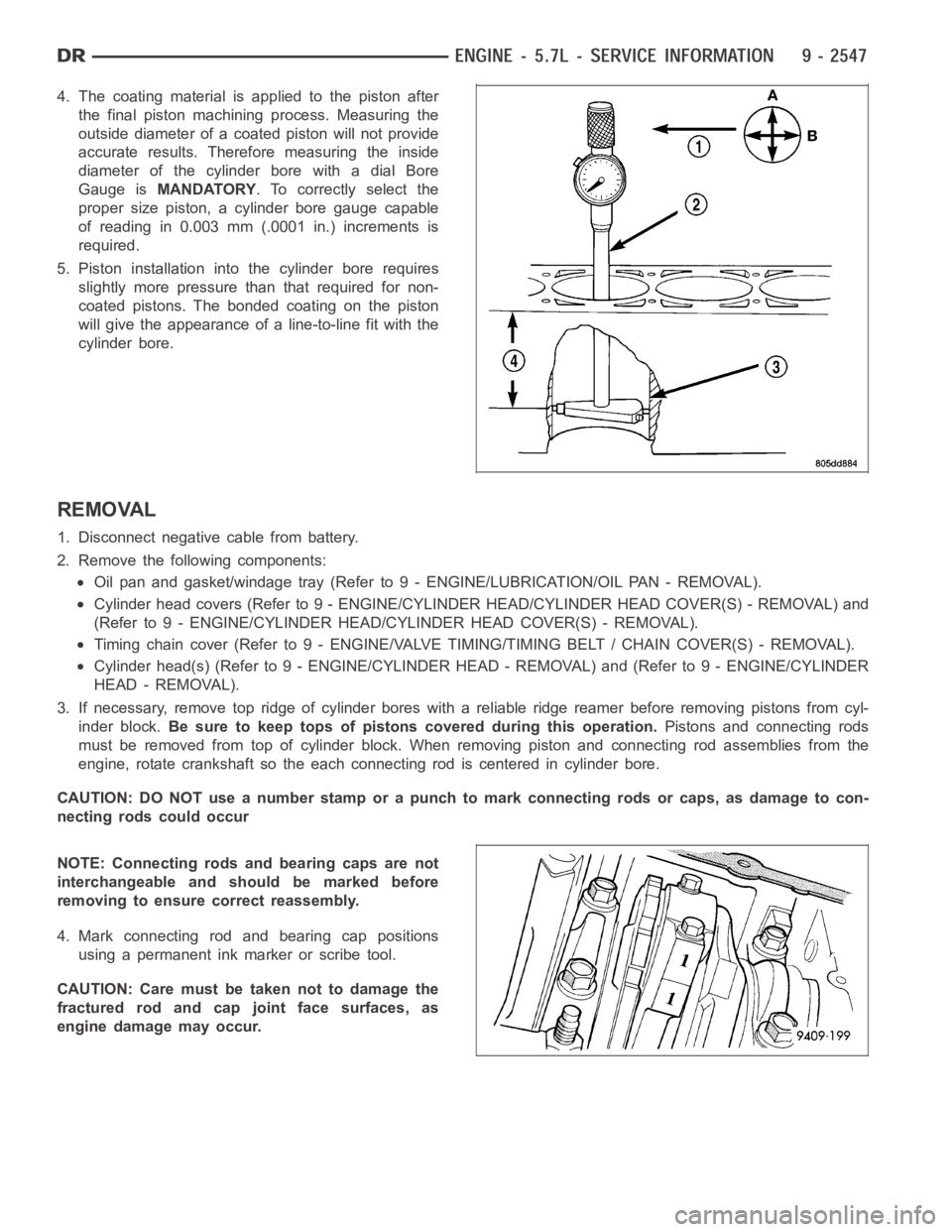
4. The coating material is applied to the piston after
the final piston machining process. Measuring the
outside diameter of a coated piston will not provide
accurate results. Therefore measuring the inside
diameter of the cylinder bore with a dial Bore
Gauge isMANDATORY. To correctly select the
proper size piston, a cylinder bore gauge capable
of reading in 0.003 mm (.0001 in.) increments is
required.
5. Piston installation intothe cylinder bore requires
slightly more pressure than that required for non-
coated pistons. The bonded coating on the piston
will give the appearance of a line-to-line fit with the
cylinder bore.
REMOVAL
1. Disconnect negative cable from battery.
2. Remove the following components:
Oil pan and gasket/windage tray (Refer to 9 - ENGINE/LUBRICATION/OIL PAN -REMOVAL).
Cylinder head covers (Refer to 9 - ENGINE/CYLINDER HEAD/CYLINDER HEAD COVER(S) - REMOVAL) and
(Refer to 9 - ENGINE/CYLINDER HEAD/CYLINDER HEAD COVER(S) - REMOVAL).
Timing chain cover (Refer to 9 - ENGINE/VALVE TIMING/TIMING BELT / CHAIN COVER(S) - REMOVAL).
Cylinder head(s) (Refer to 9 - ENGINE/CYLINDER HEAD - REMOVAL) and (Refer to 9 - ENGINE/CYLINDER
HEAD - REMOVAL).
3. If necessary, remove top ridge of cylinder bores with a reliable ridge reamer before removing pistons from cyl-
inder block.Be sure to keep tops of pistons covered during this operation.Pistons and connecting rods
must be removed from top of cylinder block. When removing piston and connecting rod assemblies from the
engine, rotate crankshaft so the each connecting rod is centered in cylinder bore.
CAUTION: DO NOT use a number stamp or a punch to mark connecting rods or caps,as damage to con-
necting rods could occur
NOTE: Connecting rods and bearing caps are not
interchangeable and should be marked before
removing to ensure correct reassembly.
4. Mark connecting rod and bearing cap positions
using a permanent ink marker or scribe tool.
CAUTION: Care must be taken not to damage the
fractured rod and cap joint face surfaces, as
engine damage may occur.
Page 1858 of 5267
INSTALLATION
1. Before installing piston and connecting rod assemblies into the bore, install the piston rings (Refer to 9 -
ENGINE/ENGINE BLOCK/PISTON RINGS - STANDARD PROCEDURE).
2. Immerse the piston head and rings in clean engine oil. Position a ring compressor over the piston and rings.
Tighten ring compressor.Ensure position of rings do not change during this operation.
3. Position bearing onto connecting rod. Lubricate bearing surface with clean engine oil.
4. Install Special Tool 8507 Connecting Rod Guides into connecting rod bolt threads.
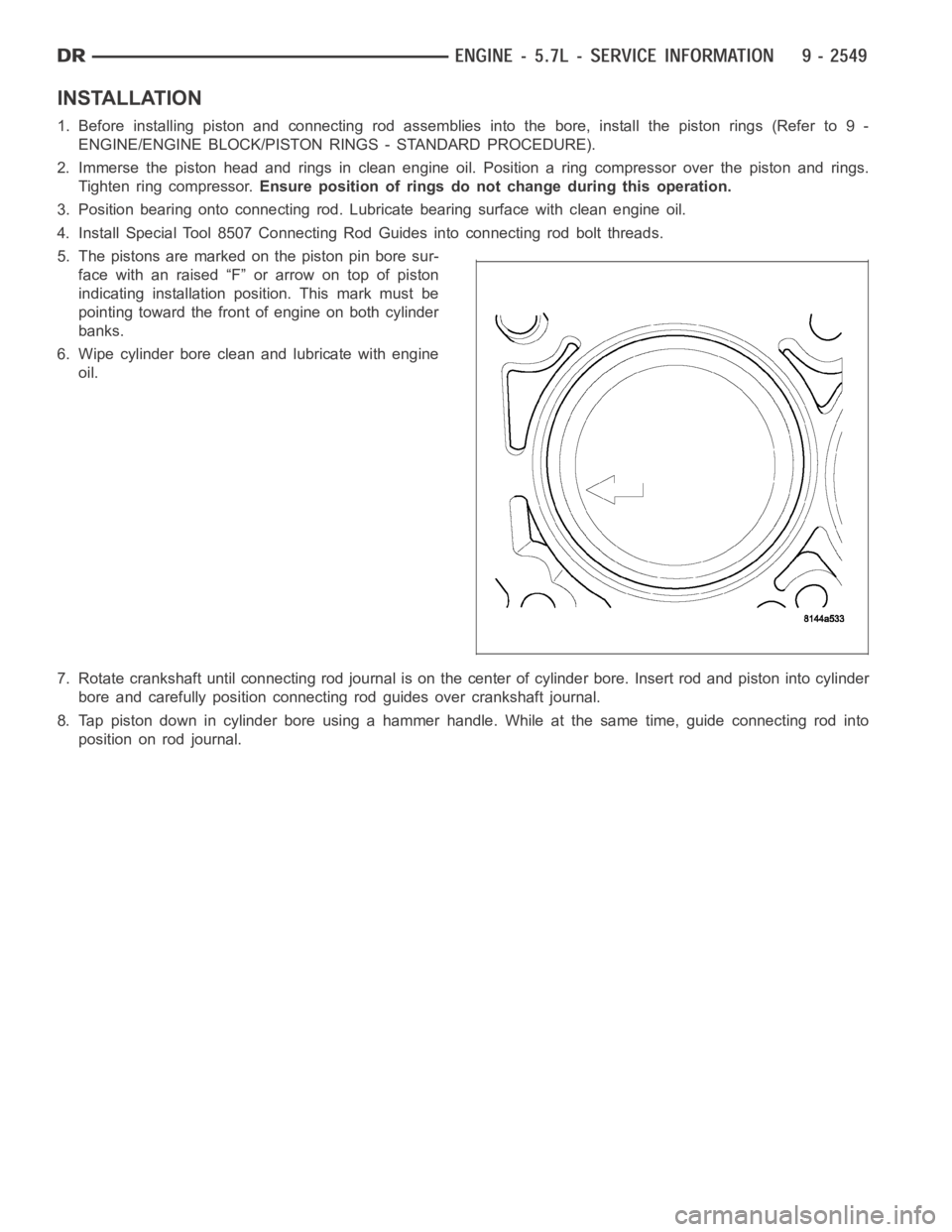
5. The pistons are marked on the piston pin bore sur-
face with an raised “F” or arrow on top of piston
indicating installation position. This mark must be
pointing toward the front of engine on both cylinder
banks.
6. Wipe cylinder bore clean and lubricate with engine
oil.
7. Rotate crankshaft until connecting rod journal is on the center of cylinder bore. Insert rod and piston into cylinder
bore and carefully position connecting rod guides over crankshaft journal.
8. Tap piston down in cylinder bore using a hammer handle. While at the same time, guide connecting rod into
position on rod journal.
Page 1877 of 5267
OIL
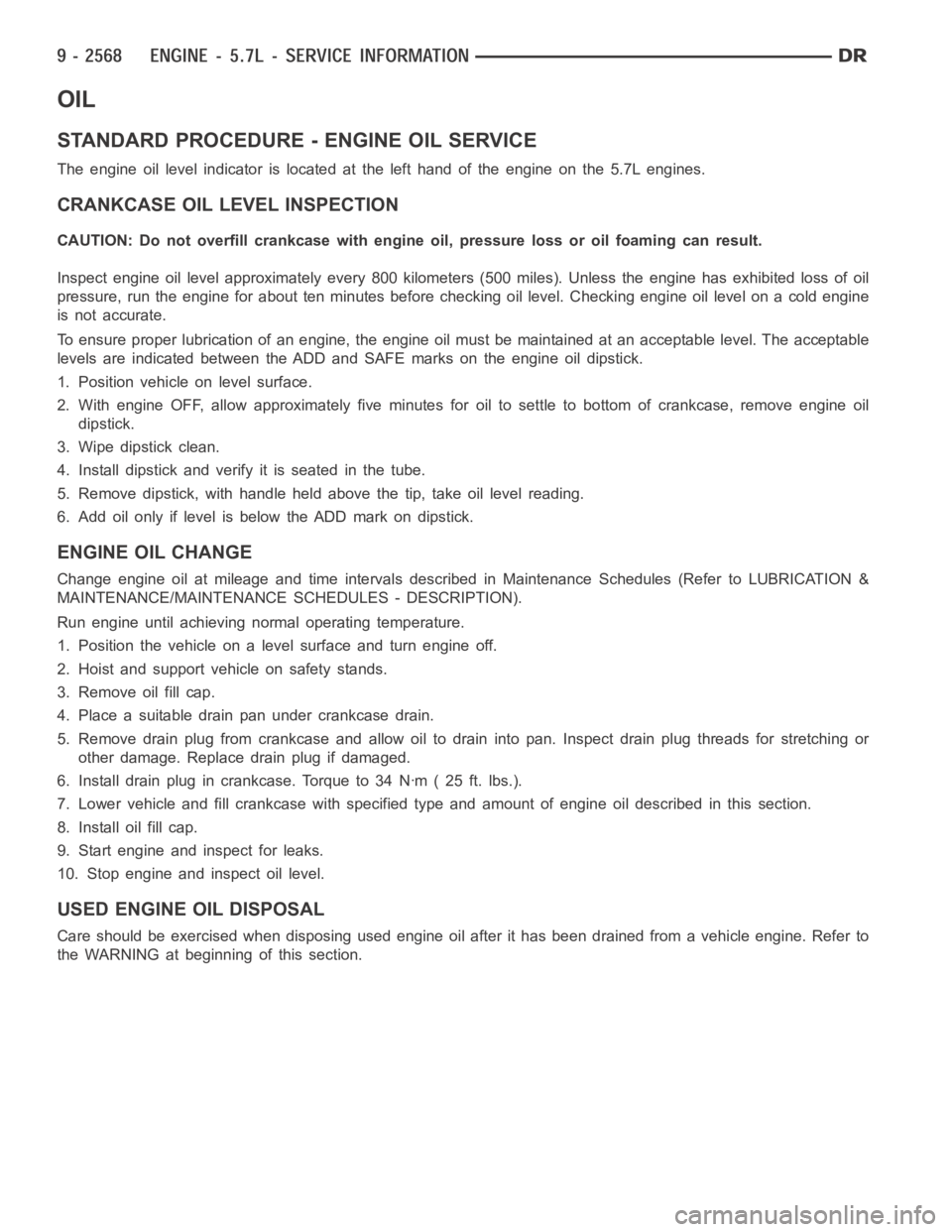
STANDARD PROCEDURE - ENGINE OIL SERVICE
The engine oil level indicator is located at the left hand of the engine on the 5.7L engines.
CRANKCASE OIL LEVEL INSPECTION
CAUTION: Do not overfill crankcase with engine oil, pressure loss or oil foaming can result.
Inspect engine oil level approximately every 800 kilometers (500 miles).Unless the engine has exhibited loss of oil
pressure, run the engine for about ten minutes before checking oil level. Checking engine oil level on a cold engine
is not accurate.
To ensure proper lubrication of an engine, the engine oil must be maintained at an acceptable level. The acceptable
levels are indicated between the ADD and SAFE marks on the engine oil dipstick.
1. Position vehicle on level surface.
2. With engine OFF, allow approximately five minutes for oil to settle to bottom of crankcase, remove engine oil
dipstick.
3. Wipe dipstick clean.
4. Install dipstick and verify it is seated in the tube.
5. Remove dipstick, with handle held above the tip, take oil level reading.
6. Add oil only if level is below the ADD mark on dipstick.
ENGINE OIL CHANGE
Change engine oil at mileage and time intervals described in Maintenance Schedules (Refer to LUBRICATION &
MAINTENANCE/MAINTENANCESCHEDULES - DESCRIPTION).
Run engine until achieving normal operating temperature.
1. Position the vehicle on a level surface and turn engine off.
2. Hoist and support vehicle on safety stands.
3. Remove oil fill cap.
4. Place a suitable drain pan under crankcase drain.
5. Remove drain plug from crankcase and allow oil to drain into pan. Inspectdrain plug threads for stretching or
other damage. Replace drain plug if damaged.
6. Install drain plug in crankcase. Torque to 34 Nꞏm ( 25 ft. lbs.).
7. Lower vehicle and fill crankcase with specified type and amount of engine oil described in this section.
8. Install oil fill cap.
9. Start engine and inspect for leaks.
10. Stop engine and inspect oil level.
USED ENGINE OIL DISPOSAL
Care should be exercised when disposing used engine oil after it has been drained from a vehicle engine. Refer to
the WARNING at beginning of this section.
Page 1907 of 5267
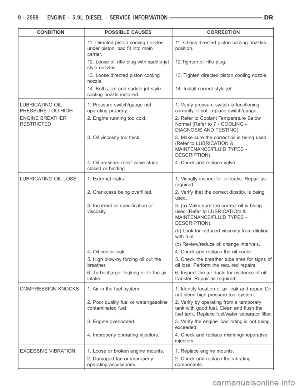
CONDITION POSSIBLE CAUSES CORRECTION
11. Directed piston cooling nozzles
under piston, bad fit into main
carrier.11. Check directed piston cooling nozzles
position.
12. Loose oil rifle plug with saddle-jet
style nozzles12.Tighten oil rifle plug.
13. Loose directed piston cooling
nozzle.13. Tighten directed piston cooling nozzle.
14. Both J-jet and saddle jet style
cooling nozzle installed.14. Install correct style jet.
LUBRICATING OIL
PRESSURE TOO HIGH1. Pressure switch/gauge not
operating properly.1. Verify pressure switch is functioning
correctly. If not, replace switch/gauge.
ENGINE BREATHER
RESTRICTED2. Engine running too cold. 2. Refer to Coolant Temperature Below
Normal (Refer to 7 - COOLING -
DIAGNOSIS AND TESTING).
3. Oil viscosity too thick. 3. Make sure the correct oil is being used.
(Refer to LUBRICATION &
MAINTENANCE/FLUID TYPES -
DESCRIPTION).
4. Oil pressure relief valve stuck
closed or binding4. Check and replace valve.
LUBRICATING OIL LOSS 1. External leaks. 1. Visually inspect for oil leaks.Repair as
required.
2. Crankcase being overfilled. 2. Verify that the correct dipstick is being
used.
3. Incorrect oil specification or
viscosity.3. (a) Make sure the correct oil is being
used (Refer to LUBRICATION &
MAINTENANCE/FLUID TYPES -
DESCRIPTION).
(b) Look for reduced viscosity from dilution
with fuel.
(c) Review/reduce oil change intervals.
4. Oil cooler leak 4. Check and replace the oil cooler.
5. High blow-by forcing oil out the
breather.5. Check the breather tube area for signs of
oil loss. Perform the required repairs.
6. Turbocharger leaking oil to the air
intake.6. Inspect the air ducts for evidence of oil
transfer. Repair as required.
COMPRESSION KNOCKS 1. Air in the fuel system. 1. Identify location of air leak and repair. Do
not bleed high pressure fuel system.
2. Poor quality fuel or water/gasoline
contaminated fuel.2. Verify by operating from a temporary
tank with good fuel. Clean and flush the
fuel tank. Replace fuel/water separator filter.
3. Engine overloaded. 3. Verify the engine load rating is not being
exceeded.
4. Improperly operating injectors. 4. Check and replace misfiring/inoperative
injectors.
EXCESSIVE VIBRATION 1. Loose or broken engine mounts. 1. Replace engine mounts.
2. Damaged fan or improperly
operating accessories.2. Check and replace the vibrating
components.
Page 1910 of 5267

EXCESSIVE WHITE SMOKE
POSSIBLE CAUSE CORRECTION
Fuel filter plugged. Refer to Powertrain Diagnostic Manual for fuel system
testing.
Fuel grade not correct or fuel quality is poor. Temporarily change fuel brands and note condition.
Change brand if necessary.
Fuel heater element or fuel heater temperature sensor
malfunctioning. This will cause wax type build-up in fuel
filter.Refer to Fuel Heater Testing (Refer to 14 - FUEL
SYSTEM/FUEL DELIVERY/FUEL HEATER -
DIAGNOSIS AND TESTING).
Fuel injector malfunctioning. A DTC should have been set. Perform “Cylinder
Performance Test
orCylinder cutout Testusing DRB
scan tool to isolate individual cylinders. Also refer to
Powertrain Diagnostic Procedures Information and,
(Refer to 14 - FUEL SYSTEM/FUEL INJECTION/FUEL
INJECTOR - DIAGNOSIS AND TESTING).
Fuel injector hold-downs loose. Torque to specifications.
Fuel injector protrusion not correct. Check washer (shim) at bottom of fuel injector for
correct thickness. (Referto 14 - FUEL SYSTEM/FUEL
INJECTION/FUEL INJECTOR - INSTALLATION)
Fuel injection pump malfunctioning. A DTC should have been set. Refer to Powertrain
Diagnostic Procedures Information.
Fuel supply side restriction. Refer to Powertrain Diagnostic Manual for fuel system
testing.
Fuel transfer (lift) pump malfunctioning. A DTC may have been set. Refer toPowertrain
Diagnostic Procedures Information.
Intake/Exhaust valve adjustments not correct (too tight). (Refer to 9 - ENGINE/CYLINDER HEAD/INTAKE/
EXHAUST VALVES & SEATS - STANDARD
PROCEDURE).
Intake manifold air temperature sensor malfunctioning. A DTC should havebeen set. Refer to Powertrain
Diagnostic Procedures Information.
Intake manifold heater circuit not functioning correctly in
cold weather.A DTC should have been set. Refer to Powertrain
Diagnostic Procedures Information. Also check heater
elements for correct operation.
Intake manifold heater elements not functioning
correctly in cold weather.A DTC should have been set if heater elements are
malfunctioning. Refer to Powertrain Diagnostic
Procedures Information.
Internal engine damage (scuffed cylinder). Analyze engine oil and inspect oil filter to locate area of
probable damage.
Restriction in fuel supply side of fuel system. Refer to Powertrain Diagnostic Manual for fuel system
testing.
EXCESSIVE BLUE SMOKE
POSSIBLE CAUSE CORRECTION
Dirty air cleaner or restricted turbocharger intake duct. Check Filter Minder
at air filter housing. (Refer to 9 -
ENGINE/AIR INTAKE SYSTEM/AIR CLEANER
ELEMENT - REMOVAL).
Air leak in boost system between turbocharger
compressor outlet and intake manifold.Service air charge system..
Obstruction in exhaust manifold. Remove exhaust manifold and inspect forblockage
(Refer to 9 - ENGINE/MANIFOLDS/EXHAUST
MANIFOLD - REMOVAL).
Page 1924 of 5267
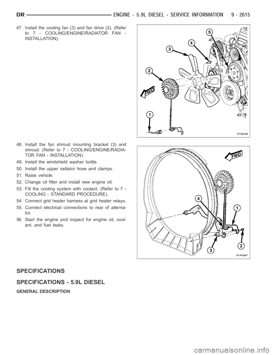
47. Install the cooling fan (3) and fan drive (2). (Refer
to 7 - COOLING/ENGINE/RADIATOR FAN -
INSTALLATION).
48. Install the fan shroud mounting bracket (3) and
shroud. (Refer to 7 - COOLING/ENGINE/RADIA-
TOR FAN - INSTALLATION).
49. Install the windshield washer bottle.
50. Install the upper radiator hose and clamps.
51. Raise vehicle.
52. Change oil filter and install new engine oil.
53. Fill the cooling system with coolant. (Refer to 7 -
COOLING - STANDARD PROCEDURE).
54. Connect grid heater harness at grid heater relays.
55. Connect electrical connections to rear of alterna-
tor.
56. Start the engine and inspect for engine oil, cool-
ant, and fuel leaks.
SPECIFICATIONS
SPECIFICATIONS - 5.9L DIESEL
GENERAL DESCRIPTION
Page 1986 of 5267
PISTON & CONNECTING ROD
DESCRIPTION
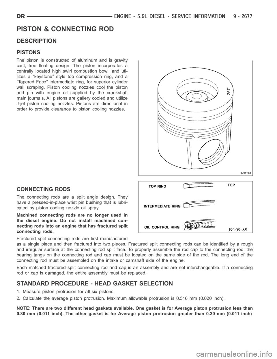
PISTONS
The piston is constructed of aluminum and is gravity
cast, free floating design. The piston incorporates a
centrally located high swirl combustion bowl, and uti-
lizes a “keystone” style top compression ring, and a
“Tapered Face” intermediate ring, for superior cylinder
wall scraping. Piston cooling nozzles cool the piston
and pin with engine oil supplied by the crankshaft
main journals. All pistons are gallery cooled and utilize
J-jet piston cooling nozzles. Pistons are directional in
order to provide clearance to piston cooling nozzles.
CONNECTING RODS
The connecting rods are a split angle design. They
have a pressed-in-place wrist pin bushing that is lubri-
cated by piston cooling nozzle oil spray.
Machined connecting rods are no longer used in
the diesel engine. Do not install machined con-
necting rods into an engine that has fractured split
connecting rods.
Fractured split connecting rods are first manufactured
asasinglepieceandthenfracturedintotwopieces.Fracturedsplitconnecting rods can be identified by a rough
and irregular surface at the connecting rod split face. To properly assemble the rod cap to the connecting rod, the
bearing tangs on the connecting rod and cap must be located on the same side of the rod. The long end of the
connecting rod must be assembled on theintake or camshaft side of the engine.
Each matched fractured split connecting rod and cap is an assembly and are not interchangeable. If a connecting
rod or cap is damaged, the entire assembly must be replaced.
STANDARD PROCEDURE - HEAD GASKET SELECTION
1. Measure piston protrusion for all six pistons.
2. Calculate the average piston protrusion. Maximum allowable protrusion is 0.516 mm (0.020 inch).
NOTE: There are two different head gaskets available. One gasket is for Average piston protrusion less than
0.30 mm (0.011 inch). The other gasket is for Average piston protrusion greater than 0.30 mm (0.011 inch)