2006 DODGE RAM SRT-10 oil change
[x] Cancel search: oil changePage 3016 of 5267
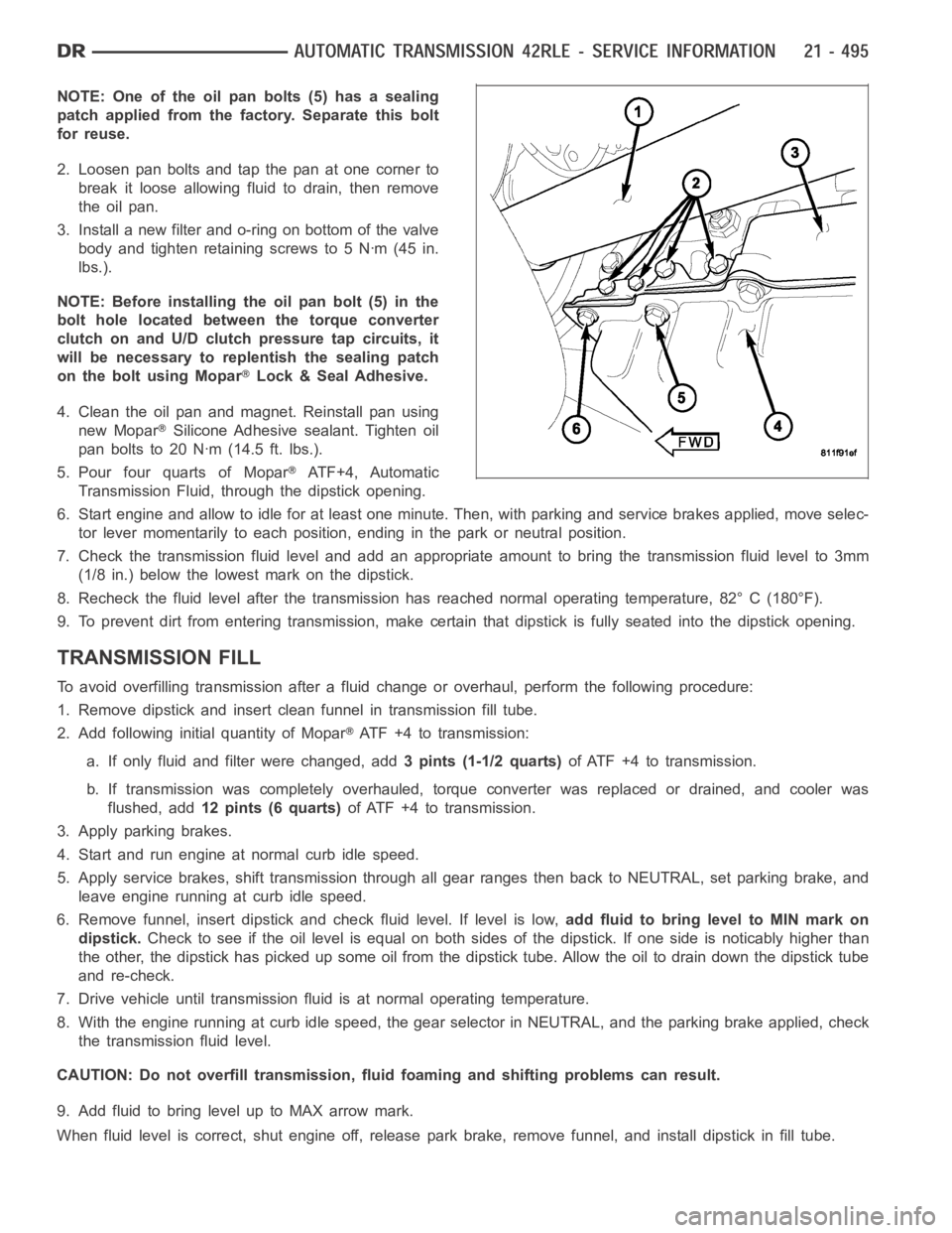
NOTE: One of the oil pan bolts (5) has a sealing
patch applied from the factory. Separate this bolt
for reuse.
2. Loosen pan bolts and tap the pan at one corner to
break it loose allowing fluid to drain, then remove
the oil pan.
3. Install a new filter and o-ring on bottom of the valve
body and tighten retaining screws to 5 Nꞏm (45 in.
lbs.).
NOTE: Before installing the oil pan bolt (5) in the
bolt hole located between the torque converter
clutch on and U/D clutch pressure tap circuits, it
will be necessary to replentish the sealing patch
on the bolt using Mopar
Lock & Seal Adhesive.
4. Clean the oil pan and magnet. Reinstall pan using
new Mopar
Silicone Adhesive sealant. Tighten oil
pan bolts to 20 Nꞏm (14.5 ft. lbs.).
5. Pour four quarts of Mopar
AT F + 4 , A u t o m a t i c
Transmission Fluid, through the dipstick opening.
6. Start engine and allow to idle for at least one minute. Then, with parkingand service brakes applied, move selec-
tor lever momentarily to each position, ending in the park or neutral position.
7. Check the transmission fluid level and add an appropriate amount to bring the transmission fluid level to 3mm
(1/8 in.) below the lowest mark on the dipstick.
8. Recheck the fluid level after the transmission has reached normal operating temperature, 82° C (180°F).
9. To prevent dirt from entering transmission, make certain that dipstickis fully seated into the dipstick opening.
TRANSMISSION FILL
To avoid overfilling transmission after a fluid change or overhaul, perform the following procedure:
1. Remove dipstick and insert clean funnel in transmission fill tube.
2. Add following initial quantity of Mopar
ATF+4totransmission:
a. If only fluid and filter were changed, add3 pints (1-1/2 quarts)of ATF +4 to transmission.
b. If transmission was completely overhauled, torque converter was replaced or drained, and cooler was
flushed, add12 pints (6 quarts)of ATF +4 to transmission.
3. Apply parking brakes.
4. Start and run engine at normal curb idle speed.
5. Apply service brakes, shift transmission through all gear ranges then back to NEUTRAL, set parking brake, and
leave engine running at curb idle speed.
6. Remove funnel, insert dipstick andcheck fluid level. If level is low,add fluid to bring level to MIN mark on
dipstick.Check to see if the oil level is equal on both sides of the dipstick. If one side is noticably higher than
the other, the dipstick has picked up some oil from the dipstick tube. Allowthe oil to drain down the dipstick tube
and re-check.
7. Drive vehicle until transmission fluid is at normal operating temperature.
8. With the engine running at curb idle speed, the gear selector in NEUTRAL,and the parking brake applied, check
the transmission fluid level.
CAUTION: Do not overfill transmission, fluid foaming and shifting problems can result.
9. Add fluid to bring level up to MAX arrow mark.
When fluid level is correct, shut engine off, release park brake, remove funnel, and install dipstick in fill tube.
Page 3069 of 5267
TORQUE CONVERTER CLUTCH (TCC)
In a standard torque converter, the impeller and tur-
bine are rotating at about the same speed and the
stator is freewheeling, providing no torque multiplica-
tion. By applying the turbine’s piston and friction mate-
rial to the front cover, a total converter engagement
can be obtained. The result of this engagement is a
direct 1:1 mechanical link between the engine and the
transmission.
The clutch can be engaged in second, third, fourth,
and fifth (if appicable) gear ranges depending on over-
drive control switch position. If the overdrive control
switch is in the normal ON position, the clutch will
engage after the shift to fourth gear. If the control
switch is in the OFF position, the clutch will engage
after the shift to third gear.
The TCM controls the torque converter by way of
internal logic software. The programming of the soft-
ware provides the TCM with control over the L/R-CC
Solenoid. There are four output logic states that can
be applied as follows:
No EMCC
Partial EMCC
Full EMCC
Gradual-to-no EMCC
NO EMCC
Under No EMCC conditions, the L/R Solenoid is OFF. There are several conditions that can result in NO EMCC
operations. No EMCC can be initiated due to a fault in the transmission or because the TCM does not see the need
for EMCC under current driving conditions.
PARTIAL EMCC
Partial EMCC operation modulates the L/R Solenoid (duty cycle) to obtain partial torque converter clutch application.
Partial EMCC operation is maintaineduntil Full EMCC is called for and actuated. During Partial EMCC some slip
does occur. Partial EMCC will usually occur at low speeds, low load and light throttle situations.
FULL EMCC
During Full EMCC operation, the TCM increases the L/R Solenoid duty cycle to full ON after Partial EMCC control
brings the engine speed within the desired slip range of transmission input speed relative to engine rpm.
GRADUAL-TO-NO EMCC
This operation is to soften the change from Full or Partial EMCC to No EMCC. This is done at mid-throttle by
decreasing the L/R Solenoid duty cycle.
REMOVAL
1. Remove transmission and torque converter from vehicle. (Refer to 21 - TRANSMISSION/AUTOMATIC - 45RFE/
545RFE - REMOVAL)
2. Place a suitable drain pan under the converter housing end of the transmission.
CAUTION: Verify that transmission is secure on the lifting device or work surface, the center of gravity of
the transmission will shift when the torque converter is removed creatingan unstable condition. The torque
converter is a heavy unit. Use caution when separating the torque converter from the transmission.
3. Pull the torque converter forward until the center hub clears the oil pumpseal.
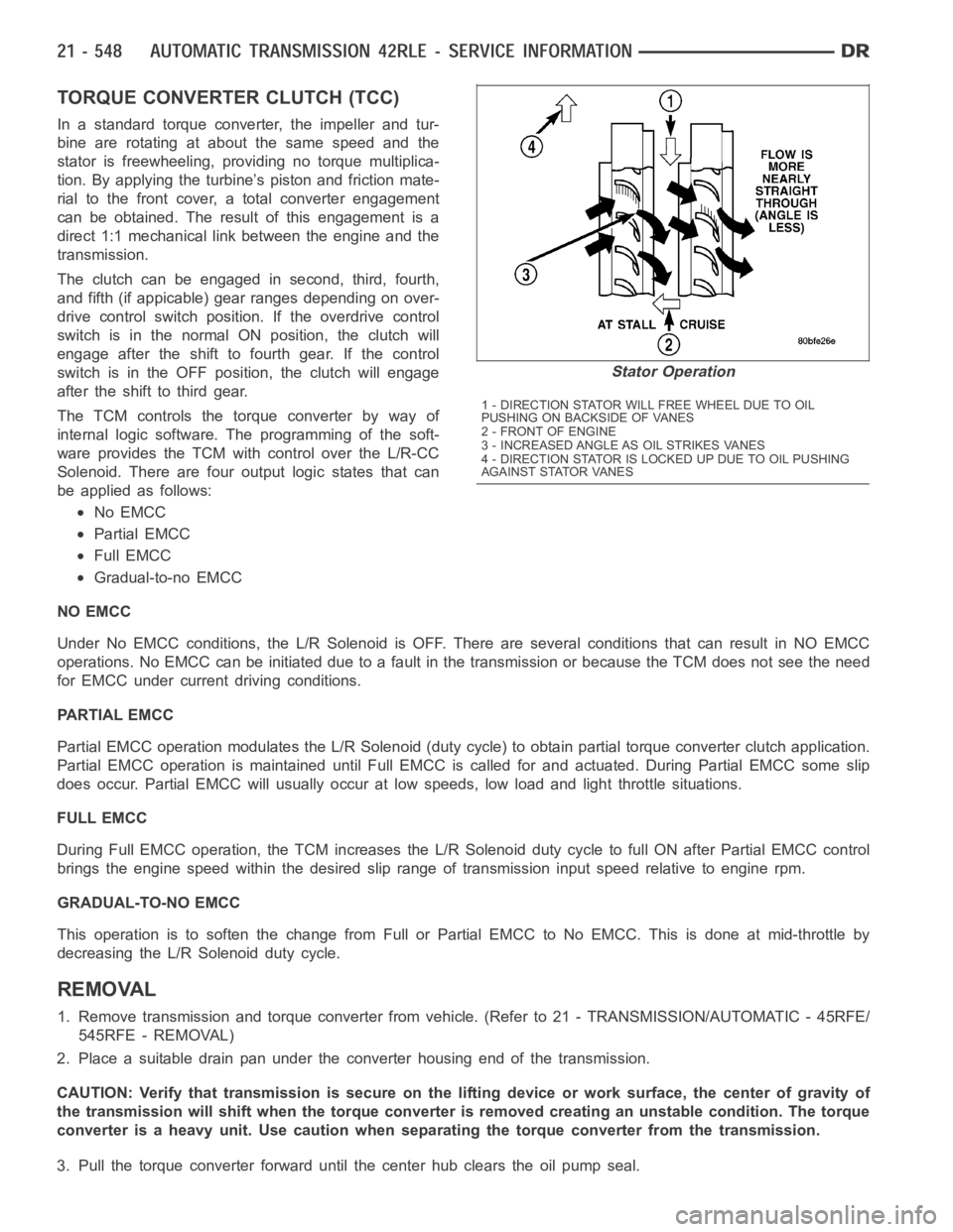
Stator Operation
1 - DIRECTION STATOR WILL FREE WHEEL DUE TO OIL
PUSHING ON BACKSIDE OF VANES
2-FRONTOFENGINE
3 - INCREASED ANGLE AS OIL STRIKES VANES
4 - DIRECTION STATOR IS LOCKED UP DUE TO OIL PUSHING
AGAINST STATOR VANES
Page 3149 of 5267
P0731-GEAR RATIO ERROR IN 1ST
For a complete wiring diagramRefer to Section 8W
When Monitored:
Continuously with the ignition on, engine running, with the transmissionin gear.
Set Condition:
If the ratio of the Input RPM to the Output RPM does not match the current gearratio. This DTC can take up
to five minutes of problem identification before illuminating the MIL
Possible Causes
CUT UD PISTON SEAL
LOW FLUID LEVEL
CRACKED OR MIS-INSTALLED PRIMARY OIL FILTER OR SEAL
STUCK OR STICKING MAIN REGULATOR VALVE
FAILED OVERRUNNING CLUTCH
CUT UD ACCUMULATOR SEAL RING
BROKEN UD ACCUMULATOR PISTON
BROKEN REACTION SHAFT SUPPORT SEAL RING
LOW LINE PRESSURE
BROKEN / MISSING MAIN VALVE BODY BLEED ORIFICE
BROKEN / MISSING DRIBBLER ORIFICE ASSEMBLY IN REACTION SHAFT SUPPORT
POOR MACHINING ON PUMP VALVE BODY FACE
INPUT SPEED SENSOR AND RELATED WIRING
TRANSMISSION SOLENOID/TRS ASSEMBLY
POWERTRAIN CONTROL MODULE
Always perform the 45RFE/545RFE Pre-Diagnostic Troubleshooting procedure before proceeding. (Refer to
21 - TRANSMISSION/TRANSAXLE/AUTOMATIC - 45RFE/545RFE - STANDARD PROCEDURE)
Theory of Operation
The transmission system uses two speed sensors, one to measure input RPM and one to measure output RPM.
These inputs are essential for proper transmission operation. Therefore, the integrity of this data is verified through
the following checks:
1) Once in a particular gear, if the gear ratio varies from the correct gear ratio, the corresponding in-gear trouble
code is set (DTCs P0731–36).
2) An excessive change in input or output speeds indicating signal intermittent may result in the DTCs P0715 and/or
P0720 being set.
3) If the common speed sensor ground circuit is lost, both sensor inputs will read the pulses from the input speed
sensor when at a stop in neutral. Since the input speed sensor reads 60 teethfrom the input clutch hub and the
output speed sensor reads 30 teeth from the park gear, the result is an apparent speed ratio of 1:2 and may cause
the DTC P1794 to set.
Page 3152 of 5267
P0732-GEAR RATIO ERROR IN 2ND
For a complete wiring diagramRefer to Section 8W
When Monitored:
Continuously with the ignition on, engine running, with the transmissionin gear.
Set Condition:
If the ratio of the Input RPM to the Output RPM does not match the current gearratio. This DTC can take up
to five minutes of problem identification before illuminating the MIL
Possible Causes
RELATED DTC’S PRESENT
INPUT SPEED SENSOR OR WIRING
LOW FLUID LEVEL
CRACKED OR MIS-INSTALLED PRIMARY OIL FILTER OR SEAL
WORN SOLENOID SWITCH VALVE OR PLUGS
STUCK OR STICKING MAIN REGULATOR VALVE
BURNED UD OR 2C CLUTCH
CUT 2C OR UD PISTON SEAL
BROKEN 2C PISTON CASTING
BROKEN OR MISSING 2C BLEED ORIFICE
BROKEN OR MISSING UD BLEED ORIFICE
CUT 2C OR UD ACCUMULATOR PISTON SEAL
CRACKED 2C OR UD ACCUMULATOR PISTON
CUT OR MISSING #5 OR #7 CHECK BALL
TRANSMISSION SOLENOID/TRS ASSEMBLY
BROKEN WELD - REACTION CARRIER TO REVERSE SUN GEAR
MISSING TEETH ON INPUT CLUTCH HUB TONE WHEEL
Always perform the 45RFE/545RFE Pre-Diagnostic Troubleshooting Procedure before proceeding. (Refer to
21 - TRANSMISSION/TRANSAXLE/AUTOMATIC - 45RFE/545RFE - STANDARD PROCEDURE)
Theory of Operation
The transmission system uses two speed sensors, one to measure input RPM and one to measure output RPM.
These inputs are essential for proper transmission operation. Therefore, the integrity of this data is verified through
the following checks:
1) Once in a particular gear, if the gear ratio varies from the correct gear ratio, the corresponding in-gear trouble
code is set (DTCs P0731-36).
2) An excessive change in input or output speeds indicating signal intermittent may result in the DTCs P0715 and/or
P0720 being set.
3) If the common speed sensor ground circuit is lost, both sensor inputs will read the pulses from the input speed
sensor when at a stop in neutral. Since the input speed sensor reads 60 teethfrom the input clutch hub and the
output speed sensor reads 30 teeth from the park gear, the result is an apparent speed ratio of 1:2 and may cause
the DTC P1794 to set.
Page 3158 of 5267
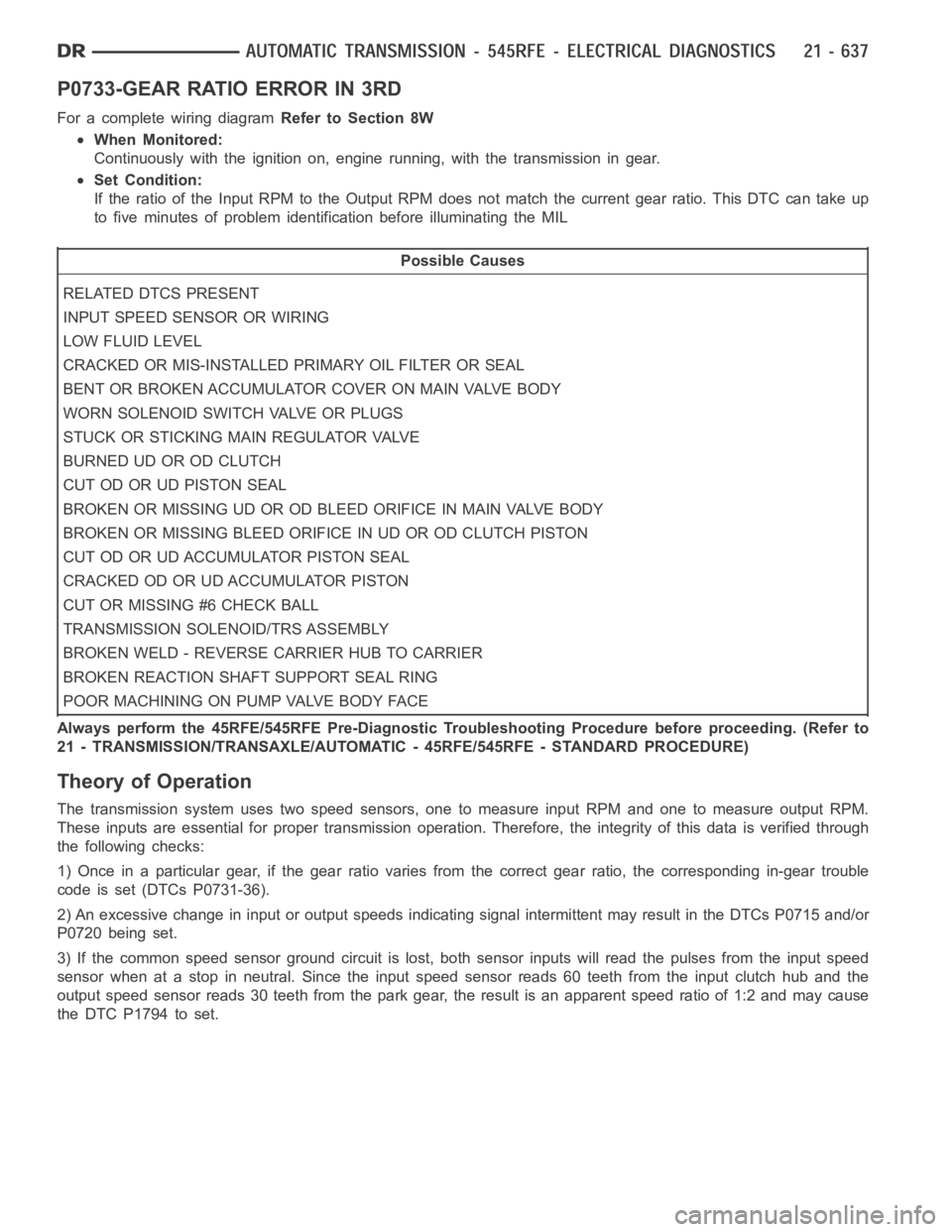
P0733-GEAR RATIO ERROR IN 3RD
For a complete wiring diagramRefer to Section 8W
When Monitored:
Continuously with the ignition on, engine running, with the transmissionin gear.
Set Condition:
If the ratio of the Input RPM to the Output RPM does not match the current gearratio. This DTC can take up
to five minutes of problem identification before illuminating the MIL
Possible Causes
RELATED DTCS PRESENT
INPUT SPEED SENSOR OR WIRING
LOW FLUID LEVEL
CRACKED OR MIS-INSTALLED PRIMARY OIL FILTER OR SEAL
BENT OR BROKEN ACCUMULATOR COVER ON MAIN VALVE BODY
WORN SOLENOID SWITCH VALVE OR PLUGS
STUCK OR STICKING MAIN REGULATOR VALVE
BURNED UD OR OD CLUTCH
CUT OD OR UD PISTON SEAL
BROKEN OR MISSING UD OR OD BLEED ORIFICE IN MAIN VALVE BODY
BROKEN OR MISSING BLEED ORIFICE IN UD OR OD CLUTCH PISTON
CUT OD OR UD ACCUMULATOR PISTON SEAL
CRACKED OD OR UD ACCUMULATOR PISTON
CUT OR MISSING #6 CHECK BALL
TRANSMISSION SOLENOID/TRS ASSEMBLY
BROKEN WELD - REVERSE CARRIER HUB TO CARRIER
BROKEN REACTION SHAFT SUPPORT SEAL RING
POOR MACHINING ON PUMP VALVE BODY FACE
Always perform the 45RFE/545RFE Pre-Diagnostic Troubleshooting Procedure before proceeding. (Refer to
21 - TRANSMISSION/TRANSAXLE/AUTOMATIC - 45RFE/545RFE - STANDARD PROCEDURE)
Theory of Operation
The transmission system uses two speed sensors, one to measure input RPM and one to measure output RPM.
These inputs are essential for proper transmission operation. Therefore, the integrity of this data is verified through
the following checks:
1) Once in a particular gear, if the gear ratio varies from the correct gear ratio, the corresponding in-gear trouble
code is set (DTCs P0731-36).
2) An excessive change in input or output speeds indicating signal intermittent may result in the DTCs P0715 and/or
P0720 being set.
3) If the common speed sensor ground circuit is lost, both sensor inputs will read the pulses from the input speed
sensor when at a stop in neutral. Since the input speed sensor reads 60 teethfrom the input clutch hub and the
output speed sensor reads 30 teeth from the park gear, the result is an apparent speed ratio of 1:2 and may cause
the DTC P1794 to set.
Page 3208 of 5267
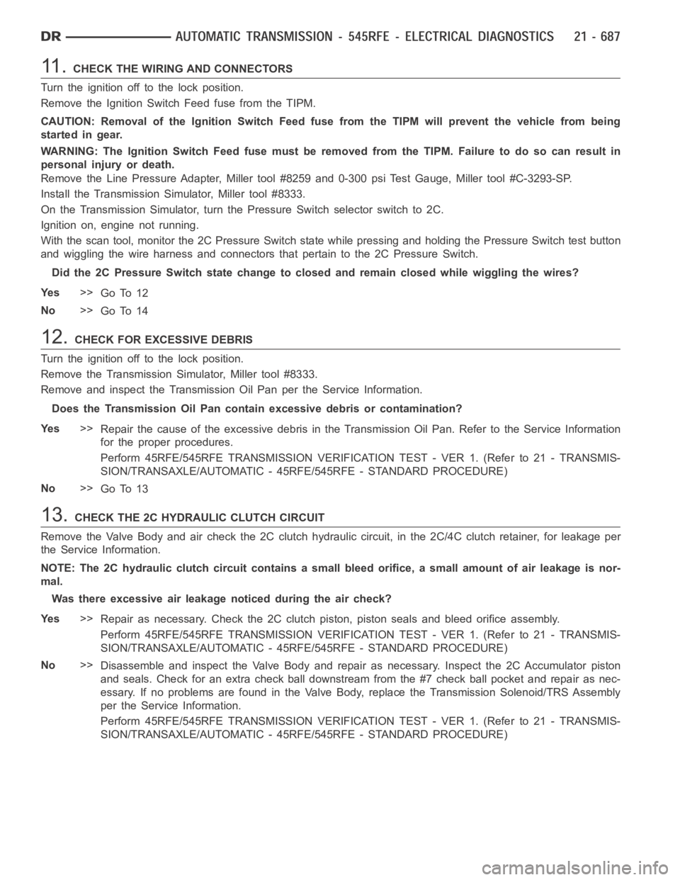
11 .CHECK THE WIRING AND CONNECTORS
Turn the ignition off to the lock position.
Remove the Ignition Switch Feed fuse from the TIPM.
CAUTION: Removal of the Ignition Switch Feed fuse from the TIPM will prevent the vehicle from being
startedingear.
WARNING: The Ignition Switch Feed fuse must be removed from the TIPM. Failure to do so can result in
personal injury or death.
Remove the Line Pressure Adapter, Miller tool #8259 and 0-300 psi Test Gauge, Miller tool #C-3293-SP.
Install the Transmission Simulator, Miller tool #8333.
On the Transmission Simulator, turn the Pressure Switch selector switch to2C.
Ignition on, engine not running.
With the scan tool, monitor the 2C Pressure Switch state while pressing andholding the Pressure Switch test button
and wiggling the wire harness and connectors that pertain to the 2C PressureSwitch.
Did the 2C Pressure Switch state change to closed and remain closed while wiggling the wires?
Ye s>>
Go To 12
No>>
Go To 14
12.CHECK FOR EXCESSIVE DEBRIS
Turn the ignition off to the lock position.
Remove the Transmission Simulator, Miller tool #8333.
Remove and inspect the Transmission Oil Pan per the Service Information.
Does the Transmission Oil Pan contain excessive debris or contamination?
Ye s>>
Repair the cause of the excessive debris in the Transmission Oil Pan. Referto the Service Information
for the proper procedures.
Perform 45RFE/545RFE TRANSMISSION VERIFICATION TEST - VER 1. (Refer to 21- TRANSMIS-
SION/TRANSAXLE/AUTOMATIC - 45RFE/545RFE - STANDARD PROCEDURE)
No>>
Go To 13
13.CHECK THE 2C HYDRAULIC CLUTCH CIRCUIT
Remove the Valve Body and air check the 2C clutch hydraulic circuit, in the 2C/4C clutch retainer, for leakage per
the Service Information.
NOTE: The 2C hydraulic clutch circuit contains a small bleed orifice, a small amount of air leakage is nor-
mal.
Was there excessive air leakage noticed during the air check?
Ye s>>
Repair as necessary. Check the 2C clutch piston, piston seals and bleed orifice assembly.
Perform 45RFE/545RFE TRANSMISSION VERIFICATION TEST - VER 1. (Refer to 21- TRANSMIS-
SION/TRANSAXLE/AUTOMATIC - 45RFE/545RFE - STANDARD PROCEDURE)
No>>
Disassemble and inspect the Valve Body and repair as necessary. Inspect the 2C Accumulator piston
and seals. Check for an extra check ball downstream from the #7 check ball pocket and repair as nec-
essary. If no problems are found in the Valve Body, replace the Transmission Solenoid/TRS Assembly
per the Service Information.
Perform 45RFE/545RFE TRANSMISSION VERIFICATION TEST - VER 1. (Refer to 21- TRANSMIS-
SION/TRANSAXLE/AUTOMATIC - 45RFE/545RFE - STANDARD PROCEDURE)
Page 3214 of 5267
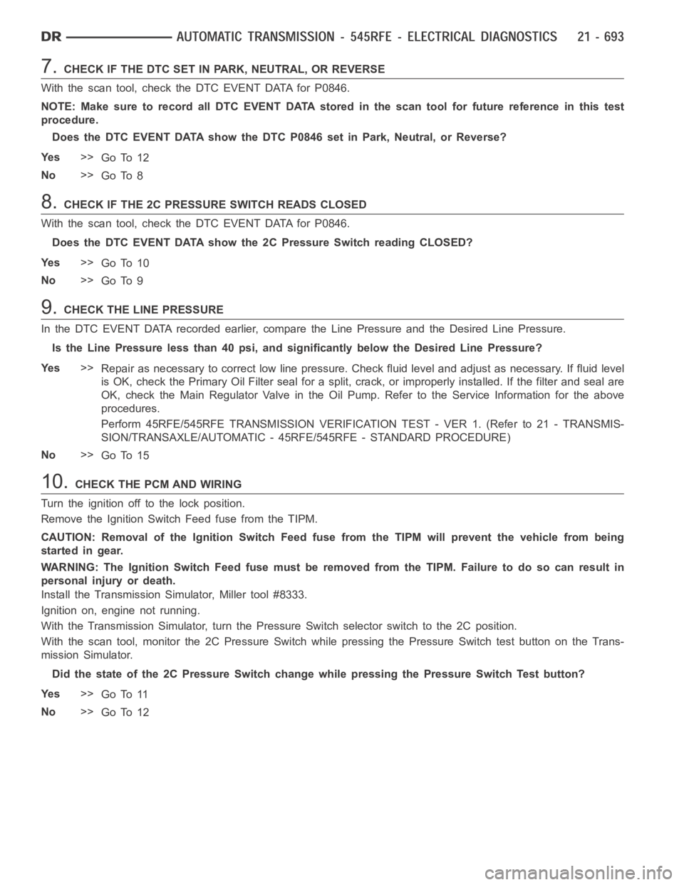
7.CHECK IF THE DTC SET IN PARK, NEUTRAL, OR REVERSE
With the scan tool, check the DTC EVENT DATA for P0846.
NOTE: Make sure to record all DTC EVENT DATA stored in the scan tool for future reference in this test
procedure.
Does the DTC EVENT DATA show the DTC P0846 set in Park, Neutral, or Reverse?
Ye s>>
Go To 12
No>>
Go To 8
8.CHECK IF THE 2C PRESSURE SWITCH READS CLOSED
With the scan tool, check the DTC EVENT DATA for P0846.
Does the DTC EVENT DATA show the 2C Pressure Switch reading CLOSED?
Ye s>>
Go To 10
No>>
Go To 9
9.CHECK THE LINE PRESSURE
In the DTC EVENT DATA recorded earlier,compare the Line Pressure and the Desired Line Pressure.
Is the Line Pressure less than 40 psi, and significantly below the Desired Line Pressure?
Ye s>>
Repair as necessary to correct low line pressure. Check fluid level and adjustasnecessary.Iffluidlevel
is OK, check the Primary Oil Filter seal for a split, crack, or improperly installed. If the filter and seal are
OK, check the Main Regulator Valve in the Oil Pump. Refer to the Service Information for the above
procedures.
Perform 45RFE/545RFE TRANSMISSION VERIFICATION TEST - VER 1. (Refer to 21- TRANSMIS-
SION/TRANSAXLE/AUTOMATIC - 45RFE/545RFE - STANDARD PROCEDURE)
No>>
Go To 15
10.CHECK THE PCM AND WIRING
Turn the ignition off to the lock position.
Remove the Ignition Switch Feed fuse from the TIPM.
CAUTION: Removal of the Ignition Switch Feed fuse from the TIPM will prevent the vehicle from being
startedingear.
WARNING: The Ignition Switch Feed fuse must be removed from the TIPM. Failure to do so can result in
personal injury or death.
Install the Transmission Simulator, Miller tool #8333.
Ignition on, engine not running.
With the Transmission Simulator, turn the Pressure Switch selector switchtothe2Cposition.
With the scan tool, monitor the 2C Pressure Switch while pressing the Pressure Switch test button on the Trans-
mission Simulator.
Did the state of the 2C Pressure Switch change while pressing the Pressure Switch Test button?
Ye s>>
Go To 11
No>>
Go To 12
Page 3226 of 5267
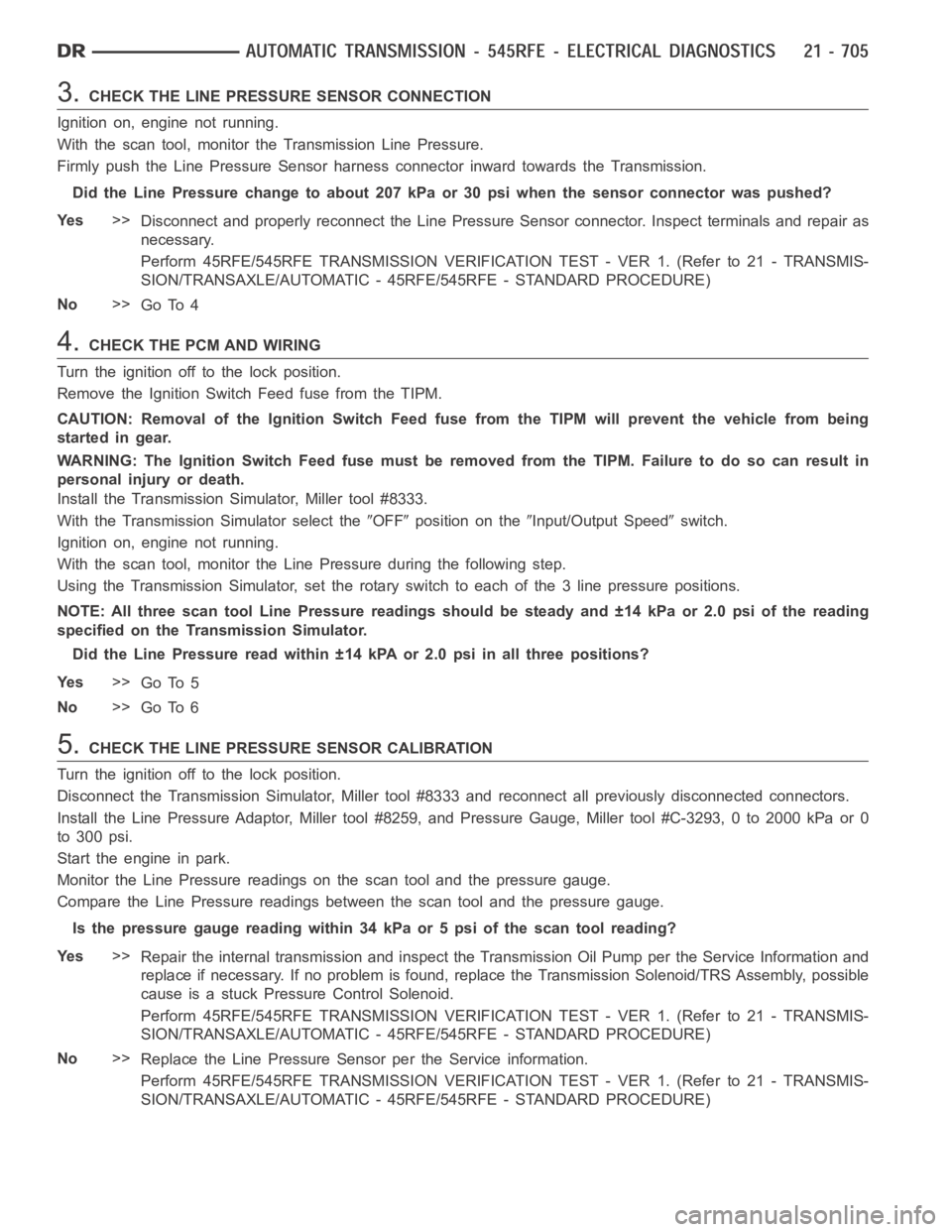
3.CHECK THE LINE PRESSURE SENSOR CONNECTION
Ignition on, engine not running.
With the scan tool, monitor the Transmission Line Pressure.
Firmly push the Line Pressure Sensor harness connector inward towards theTransmission.
Did the Line Pressure change to about 207 kPa or 30 psi when the sensor connector was pushed?
Ye s>>
Disconnect and properly reconnect the Line Pressure Sensor connector. Inspect terminals and repair as
necessary.
Perform 45RFE/545RFE TRANSMISSION VERIFICATION TEST - VER 1. (Refer to 21- TRANSMIS-
SION/TRANSAXLE/AUTOMATIC - 45RFE/545RFE - STANDARD PROCEDURE)
No>>
Go To 4
4.CHECK THE PCM AND WIRING
Turn the ignition off to the lock position.
Remove the Ignition Switch Feed fuse from the TIPM.
CAUTION: Removal of the Ignition Switch Feed fuse from the TIPM will prevent the vehicle from being
startedingear.
WARNING: The Ignition Switch Feed fuse must be removed from the TIPM. Failure to do so can result in
personal injury or death.
Install the Transmission Simulator, Miller tool #8333.
With the Transmission Simulator select the
OFFposition on theInput/Output Speedswitch.
Ignition on, engine not running.
With the scan tool, monitor the Line Pressure during the following step.
Using the Transmission Simulator, set the rotary switch to each of the 3 line pressure positions.
NOTE: All three scan tool Line Pressure readings should be steady and ±14 kPa or 2.0 psi of the reading
specified on the Transmission Simulator.
Did the Line Pressure read within ±14 kPA or 2.0 psi in all three positions?
Ye s>>
Go To 5
No>>
Go To 6
5.CHECK THE LINE PRESSURE SENSOR CALIBRATION
Turn the ignition off to the lock position.
Disconnect the Transmission Simulator, Miller tool #8333 and reconnect all previously disconnected connectors.
Install the Line Pressure Adaptor,Miller tool #8259, and Pressure Gauge,Miller tool #C-3293, 0 to 2000 kPa or 0
to 300 psi.
Start the engine in park.
Monitor the Line Pressure readings on the scan tool and the pressure gauge.
Compare the Line Pressure readings between the scan tool and the pressure gauge.
Is the pressure gauge reading within 34 kPa or 5 psi of the scan tool reading?
Ye s>>
Repair the internal transmission and inspect the Transmission Oil Pump per the Service Information and
replace if necessary. If no problem is found, replace the Transmission Solenoid/TRS Assembly, possible
cause is a stuck Pressure Control Solenoid.
Perform 45RFE/545RFE TRANSMISSION VERIFICATION TEST - VER 1. (Refer to 21- TRANSMIS-
SION/TRANSAXLE/AUTOMATIC - 45RFE/545RFE - STANDARD PROCEDURE)
No>>
Replace the Line Pressure Sensor per the Service information.
Perform 45RFE/545RFE TRANSMISSION VERIFICATION TEST - VER 1. (Refer to 21- TRANSMIS-
SION/TRANSAXLE/AUTOMATIC - 45RFE/545RFE - STANDARD PROCEDURE)