2006 DODGE RAM SRT-10 oil change
[x] Cancel search: oil changePage 3502 of 5267
INSPECTION
Inspect all of the valve body mating surfaces for scratches, nicks, burrs,or distortion. Use a straightedge to check
surface flatness. Minor scratches may be removed with crocus cloth using only very light pressure.
Minor distortion of a valve body mating surface may be corrected by smoothing the surface with a sheet of crocus
cloth. Position the crocus cloth on a surface plate, sheet of plate glass orequally flat surface. If distortion is severe
or any surfaces are heavily scored, the valve body will have to be replaced.
Inspect the valves and plugs for scratches, burrs, nicks, or scores. Minorsurface scratches on steel valves and
plugs can be removed with crocus cloth butdo not round off the edges of the valve or plug lands.Maintaining
sharpness of these edges is vitally important. The edges prevent foreign matter from lodging between the valves
and plugs and the bore.
Inspect all the valve and plug bores in the valve body. Use a penlight to viewthe bore interiors. Replace the valve
body if any bores are distorted or scored. Inspect all of the valve body springs. The springs must be free of dis-
tortion, warpage or broken coils.
Trial fit each valve and plug in its bore to check freedom of operation. Whenclean and dry, the valves and plugs
shoulddropfreelyintothebores.
Valve body bores do not change dimensionally with use. If the valve body functioned correctly when new, it will
continue to operate properly after cleaning and inspection. It should notbe necessary to replace a valve body
assembly unless it is damaged in handling.
Inspect all the accumulator bores in the valve body. Use a penlight to view the bore interiors. Replace the valve
body if any bores are distorted or scored. Inspect all of the accumulator springs. The springs must be free of dis-
tortion, warpage or broken coils.
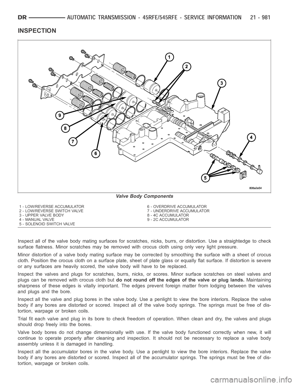
Valve Body Components
1 - LOW/REVERSE ACCUMULATOR 6 - OVERDRIVE ACCUMULATOR
2 - LOW/REVERSE SWITCH VALVE 7 - UNDERDRIVE ACCUMULATOR
3 - UPPER VALVE BODY 8 - 4C ACCUMULATOR
4 - MANUAL VALVE 9 - 2C ACCUMULATOR
5 - SOLENOID SWITCH VALVE
Page 3801 of 5267
5. Line pressure should be 54-60 psi (372-414 kPa) with throttle lever forward and gradually increase to 90-96 psi
(621-662 kPa) as lever is moved rearward.
Test Three - Transmission In D Range Third Gear
This test checks pressure regulation and condition of the clutch circuits. Both test gauges are required for this test.
1. Turn OD switch off.
2. Leave vehicle on hoist and leave Oil Pressure Gauge C-3292 in place at accumulator port.
3. Move Oil Pressure Gauge C-3293-SP over to front servo port for this test.
4. Have helper start and run engine at 1600 rpm for this test.
5. Move transmission shift lever two detents rearward from full forward position. This is D range.
6. Read pressures on both gauges as transmission throttle lever is gradually moved from full forward to full rear-
ward position:
Line pressure at accumulator in D range third gear, should be 54-60 psi (372-414 kPa) with throttle lever for-
ward and increase as lever is moved rearward.
Front servo pressure in D range third gear, should be within 3 psi (21 kPa) ofline pressure up to kickdown
point.
Test Four - Transmission In Reverse
This test checks pump output, pressure regulation and the front clutch andrear servo circuits. Use 300 psi Oil
Pressure Gauge C-3293-SP for this test.
1. Leave vehicle on hoist and leave Oil Pressure Gauge C-3292 in place at accumulator port.
2. Move 300 psi Oil Pressure Gauge C-3293-SP back to rear servo port.
3. Have helper start and run engine at 1600 rpm for test.
4. Move transmission shift lever four detents rearward from full forward position. This is Reverse range.
5. Move transmission throttle lever fully forward then fully rearward andnote reading at Gauge C-3293-SP.
6. Pressure should be 145 - 175 psi (1000-1207 kPa) with throttle lever forward and increase to 230 - 280 psi
(1586-1931 kPa) as lever is gradually moved rearward.
Test Five - Governor Pressure
This test checks governor operation by measuring governor pressure response to changes in vehicle speed. It is
usually not necessary to check governor operation unless shift speeds areincorrect or if the transmission will not
downshift. The test should be performed on the road or on a hoist that will allow the rear wheels to rotate freely.
1. Move 100 psi Oil Pressure Gauge C-3292 to governor pressure port.
2. Move transmission shift lever two detents rearward from full forward position. This is D range.
3. Have helper start and run engine at curb idle speed. Then firmly apply service brakes so wheels will not rotate.
4. Note governor pressure:
Governor pressure should be no more than 20.6 kPa (3 psi) at curb idle speed and wheels not rotating.
If pressure exceeds 20.6 kPa (3 psi), a fault exists in governor pressure control system.
5. Release brakes, slowly increase engine speed, and observe speedometerand pressure test gauge (do not
exceed 30 mph on speedometer). Governor pressure should increase in proportion to vehicle speed. Or approx-
imately 6.89 kPa (1 psi) for every 1 mph.
6. Governor pressure rise should be smooth and drop back to no more than 20.6kPa (3 psi), after engine returns
to curb idle and brakes are applied to prevent wheels from rotating.
7. Compare results of pressure test with analysis chart.
Test Six - Transmission In Overdrive Fourth Gear
This test checks line pressure at the overdrive clutch in fourth gear range. Use 300 psi Oil Pressure Gauge
C-3293-SP for this test. The test should be performed on the road or on a chassis dyno.
1. Remove tachometer; it is not needed for this test.
2. Move 300 psi Oil Pressure Gauge to overdrive clutch pressure test port. Then remove other gauge and reinstall
test port plug.
Page 3805 of 5267
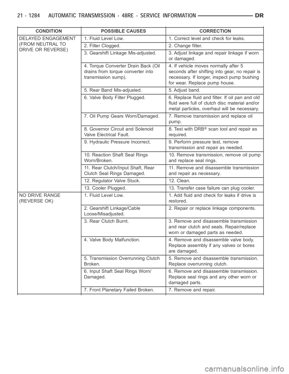
CONDITION POSSIBLE CAUSES CORRECTION
DELAYED ENGAGEMENT
(FROM NEUTRAL TO
DRIVE OR REVERSE)1. Fluid Level Low. 1. Correct level and check for leaks.
2. Filter Clogged. 2. Change filter.
3. Gearshift Linkage Mis-adjusted. 3. Adjust linkage and repair linkage ifworn
or damaged.
4. Torque Converter Drain Back (Oil
drains from torque converter into
transmission sump).4. If vehicle moves normally after 5
seconds after shifting into gear, no repair is
necessary. If longer, inspect pump bushing
for wear. Replace pump house.
5. Rear Band Mis-adjusted. 5. Adjust band.
6. Valve Body Filter Plugged. 6. Replace fluid and filter. If oil pan and old
fluid were full of clutch disc material and/or
metal particles, overhaul will be necessary.
7. Oil Pump Gears Worn/Damaged. 7. Remove transmission and replace oil
pump.
8. Governor Circuit and Solenoid
Valve Electrical Fault.8. Test with DRB
scan tool and repair as
required.
9. Hydraulic Pressure Incorrect. 9. Perform pressure test, remove
transmission and repair as needed.
10. Reaction Shaft Seal Rings
Worn/Broken.10. Remove transmission, remove oil pump
and replace seal rings.
11. Rear Clutch/Input Shaft, Rear
Clutch Seal Rings Damaged.11. Remove and disassemble transmission
and repair as necessary.
12. Regulator Valve Stuck. 12. Clean.
13. Cooler Plugged. 13. Transfer case failure can plug cooler.
NO DRIVE RANGE
(REVERSE OK)1. Fluid Level Low. 1. Add fluid and check for leaks if drive is
restored.
2. Gearshift Linkage/Cable
Loose/Misadjusted.2. Repair or replace linkage components.
3. Rear Clutch Burnt. 3. Removeand disassemble transmission
and rear clutch and seals. Repair/replace
worn or damaged parts as needed.
4. Valve Body Malfunction. 4. Remove and disassemble valve body.
Replace assembly if any valves or bores
are damaged.
5. Transmission Overrunning Clutch
Broken.5. Remove and disassemble transmission.
Replace overrunning clutch.
6. Input Shaft Seal Rings Worn/
Damaged.6. Remove and disassemble transmission.
Replace seal rings and any other worn or
damaged parts.
7. Front Planetary Failed Broken. 7. Remove and repair.
Page 3858 of 5267
Component Metric Inch
Overdrive piston thrust plate Thrust plate and
spacer are select fit.
Refer to size charts
and selection
procedures in
Overdrive Unit D&A
procedures Intermediateshaft spacer
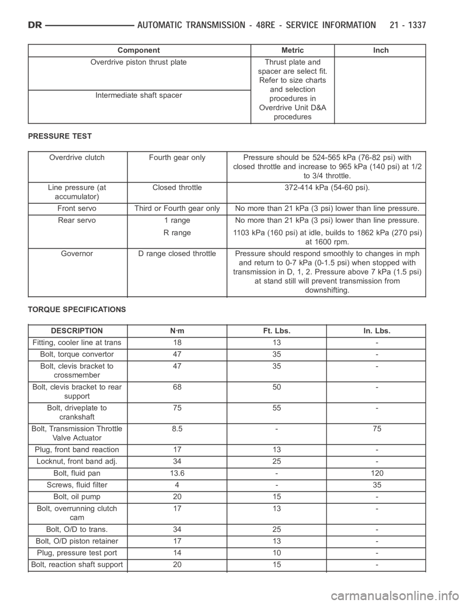
PRESSURE TEST
Overdrive clutch Fourth gear only Pressure should be 524-565 kPa (76-82 psi) with
closed throttle and increase to 965 kPa (140 psi) at 1/2
to 3/4 throttle.
Line pressure (at
accumulator)Closed throttle 372-414 kPa (54-60 psi).
Front servo Third or Fourth gear only No more than 21 kPa (3 psi) lower than line pressure.
Rearservo 1range Nomorethan21kPa(3psi)lowerthanlinepressure.
R range 1103 kPa (160 psi) at idle, builds to 1862 kPa (270 psi)
at 1600 rpm.
Governor D range closed throttle Pressure should respond smoothly to changes in mph
andreturnto0-7kPa(0-1.5psi)whenstoppedwith
transmission in D, 1, 2. Pressure above 7 kPa (1.5 psi)
at stand still will prevent transmission from
downshifting.
TORQUE SPECIFICATIONS
DESCRIPTION Nꞏm Ft. Lbs. In. Lbs.
Fitting, cooler line at trans 18 13 -
Bolt, torque convertor 47 35 -
Bolt, clevis bracket to
crossmember47 35 -
Bolt, clevis bracket to rear
support68 50 -
Bolt, driveplate to
crankshaft75 55 -
Bolt, Transmission Throttle
Va l v e A c t u a t o r8.5 - 75
Plug, front band reaction 17 13 -
Locknut, front band adj. 34 25 -
Bolt, fluid pan 13.6 - 120
Screws, fluid filter 4 - 35
Bolt, oil pump 20 15 -
Bolt, overrunning clutch
cam17 13 -
Bolt, O/D to trans. 34 25 -
Bolt, O/D piston retainer 17 13 -
Plug, pressure test port 14 10 -
Bolt, reaction shaft support 20 15 -
Page 3869 of 5267
OPERATION
Compensation is required for performance variations of two of the input devices. Though the slope of the transfer
functions is tightly controlled, offset may vary due to various environmental factors or manufacturing tolerances.
The pressure transducer is affected by barometric pressure as well as temperature. Calibration of the zero pressure
offset is required to compensate for shifting output due to these factors.
Normal calibration will be performed when sump temperature is above 50 degrees F, or in the absence of sump
temperature data, after the first 10 minutes of vehicle operation. Calibration of the pressure transducer offset occurs
each time the output shaft speed falls below 200 RPM. Calibration shall be repeated each 3 seconds the output
shaft speed is below 200 RPM. A 0.5 second pulse of 95% duty cycle is applied to the governor pressure solenoid
valve and the transducer output is read during this pulse. Averaging of thetransducer signal isnecessary to reject
electrical noise.
Under cold conditions (below 50 degrees F sump), the governor pressure solenoid valve response may be too slow
to guarantee 0 psi during the 0.5 second calibration pulse. Calibration pulses are continued during this period, how-
ever the transducer output valves are discarded. Transducer offset must be read at key-on, under conditions which
promote a stable reading. This value is retained and becomes the offset during the
coldperiod of operation.
GOVERNOR PRESSURE SOLENOID VALVE
The inlet side of the solenoid valve is exposed to normal transmission linepressure. The outlet side of the valve
leads to the valve body governor circuit.
The solenoid valve regulates line pressure to produce governor pressure.Theaveragecurrentsuppliedtothesole-
noid controls governor pressure. One amp current produces zero kPa/psi governor pressure. Zero amps sets the
maximum governor pressure.
The powertrain control module (PCM) turns on the trans control relay whichsupplies electrical power to the solenoid
valve. Operating voltage is 12 volts (DC). The PCM controls the ground sideof the solenoid using the governor
pressure solenoidcontrol circuit.
GOVERNOR PRESSURE SENSOR
The sensor output signal provides the necessary feedback to the PCM. This feedback is needed to adequately
control governor pressure.
GOVERNOR BODY AND TRANSFER PLATE
The transfer plate channels line pressure to the solenoid valve through the governor body. It also channels governor
pressure from the solenoid valve to the governor circuit. It is the solenoid valve that develops the necessary gov-
ernor pressure.
GOVERNOR PRESSURE CURVES
LOW TRANSMISSION FLUID TEMPERATURE
When the transmission fluid is cold the conventional governor can delay shifts, resulting in higher than normal shift
speeds and harsh shifts. The electronically controlled low temperature governor pressure curve is higher than nor-
mal to make the transmission shift at normal speeds and sooner. The PCM usesa temperature sensor in the trans-
mission oil sump to determine when low temperature governor pressure is needed.
NORMAL OPERATION
Normal operation is refined through the increased computing power of the PCM and through access to data on
engine operating conditions provided by the PCM that were not available with the previous stand-alone electronic
module. This facilitated the development of a load adaptive shift strategy - the ability to alter the shift schedule in
response to vehicle load condition. One manifestation of this capabilityis grade
huntingprevention - the ability of
the transmission logic to delay an upshift on a grade if the engine does not have sufficient power to maintain speed
in the higher gear. The 3-2 downshift and the potential for hunting betweengears occurs with a heavily loaded
vehicle or on steep grades. When hunting occurs, it is very objectionable because shifts are frequent and accom-
panied by large changes in noise and acceleration.
Page 3876 of 5267

PROCEDURE TWO
1. Start engine and apply parking brake.
2. Shift the transmission into DRIVE for approximately 2 seconds.
3. Shift the transmission into REVERSE for approximately 2 seconds.
4. Shift the transmission into PARK.
5. Hook up DRB
scan tool and select engine.
6. Select sensors.
7. Read the transmission temperature value.
8. Compare the fluid temperature value with the chart.
9. Adjust transmission fluid level shown on the dipstick according to the chart.
NOTE: After adding any fluid to the transmission, wait a minimum of 2 minutes for the oil to fully drain from
the fill tube into the transmission before rechecking the fluid level.
10. Check transmission for leaks.
FLUID AND FILTER REPLACEMENT
For proper service intervals (Refer to LUBRICATION & MAINTENANCE/MAINTENANCE SCHEDULES - DESCRIP-
TION). The service fluid fill after a filter change is approximately 3.8 liters (4.0 quarts).
Page 3878 of 5267
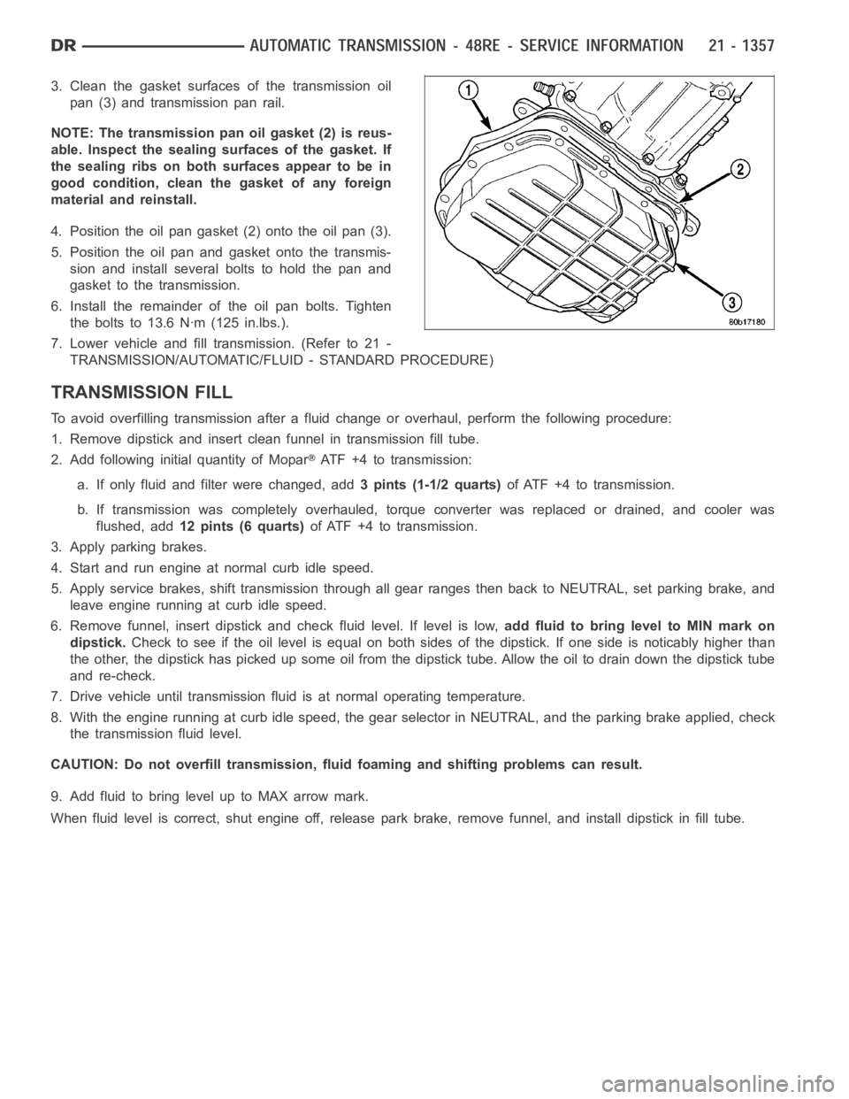
3. Clean the gasket surfaces of the transmission oil
pan (3) and transmission pan rail.
NOTE: The transmission pan oil gasket (2) is reus-
able. Inspect the sealing surfaces of the gasket. If
the sealing ribs on both surfaces appear to be in
good condition, clean the gasket of any foreign
material and reinstall.
4. Position the oil pan gasket (2) onto the oil pan (3).
5. Position the oil pan and gasket onto the transmis-
sion and install several bolts to hold the pan and
gasket to the transmission.
6. Install the remainder of the oil pan bolts. Tighten
the bolts to 13.6 Nꞏm (125 in.lbs.).
7. Lower vehicle and fill transmission. (Refer to 21 -
TRANSMISSION/AUTOMATIC/FLUID - STANDARD PROCEDURE)
TRANSMISSION FILL
To avoid overfilling transmission after a fluid change or overhaul, perform the following procedure:
1. Remove dipstick and insert clean funnel in transmission fill tube.
2. Add following initial quantity of Mopar
ATF+4totransmission:
a. If only fluid and filter were changed, add3 pints (1-1/2 quarts)of ATF +4 to transmission.
b. If transmission was completely overhauled, torque converter was replaced or drained, and cooler was
flushed, add12 pints (6 quarts)of ATF +4 to transmission.
3. Apply parking brakes.
4. Start and run engine at normal curb idle speed.
5. Apply service brakes, shift transmission through all gear ranges then back to NEUTRAL, set parking brake, and
leave engine running at curb idle speed.
6. Remove funnel, insert dipstick andcheck fluid level. If level is low,add fluid to bring level to MIN mark on
dipstick.Check to see if the oil level is equal on both sides of the dipstick. If one side is noticably higher than
the other, the dipstick has picked up some oil from the dipstick tube. Allowthe oil to drain down the dipstick tube
and re-check.
7. Drive vehicle until transmission fluid is at normal operating temperature.
8. With the engine running at curb idle speed, the gear selector in NEUTRAL,and the parking brake applied, check
the transmission fluid level.
CAUTION: Do not overfill transmission, fluid foaming and shifting problems can result.
9. Add fluid to bring level up to MAX arrow mark.
When fluid level is correct, shut engine off, release park brake, remove funnel, and install dipstick in fill tube.
Page 4007 of 5267
sharpness of these edges is vitally important. The edges prevent foreign matter from lodging between the valves
and plugs and the bore.
Inspect all the valve and plug bores in the valve body. Use a penlight to viewthe bore interiors. Replace the valve
body if any bores are distorted or scored. Inspect all of the valve body springs. The springs must be free of dis-
tortion, warpage or broken coils.
Check the two separator plates for distortion or damage of any kind. Inspect the upper housing, lower housing, 3-4
accumulator housing, and transfer plate carefully. Be sure all fluid passages are clean and clear. Check condition of
the upper housing and transfer plate check balls as well. The check balls and ball seats must not be worn or dam-
aged.
Trial fit each valve and plug in its bore to check freedom of operation. Whenclean and dry, the valves and plugs
shoulddropfreelyintothebores.
Valve body bores do not change dimensionally with use. If the valve body functioned correctly when new, it will
continue to operate properly after cleaning and inspection. It should notbe necessary to replace a valve body
assembly unless it is damaged in handling.
The only serviceable valve body components are listed below. The remaining valve body components are serviced
only as part of a complete valve body assembly. Serviceable parts are:
dual solenoid and harness assembly
solenoid gasket
solenoid case connector O-rings and shoulder bolt
switch valve and spring
pressure adjusting screw and bracket assembly
throttle lever
manual lever and shaft seal
throttle lever shaft seal, washer, and E-clip
fluid filter and screws
detent ball and spring
valve body screws
governor pressure solenoid
governor pressure sensor and retaining clip
park lock rod and E-clip
ASSEMBLY
CAUTION: Do not force valves or plugs into place during reassembly. If the valve body bores, valves and
plugs are free of distortion or burrs, the valve body components should allslide into place easily. In addi-
tion, do not overtighten the transfer plate and valve body screws during reassembly. Overtightening can
distort the housings resulting in valve sticking, cross leakage and unsatisfactory operation. Tighten valve
body screws to recommended torque only.