2006 DODGE RAM SRT-10 oil change
[x] Cancel search: oil changePage 2119 of 5267
BEARINGS-CONNECTING ROD
DESCRIPTION
The bearing caps are not interchangeable and should be paint marked or scribed at removal to insure correct
assembly.
The bearing shells must be installed so that the tangs are in the machined grooves in the rods and caps.
Limits of taper or out-of-round on any crankshaft journals should be held to 0.013 mm (0.0005 in.). Bearings are
available in 0.025 mm (0.001 in.), 0.051 mm (0.002 in.), 0.076 mm (0.003 in.), 0.254 mm (0.010 in.) and 0.305 mm
(0.012 in.) undersize.Install the bearings in pairs. Do not use a new bearing half with an old bearing half. Do
not file the rods or bearing caps.
STANDARD PROCEDURE
CONNECTING ROD BEARING - FITTING
Fit all rods on one bank until complete. Do not alternate from one bank to another, because when the rods are
assembled to pistons correctly, they are not interchangeable from one bank to another.
The bearing caps are not interchangeable and should be marked at removal toinsure correct assembly.
The bearing shells must be installed so that the tangs are in the machined grooves in the rods and caps.
Limits of taper or out-of-round on any crankshaft journals should be held to 0.013 mm (0.0005 in.). Bearings are
available in 0.025 mm (0.001 in.), 0.051 mm (0.002 in.), 0.076 mm (0.003 in.), 0.254 mm (0.010 in.) and 0.305 mm
(0.012 in.) undersize.Install the bearings in pairs. Do not use a new bearing half with an old bearing half. Do
not file the rods or bearing caps.
1. (Refer to 9 - ENGINE/ENGINE BLOCK/CONNECTING ROD BEARINGS - STANDARD PROCEDURE) - Mea-
suring Connecting Rod Bearing Clearance to determine bearing clearance.
2. Before installing the connecting rod cap bolts, the bolt threads shouldbe oiled with engine oil.
3. Install bolts finger tight, then alternately torque each bolt to assemble the cap properly.
4. Tighten the connecting rod bolts to 68 Nꞏm (50 ft. lbs.).
MEASURING CONNECTING ROD BEARING CLEARANCE
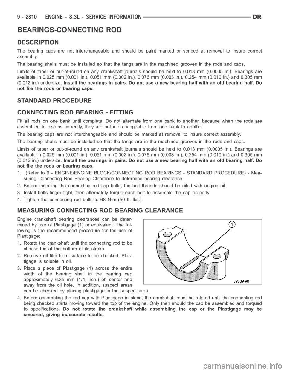
Engine crankshaft bearing clearances can be deter-
mined by use of Plastigage (1) or equivalent. The fol-
lowing is the recommended procedure for the use of
Plastigage:
1. Rotate the crankshaft until the connecting rod to be
checked is at the bottom of its stroke.
2. Remove oil film from surface to be checked. Plas-
tigage is soluble in oil.
3. Place a piece of Plastigage (1) across the entire
width of the bearing shell in the bearing cap
approximately 6.35 mm (1/4 inch.) off center and
away from the oil hole. In addition, suspect areas
can be checked by placing plastigage in the suspect area.
4. Before assembling the rod cap with Plastigage in place, the crankshaft must be rotated until the connecting rod
being checked starts moving toward the top of the engine. Only then should the cap be assembled and torqued
to specifications.Do not rotate the crankshaft while assembling the cap or the Plastigage maybe
smeared, giving inaccurate results.
Page 2126 of 5267
BEARINGS-CRANKSHAFT MAIN
DESCRIPTION
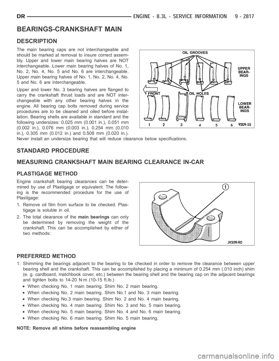
The main bearing caps are not interchangeable and
should be marked at removalto insure correct assem-
bly. Upper and lower main bearing halves are NOT
interchangeable. Lower main bearing halves of No. 1,
No. 2, No. 4, No. 5 and No. 6 are interchangeable.
Upper main bearing halves of No. 1, No. 2, No. 4, No.
5 and No. 6 are interchangeable.
Upper and lower No. 3 bearing halves are flanged to
carry the crankshaft thrust loads and are NOT inter-
changeable with any other bearing halves in the
engine. All bearing cap bolts removed during service
procedures are to be cleaned and oiled before instal-
lation. Bearing shells are available in standard and the
following undersizes: 0.025 mm (0.001 in.), 0.051 mm
(0.002 in.), 0.076 mm (0.003 in.), 0.254 mm (0.010
in.), 0.305 mm (0.012 in.) and 0.508 mm (0.020 in.).
Never install an undersize bearing that will reduce clearance below specifications.
STANDARD PROCEDURE
MEASURING CRANKSHAFT MAIN BEARING CLEARANCE IN-CAR
PLASTIGAGE METHOD
Engine crankshaft bearing clearances can be deter-
mined by use of Plastigage or equivalent. The follow-
ing is the recommended procedure for the use of
Plastigage:
1. Remove oil film from surface to be checked. Plas-
tigage is soluble in oil.
2. The total clearance of themain bearingscan only
be determined by removing the weight of the
crankshaft. This can be accomplished by either of
two methods:
PREFERRED METHOD
1. Shimming the bearings adjacent to the bearing to be checked in order to remove the clearance between upper
bearing shell and the crankshaft. Thiscanbeaccomplishedbyplacingaminimum of 0.254 mm (.010 inch) shim
(e. g. cardboard, matchbook cover, etc.) between the bearing shell and thebearing cap on the adjacent bearings
and tighten bolts to 14-20 Nꞏm (10-15 ft.lb.)
When checking No. 1 main bearing. Shim No. 2 main bearing.
When checking No. 2 main bearing. Shim No.1 and No. 3 main bearing.
When checking No.3 main bearing. Shim No. 2 and No. 4 main bearing.
When checking No. 4 main bearing. Shim No. 3 and No. 5 main bearing.
When checking No. 5 main bearing. Shim No. 4 and No. 6 main bearing.
When checking No. 6 main bearing. Shim No. 5 main bearing.
NOTE: Remove all shims before reassembling engine
Page 2407 of 5267
STEERING
DESCRIPTION
CAUTION: MOPARATF+4 is to be used in the power steering system. No other power steering or auto-
matic transmission fluid is to be used in the system. Damage may result to the power steering pump and
system if any other fluid is used, and do not overfill.
Power steering systems consist of:
Steering column
Rack and pinion steering gear
Belt driven hydraulic steering pump
Pump pressure and return hoses
Oil Cooler
OPERATION
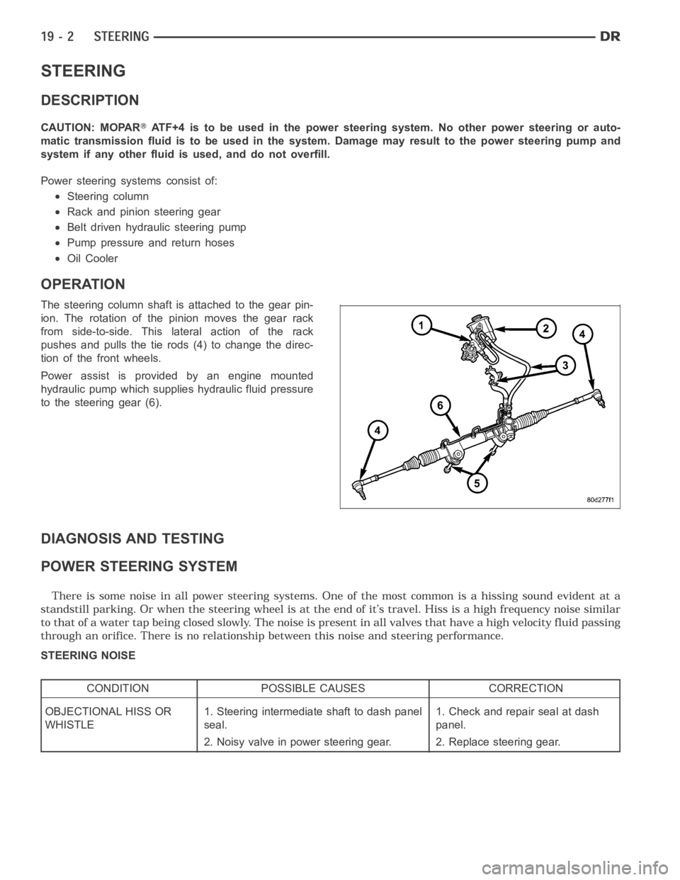
The steering column shaft isattached to the gear pin-
ion. The rotation of the pinion moves the gear rack
from side-to-side. This lateral action of the rack
pushes and pulls the tie rods (4) to change the direc-
tion of the front wheels.
Power assist is provided by an engine mounted
hydraulic pump which supplies hydraulic fluid pressure
to the steering gear (6).
DIAGNOSIS AND TESTING
POWER STEERING SYSTEM
STEERING NOISE
CONDITION POSSIBLE CAUSES CORRECTION
OBJECTIONAL HISS OR
WHISTLE1. Steering intermediate shaft to dash panel
seal.1. Check and repair seal at dash
panel.
2. Noisy valve in power steering gear. 2. Replace steering gear.
Page 2487 of 5267
FLUID
DESCRIPTION
NOTE: It is normal that some pressure will build up inside the reservoir, especially, with a warm vehicle. A
slight popping noise upon removal ofthe cap is normal. The fluid level should read between the ADD and
the FULL COLD marks. When the fluid is hotit should read between ADD and FULLHOT marks. Only add
fluid when the vehicle is cold.
The recommended fluid for the power steering system is Mopar
AT F + 4 .
Mopar
ATF+4, when new is red in color. The ATF+4 is dyed red so it can be identified from other fluids used in the
vehicle such as engine oil or antifreeze. The red color is not permanent andis not an indicator of fluid condition, As
the vehicle is driven, the ATF+4 will begin to look darker in color and may eventually become brown.THIS IS NOR-
MAL.ATF+4 also has a unique odor that may change with age. Consequently, odor and color cannot be used to
indicate the fluid condition or the need for a fluid change.
STANDARD PROCEDURE
POWER STEERING FLUID LEVEL CHECKING
WARNING: FLUID LEVEL SHOULD BE CHECKED WITH THE ENGINE OFF TO PREVENT PERSONAL INJURY
FROM MOVING PARTS.
CAUTION: MOPAR
ATF+4 is to be used in the power steering system. No other power steering or auto-
matic transmission fluid is to be used in the system. Damage may result to the power steering pump and
system if any other fluid is used, and do not overfill.
The power steering fluid level can be viewed on the dipstick attached to thefiller cap. There are two ranges listed
on the dipstick, COLD and HOT. Before opening power steering system, wipe the reservoir filler cap free of dirt and
debris. Remove the cap and check the fluid level on its dipstick. When the fluid is at normal ambient temperature,
approximately 21°C to 27°C (70°F to 80°F), the fluid level should read between the minimum and maximum area of
the cold range. When the fluid is hot, fluid level is allowed to read up to thehighest end of the HOT range. Only add
fluid when the vehicle is cold.
Use only Mopar
AT F + 4 .Do not overfill the power steering system.
Page 2892 of 5267
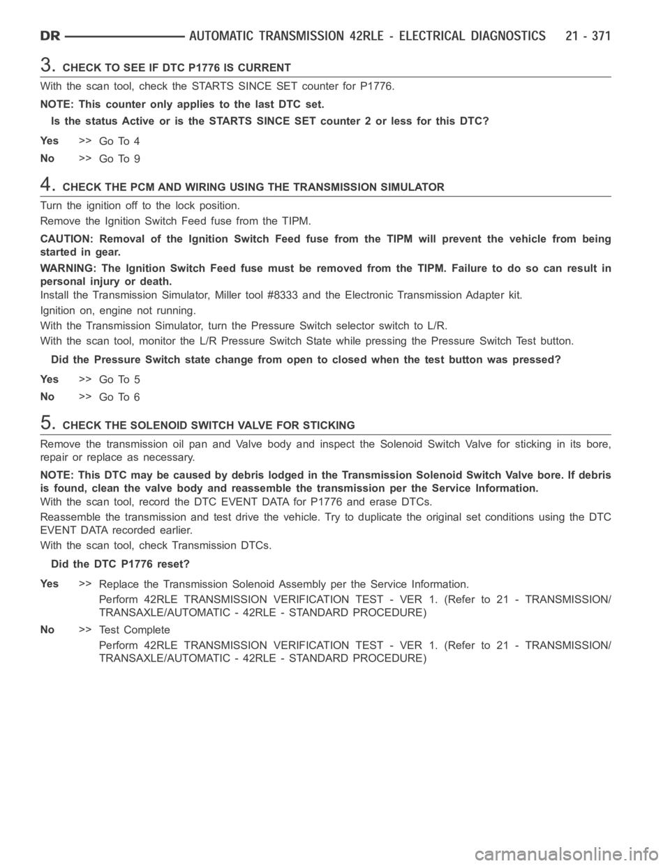
3.CHECK TO SEE IF DTC P1776 IS CURRENT
With the scan tool, check the STARTS SINCE SET counter for P1776.
NOTE: This counter only applies to the last DTC set.
Is the status Active or is the STARTS SINCE SET counter 2 or less for this DTC?
Ye s>>
Go To 4
No>>
Go To 9
4.CHECK THE PCM AND WIRING USING THE TRANSMISSION SIMULATOR
Turn the ignition off to the lock position.
Remove the Ignition Switch Feed fuse from the TIPM.
CAUTION: Removal of the Ignition Switch Feed fuse from the TIPM will prevent the vehicle from being
startedingear.
WARNING: The Ignition Switch Feed fuse must be removed from the TIPM. Failure to do so can result in
personal injury or death.
Install the Transmission Simulator,Miller tool #8333 and the ElectronicTransmission Adapter kit.
Ignition on, engine not running.
With the Transmission Simulator, turn the Pressure Switch selector switchtoL/R.
With the scan tool, monitor the L/R Pressure Switch State while pressing the Pressure Switch Test button.
Did the Pressure Switch state change from open to closed when the test button was pressed?
Ye s>>
Go To 5
No>>
Go To 6
5.CHECK THE SOLENOID SWITCH VALVE FOR STICKING
Remove the transmission oil pan and Valve body and inspect the Solenoid Switch Valve for sticking in its bore,
repair or replace as necessary.
NOTE: This DTC may be caused by debris lodged in the Transmission Solenoid Switch Valve bore. If debris
is found, clean the valve body and reassemble the transmission per the Service Information.
With the scan tool, record the DTC EVENT DATA for P1776 and erase DTCs.
Reassemble the transmission and test drive the vehicle. Try to duplicate the original set conditions using the DTC
EVENT DATA recorded earlier.
With the scan tool, check Transmission DTCs.
Did the DTC P1776 reset?
Ye s>>
Replace the Transmission Solenoid Assembly per the Service Information.
Perform 42RLE TRANSMISSION VERIFICATION TEST - VER 1. (Refer to 21 - TRANSMISSION/
TRANSAXLE/AUTOMATIC - 42RLE - STANDARD PROCEDURE)
No>>
Te s t C o m p l e t e
Perform 42RLE TRANSMISSION VERIFICATION TEST - VER 1. (Refer to 21 - TRANSMISSION/
TRANSAXLE/AUTOMATIC - 42RLE - STANDARD PROCEDURE)
Page 2968 of 5267
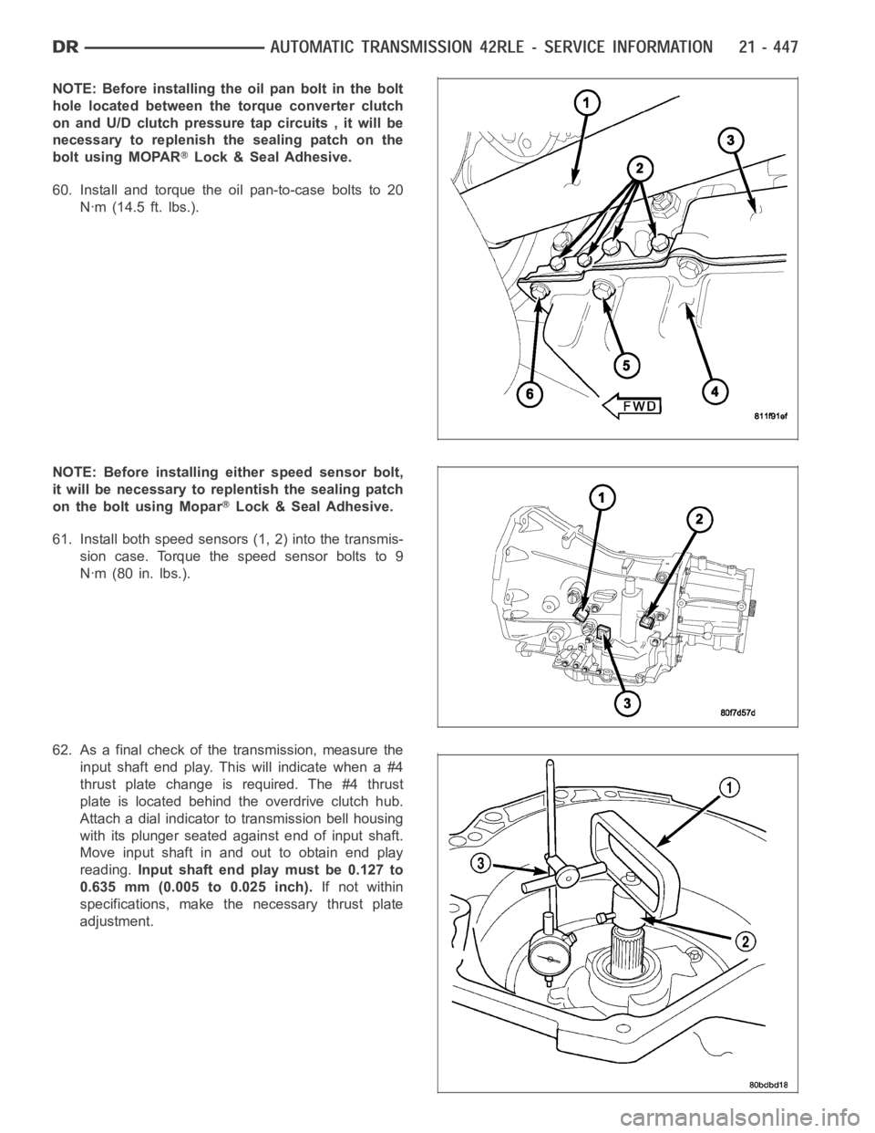
NOTE: Before installing the oil pan bolt in the bolt
hole located between the torque converter clutch
on and U/D clutch pressure tap circuits , it will be
necessary to replenish the sealing patch on the
bolt using MOPAR
Lock & Seal Adhesive.
60. Install and torque the oil pan-to-case bolts to 20
Nꞏm (14.5 ft. lbs.).
NOTE: Before installing either speed sensor bolt,
it will be necessary to replentish the sealing patch
on the bolt using Mopar
Lock & Seal Adhesive.
61. Install both speed sensors (1, 2) into the transmis-
sion case. Torque the speed sensor bolts to 9
Nꞏm (80 in. lbs.).
62. As a final check of the transmission, measure the
input shaft end play. This will indicate when a #4
thrust plate change is required. The #4 thrust
plate is located behind the overdrive clutch hub.
Attach a dial indicator to transmission bell housing
with its plunger seated against end of input shaft.
Move input shaft in and out to obtain end play
reading.Input shaft end play must be 0.127 to
0.635 mm (0.005 to 0.025 inch).If not within
specifications, make the necessary thrust plate
adjustment.
Page 3000 of 5267
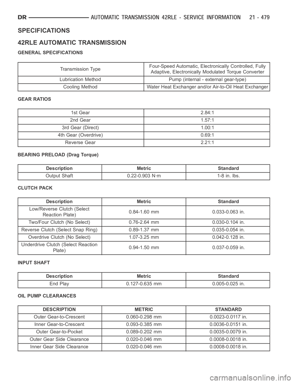
SPECIFICATIONS
42RLE AUTOMATIC TRANSMISSION
GENERAL SPECIFICATIONS
Transmission TypeFour-Speed Automatic, Electronically Controlled, Fully
Adaptive, Electronically Modulated Torque Converter
Lubrication Method Pump (internal - external gear-type)
Cooling Method Water Heat Exchanger and/or Air-to-Oil Heat Exchanger
GEAR RATIOS
1st Gear 2.84:1
2nd Gear 1.57:1
3rd Gear (Direct) 1.00:1
4th Gear (Overdrive) 0.69:1
Reverse Gear 2.21:1
BEARING PRELOAD (Drag Torque)
Description Metric Standard
Output Shaft 0.22-0.903 Nꞏm 1-8 in. lbs.
CLUTCH PACK
Description Metric Standard
Low/Reverse Clutch (Select
Reaction Plate)0.84-1.60 mm 0.033-0.063 in.
Two/Four Clutch (No Select) 0.76-2.64 mm 0.030-0.104 in.
Reverse Clutch (Select Snap Ring) 0.89-1.37 mm 0.035-0.054 in.
Overdrive Clutch (No Select) 1.07-3.25 mm 0.042-0.128 in.
Underdrive Clutch (Select Reaction
Plate)0.94-1.50 mm 0.037-0.059 in.
INPUT SHAFT
Description Metric Standard
End Play 0.127-0.635 mm 0.005-0.025 in.
OIL PUMP CLEARANCES
DESCRIPTION METRIC STANDARD
Outer Gear-to-Crescent 0.060-0.298 mm 0.0023-0.0117 in.
Inner Gear-to-Crescent 0.093-0.385 mm 0.0036-0.0151 in.
Outer Gear-to-Pocket 0.089-0.202 mm 0.0035-0.0079 in.
Outer Gear Side Clearance 0.020-0.046 mm 0.0008-0.0018 in.
Inner Gear Side Clearance 0.020-0.046 mm 0.0008-0.0018 in.
Page 3015 of 5267
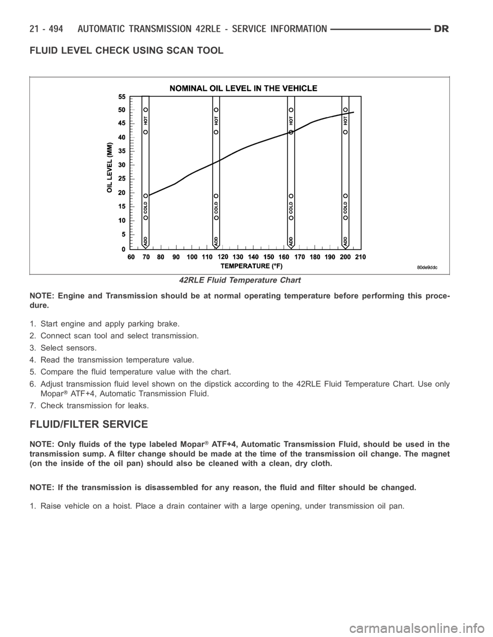
FLUID LEVEL CHECK USING SCAN TOOL
NOTE: Engine and Transmission should be at normal operating temperature before performing this proce-
dure.
1. Start engine and apply parking brake.
2. Connect scan tool and select transmission.
3. Select sensors.
4. Read the transmission temperature value.
5. Compare the fluid temperature value with the chart.
6. Adjust transmission fluid level shown on the dipstick according to the 42RLE Fluid Temperature Chart. Use only
Mopar
ATF+4, Automatic Transmission Fluid.
7. Check transmission for leaks.
FLUID/FILTER SERVICE
NOTE: Only fluids of the type labeled MoparATF+4, Automatic Transmission Fluid, should be used in the
transmission sump. A filter change should be made at the time of the transmission oil change. The magnet
(on the inside of the oil pan) should also be cleaned with a clean, dry cloth.
NOTE: If the transmission is disassembled for any reason, the fluid and filter should be changed.
1. Raise vehicle on a hoist. Place a drain container with a large opening, under transmission oil pan.
42RLE Fluid Temperature Chart