2006 DODGE RAM SRT-10 service reset
[x] Cancel search: service resetPage 3307 of 5267
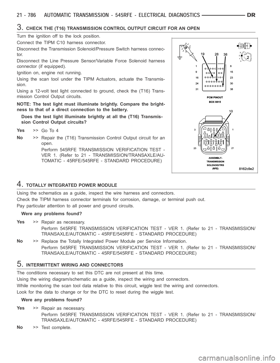
3.CHECK THE (T16) TRANSMISSION CONTROL OUTPUT CIRCUIT FOR AN OPEN
Turn the ignition off to the lock position.
Connect the TIPM C10 harness connector.
Disconnect the Transmission Solenoid/Pressure Switch harness connec-
tor.
Disconnect the Line Pressure Sensor/Variable Force Solenoid harness
connector (if equipped).
Ignition on, engine not running.
Using the scan tool under the TIPM Actuators, actuate the Transmis-
sion.
Using a 12-volt test light connected to ground, check the (T16) Trans-
mission Control Output circuits.
NOTE: The test light must illuminate brightly. Compare the bright-
ness to that of a direct connection to the battery.
Does the test light illuminate brightly at all the (T16) Transmis-
sion Control Output circuits?
Ye s>>
Go To 4
No>>
Repair the (T16) Transmission Control Output circuit for an
open.
Perform 545RFE TRANSMISSION VERIFICATION TEST -
VER 1. (Refer to 21 - TRANSMISSION/TRANSAXLE/AU-
TOMATIC - 45RFE/545RFE - STANDARD PROCEDURE)
4.TOTALLY INTEGRATED POWER MODULE
Using the schematics as a guide, inspect the wire harness and connectors.
Check the TIPM harness connector terminals for corrosion, damage, or terminal push out.
Pay particular attention to all power and ground circuits.
Were any problems found?
Ye s>>
Repair as necessary.
Perform 545RFE TRANSMISSION VERIFICATION TEST - VER 1. (Refer to 21 - TRANSMISSION/
TRANSAXLE/AUTOMATIC - 45RFE/545RFE - STANDARD PROCEDURE)
No>>
Replace the Totally Integrated Power Module per Service Information.
Perform 545RFE TRANSMISSION VERIFICATION TEST - VER 1. (Refer to 21 - TRANSMISSION/
TRANSAXLE/AUTOMATIC - 45RFE/545RFE - STANDARD PROCEDURE)
5.INTERMITTENT WIRING AND CONNECTORS
The conditions necessary to set this DTC are not present at this time.
Using the wiring diagram/schematic as a guide, inspect the wiring and connectors.
While monitoring the scan tool data relative to this circuit, wiggle test the wiring and connectors.
Look for the data to change or for the DTC to reset during the wiggle test.
Were any problems found?
Ye s>>
Repair as necessary.
Perform 545RFE TRANSMISSION VERIFICATION TEST - VER 1. (Refer to 21 - TRANSMISSION/
TRANSAXLE/AUTOMATIC - 45RFE/545RFE - STANDARD PROCEDURE)
No>>
Te s t c o m p l e t e .
Page 3313 of 5267
3.TOTALLY INTEGRATED POWER MODULE
Using the schematics as a guide, inspect the wire harness and connectors.
Check the TIPM harness connector terminals for corrosion, damage, or terminal push out.
Pay particular attention to all power and ground circuits.
Were any problems found?
Ye s>>
Repair as necessary.
Perform 545RFE TRANSMISSION VERIFICATION TEST - VER 1. (Refer to 21 - TRANSMISSION/
TRANSAXLE/AUTOMATIC - 45RFE/545RFE - STANDARD PROCEDURE)
No>>
Replace the Totally Integrated Power Module per Service Information.
Perform 545RFE TRANSMISSION VERIFICATION TEST - VER 1. (Refer to 21 - TRANSMISSION/
TRANSAXLE/AUTOMATIC - 45RFE/545RFE - STANDARD PROCEDURE)
4.INTERMITTENT WIRING AND CONNECTORS
The conditions necessary to set this DTC are not present at this time.
Using the wiring diagram/schematic as a guide, inspect the wiring and connectors.
While monitoring the scan tool data relative to this circuit, wiggle test the wiring and connectors.
Look for the data to change or for the DTC to reset during the wiggle test.
Were any problems found?
Ye s>>
Repair as necessary.
Perform 545RFE TRANSMISSION VERIFICATION TEST - VER 1. (Refer to 21 - TRANSMISSION/
TRANSAXLE/AUTOMATIC - 45RFE/545RFE - STANDARD PROCEDURE)
No>>
Te s t c o m p l e t e .
Page 3325 of 5267
14.CHECK IF DTC RESET
Did the DTC P1736 reset during the road test?
Ye s>>
Go To 15
No>>
Go To 16
15.LIST OF POSSIBLE CAUSES
If any other DTC’s set during the road test, refer to the appropriate symptom in the Transmission category.
If no other DTC’s set during the road test, below is a list of possible causes, but not strictly limited to those:
Check for excessive debris in the Transmission Oil pan, plugged, cracked,or split Primary Transmission Oil Filter
and/or seal.
Check for cuts or missing #7 and #5 check balls in the main valve body.
Check the 4C and UD accumulator pistons and seals, UD bleed orifice, and theSolenoid Switch Valve and Plugs
in the main valve body.
Check the UD clutch piston seals, reaction shaft support seal rings, and the flatness of the pump valve body and
pump housing faces.
Check the 4C clutch piston seals, and bleed orifice.
Check the UD clutch piston seals, reaction shaft support seal rings, and dribbler assemblies, and the flatness of the
pump valve body and pump housing faces.
View repair
Repair
Repair as necessary. Refer to the Service Information for proper repair procedures.
Perform 45RFE/545RFE TRANSMISSION VERIFICATION TEST - VER 1. (Refer to 21- TRANSMIS-
SION/TRANSAXLE/AUTOMATIC - 45RFE/545RFE - STANDARD PROCEDURE)
16.INTERMITTENT DTC
The conditions necessary to set this DTC are not present at this time.
Use the DTC EVENT DATA to help identify the conditions and/or possible causes that may have caused the DTC
to set.
Check for any Service Information Tune-ups or Technical Service Bulletins that may apply.
Where there any problems found?
Ye s>>
Repair as necessary.
Perform 45RFE/545RFE TRANSMISSION VERIFICATION TEST - VER 1. (Refer to 21- TRANSMIS-
SION/TRANSAXLE/AUTOMATIC - 45RFE/545RFE - STANDARD PROCEDURE)
No>>
Te s t C o m p l e t e .
Page 3351 of 5267
Monitor the MS Solenoid LED on the Transmission Simulator.
Did the MS Solenoid LED on the Transmission Simulator blink on and off?
Ye s>>
Replace the Transmission Solenoid/TRS Assembly per the Service Information.
Perform 45RFE/545RFE TRANSMISSION VERIFICATION TEST - VER 1. (Refer to 21- TRANSMIS-
SION/TRANSAXLE/AUTOMATIC - 45RFE/545RFE - STANDARD PROCEDURE)
No>>
Go To 3
3.TRANSMISSION SOLENOID/TRS ASSEMBLY
With the scan tool, continue to actuate the MS Solenoid for the period of 2 minutes with the Transmission Simulator
still connected.
After 2 minutes of actuation, with the scan tool, stop the actuation and check for transmission DTCs.
Did the DTC P2706 reset during the actuation test?
Ye s>>
Go To 4
No>> Perform 45RFE/545RFE TRANSMISSION VERIFICATION TEST - VER 1. (Refer to21 - TRANSMIS-
SION/TRANSAXLE/AUTOMATIC - 45RFE/545RFE - STANDARD PROCEDURE)
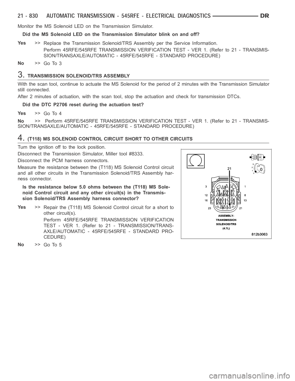
4.(T118) MS SOLENOID CONTROL CIRCUIT SHORT TO OTHER CIRCUITS
Turn the ignition off to the lock position.
Disconnect the Transmission Simulator, Miller tool #8333.
Disconnect the PCM harness connectors.
Measure the resistance between the (T118) MS Solenoid Control circuit
and all other circuits in the Transmission Solenoid/TRS Assembly har-
ness connector.
Is the resistance below 5.0 ohms between the (T118) MS Sole-
noid Control circuit and any other circuit(s) in the Transmis-
sion Solenoid/TRS Assembly harness connector?
Ye s>>
Repair the (T118) MS Solenoid Control circuit for a short to
other circuit(s).
Perform 45RFE/545RFE TRANSMISSION VERIFICATION
TEST - VER 1. (Refer to 21 - TRANSMISSION/TRANS-
AXLE/AUTOMATIC - 45RFE/545RFE - STANDARD PRO-
CEDURE)
No>>
Go To 5
Page 3361 of 5267
45RFE/545RFE PRE-DIAGNOSTIC TROUBLESHOOTING PROCEDURE
For a complete wiring diagramRefer to Section 8W.
1.
Perform the following before attempting any diagnostic procedures:
Check the transmission fluid level. Ifthe fluid level is low, locate and repair any leaks and fill the transmission
to the proper level. Refer to the appropriate Service Information for procedures. Many transmission symptoms
can be caused by a low fluid level.
Check the battery. To avoid false diagnosis, testing should only be performed with the battery fully charged.
With the scan tool, read Engine (PCM) DTCs. If DTCs are present, refer to theDriveability Category and per-
form to the appropriate diagnostic procedure(s) before proceeding.
With the scan tool, read Transmission (TCM) DTCs. Record all Stored, Active, and Pending DTC information.
Diagnose any Pending DTC as a matured DTC.
With the scan tool, read DTC EVENT DATA.Use this data to identify the conditions in which the DTC was set.
Performing a Battery Disconnect will clear all DTC EVENT DATA and reset alllearned Transmission values to
the default values, which may temporarily result in erratic shift schedules.
With the scan tool, perform the Shift Lever Position Test. If the test does not pass, refer to the diagnostic
procedure for P0706 Transmission Range Sensor Rationality.
For Gear Ratio Error DTCs, use the scan tool to view CVI Monitor data. Read and record the Clutch Volume
Index information.
Use the wiring diagram as a guide. Inspect the wiring and connectors related to this circuit. Repair as neces-
sary.
Refer to the When Monitored and Set Conditions for this DTC. DTCs can set at ignition on, at start up, after
driving under specific conditions and after diagnostic monitors have beenrun.
Refer to applicable Technical Service Bulletins (TSBs) for controller software update information. Some condi-
tions can be corrected by upgrading the Engine (PCM) or Transmission (TCM)controller software.
Refer to any Service Information Tune Ups or Technical Service Bulletins that apply.
Were there any repairs made that fixed the vehicle?
Ye s>>
Testing complete.
Perform 45RFE/545RFE TRANSMISSION VERIFICATION TEST - VER 1. (Refer to 21- TRANSMIS-
SION/TRANSAXLE/AUTOMATIC - 45RFE/545RFE - STANDARD PROCEDURE)
No>>
Refer to the Transmission category and perform the appropriate diagnostic procedure(s).
Page 3549 of 5267
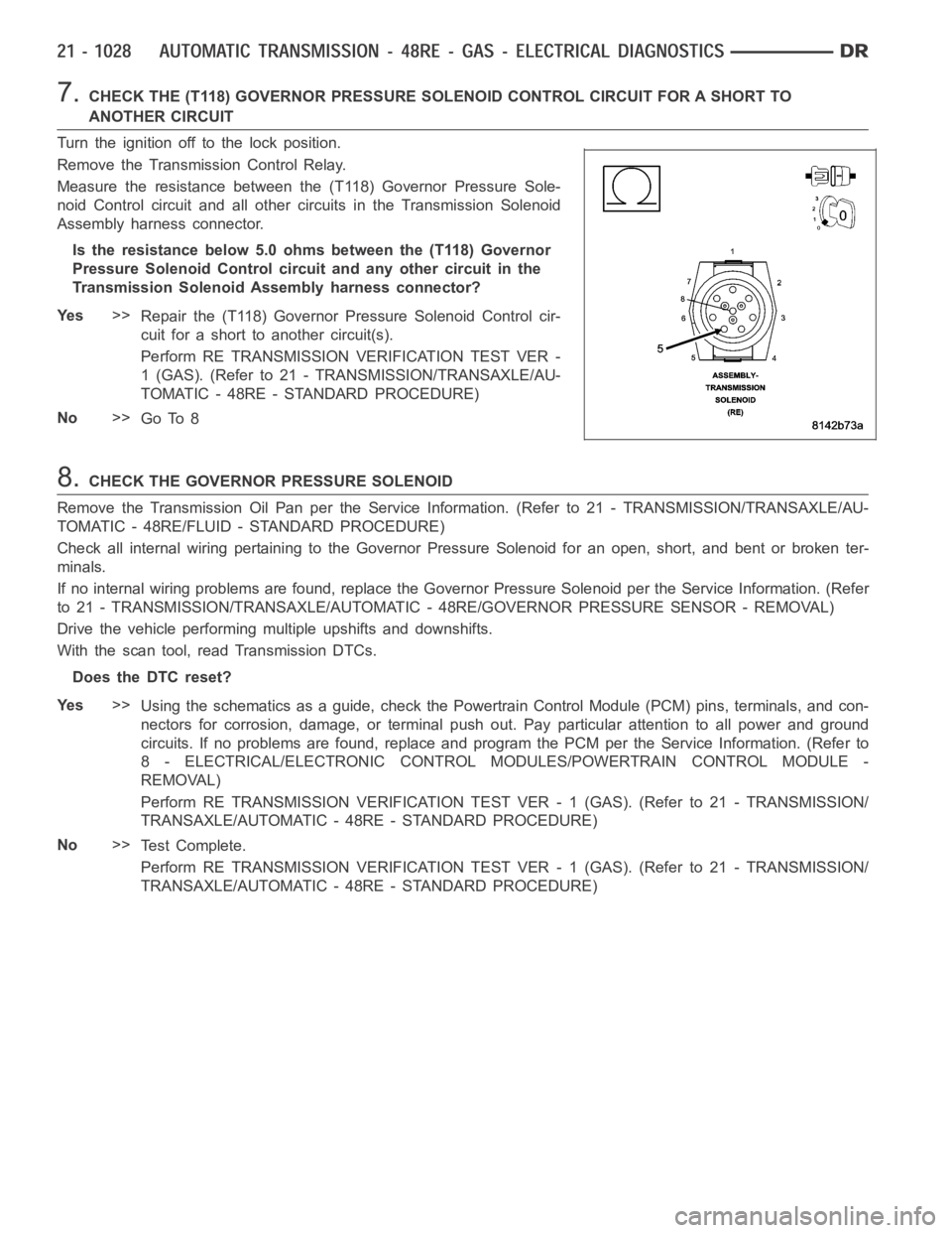
7.CHECK THE (T118) GOVERNOR PRESSURE SOLENOID CONTROL CIRCUIT FOR A SHORT TO
ANOTHER CIRCUIT
Turn the ignition off to the lock position.
Remove the Transmission Control Relay.
Measure the resistance between the (T118) Governor Pressure Sole-
noid Control circuit and all other circuits in the Transmission Solenoid
Assembly harness connector.
Is the resistance below 5.0 ohms between the (T118) Governor
Pressure Solenoid Control circuit and any other circuit in the
Transmission Solenoid Assembly harness connector?
Ye s>>
Repair the (T118) Governor Pressure Solenoid Control cir-
cuit for a short to another circuit(s).
Perform RE TRANSMISSION VERIFICATION TEST VER -
1 (GAS). (Refer to 21 - TRANSMISSION/TRANSAXLE/AU-
TOMATIC - 48RE - STANDARD PROCEDURE)
No>>
Go To 8
8.CHECK THE GOVERNOR PRESSURE SOLENOID
Remove the Transmission Oil Pan per the Service Information. (Refer to 21 -TRANSMISSION/TRANSAXLE/AU-
TOMATIC - 48RE/FLUID - STANDARD PROCEDURE)
Check all internal wiring pertaining to the Governor Pressure Solenoid for an open, short, and bent or broken ter-
minals.
If no internal wiring problems are found, replace the Governor Pressure Solenoid per the Service Information. (Refer
to 21 - TRANSMISSION/TRANSAXLE/AUTOMATIC - 48RE/GOVERNOR PRESSURE SENSOR - REMOVAL)
Drive the vehicle performing multiple upshifts and downshifts.
With the scan tool, read Transmission DTCs.
Does the DTC reset?
Ye s>>
Using the schematics as a guide, check the Powertrain Control Module (PCM)pins, terminals, and con-
nectors for corrosion, damage, or terminal push out. Pay particular attention to all power and ground
circuits. If no problems are found, replace and program the PCM per the Service Information. (Refer to
8 - ELECTRICAL/ELECTRONIC CONTROL MODULES/POWERTRAIN CONTROL MODULE -
REMOVAL)
Perform RE TRANSMISSION VERIFICATION TEST VER - 1 (GAS). (Refer to 21 - TRANSMISSION/
TRANSAXLE/AUTOMATIC - 48RE - STANDARD PROCEDURE)
No>>
Te s t C o m p l e t e .
Perform RE TRANSMISSION VERIFICATION TEST VER - 1 (GAS). (Refer to 21 - TRANSMISSION/
TRANSAXLE/AUTOMATIC - 48RE - STANDARD PROCEDURE)
Page 3557 of 5267
2.CHECK IF THE DTC IS CURRENT
Ignition on, engine not running.
With the scan tool, read Engine DTCs.
Record the Freeze Frame data for the reported DTC.
With the scan tool, erase DTCs.
Turn the ignition off to the lock position.
Using the Freeze Frame data recorded earlier, try to duplicate the conditions in which the DTC originally set.
NOTE: It may be necessary to road test the vehicle to duplicate the originalset conditions.
With the scan tool, read Engine DTCs.
Did the DTC reset?
Ye s>>
Go To 3
No>>
Go To 12
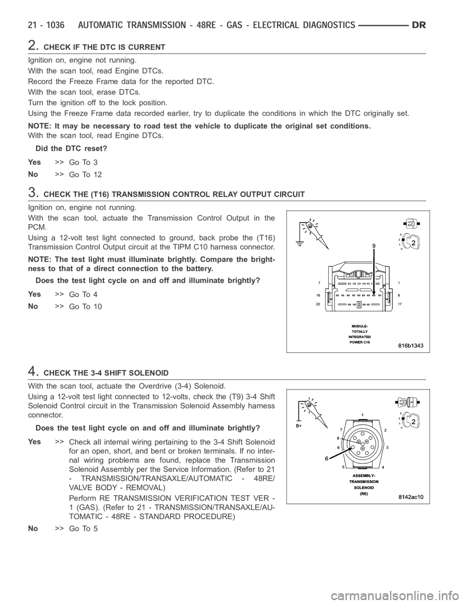
3.CHECK THE (T16) TRANSMISSION CONTROL RELAY OUTPUT CIRCUIT
Ignition on, engine not running.
With the scan tool, actuate the Transmission Control Output in the
PCM.
Using a 12-volt test light connected to ground, back probe the (T16)
Transmission Control Output circuit at the TIPM C10 harness connector.
NOTE: The test light must illuminate brightly. Compare the bright-
ness to that of a direct connection to the battery.
Does the test light cycle on and off and illuminate brightly?
Ye s>>
Go To 4
No>>
Go To 10
4.CHECK THE 3-4 SHIFT SOLENOID
With the scan tool, actuate the Overdrive (3-4) Solenoid.
Using a 12-volt test light connected to 12-volts, check the (T9) 3-4 Shift
Solenoid Control circuit in the Transmission Solenoid Assembly harness
connector.
Does the test light cycle on and off and illuminate brightly?
Ye s>>
Check all internal wiring pertaining to the 3-4 Shift Solenoid
for an open, short, and bent or broken terminals. If no inter-
nal wiring problems are found, replace the Transmission
Solenoid Assembly per the Service Information. (Refer to 21
- TRANSMISSION/TRANSAXLE/AUTOMATIC - 48RE/
VA LV E B O D Y - R E M O VA L )
Perform RE TRANSMISSION VERIFICATION TEST VER -
1 (GAS). (Refer to 21 - TRANSMISSION/TRANSAXLE/AU-
TOMATIC - 48RE - STANDARD PROCEDURE)
No>>
Go To 5
Page 3573 of 5267
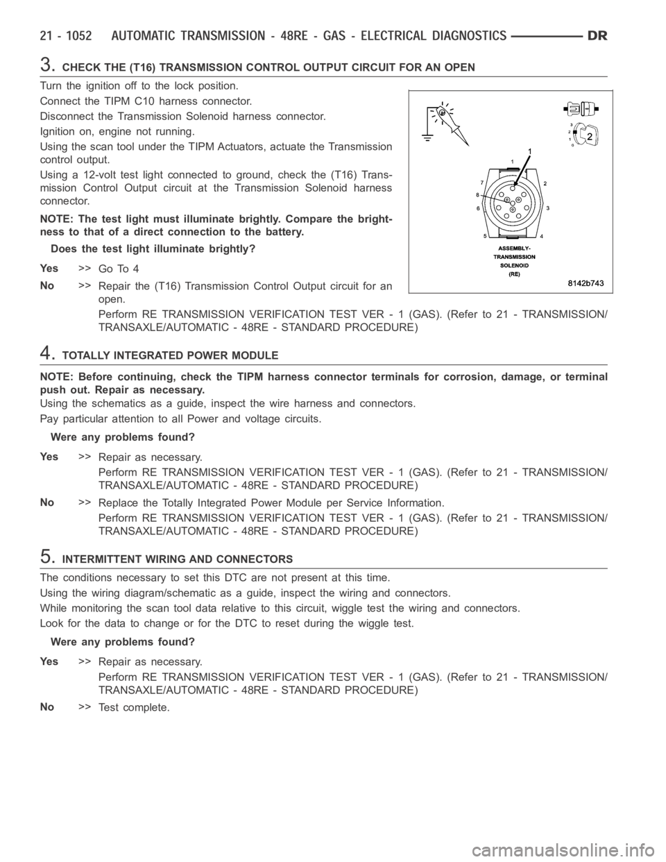
3.CHECK THE (T16) TRANSMISSION CONTROL OUTPUT CIRCUIT FOR AN OPEN
Turn the ignition off to the lock position.
Connect the TIPM C10 harness connector.
Disconnect the Transmission Solenoid harness connector.
Ignition on, engine not running.
Using the scan tool under the TIPM Actuators, actuate the Transmission
control output.
Using a 12-volt test light connected to ground, check the (T16) Trans-
mission Control Output circuit at the Transmission Solenoid harness
connector.
NOTE: The test light must illuminate brightly. Compare the bright-
ness to that of a direct connection to the battery.
Does the test light illuminate brightly?
Ye s>>
Go To 4
No>>
Repair the (T16) Transmission Control Output circuit for an
open.
Perform RE TRANSMISSION VERIFICATION TEST VER - 1 (GAS). (Refer to 21 - TRANSMISSION/
TRANSAXLE/AUTOMATIC - 48RE - STANDARD PROCEDURE)
4.TOTALLY INTEGRATED POWER MODULE
NOTE: Before continuing, check the TIPM harness connector terminals for corrosion, damage, or terminal
push out. Repair as necessary.
Using the schematics as a guide, inspect the wire harness and connectors.
Pay particular attention to allPower and voltage circuits.
Were any problems found?
Ye s>>
Repair as necessary.
Perform RE TRANSMISSION VERIFICATION TEST VER - 1 (GAS). (Refer to 21 - TRANSMISSION/
TRANSAXLE/AUTOMATIC - 48RE - STANDARD PROCEDURE)
No>>
Replace the Totally Integrated Power Module per Service Information.
Perform RE TRANSMISSION VERIFICATION TEST VER - 1 (GAS). (Refer to 21 - TRANSMISSION/
TRANSAXLE/AUTOMATIC - 48RE - STANDARD PROCEDURE)
5.INTERMITTENT WIRING AND CONNECTORS
The conditions necessary to set this DTC are not present at this time.
Using the wiring diagram/schematic as a guide, inspect the wiring and connectors.
While monitoring the scan tool data relative to this circuit, wiggle test the wiring and connectors.
Look for the data to change or for the DTC to reset during the wiggle test.
Were any problems found?
Ye s>>
Repair as necessary.
Perform RE TRANSMISSION VERIFICATION TEST VER - 1 (GAS). (Refer to 21 - TRANSMISSION/
TRANSAXLE/AUTOMATIC - 48RE - STANDARD PROCEDURE)
No>>
Te s t c o m p l e t e .