2006 DODGE RAM SRT-10 service reset
[x] Cancel search: service resetPage 2726 of 5267
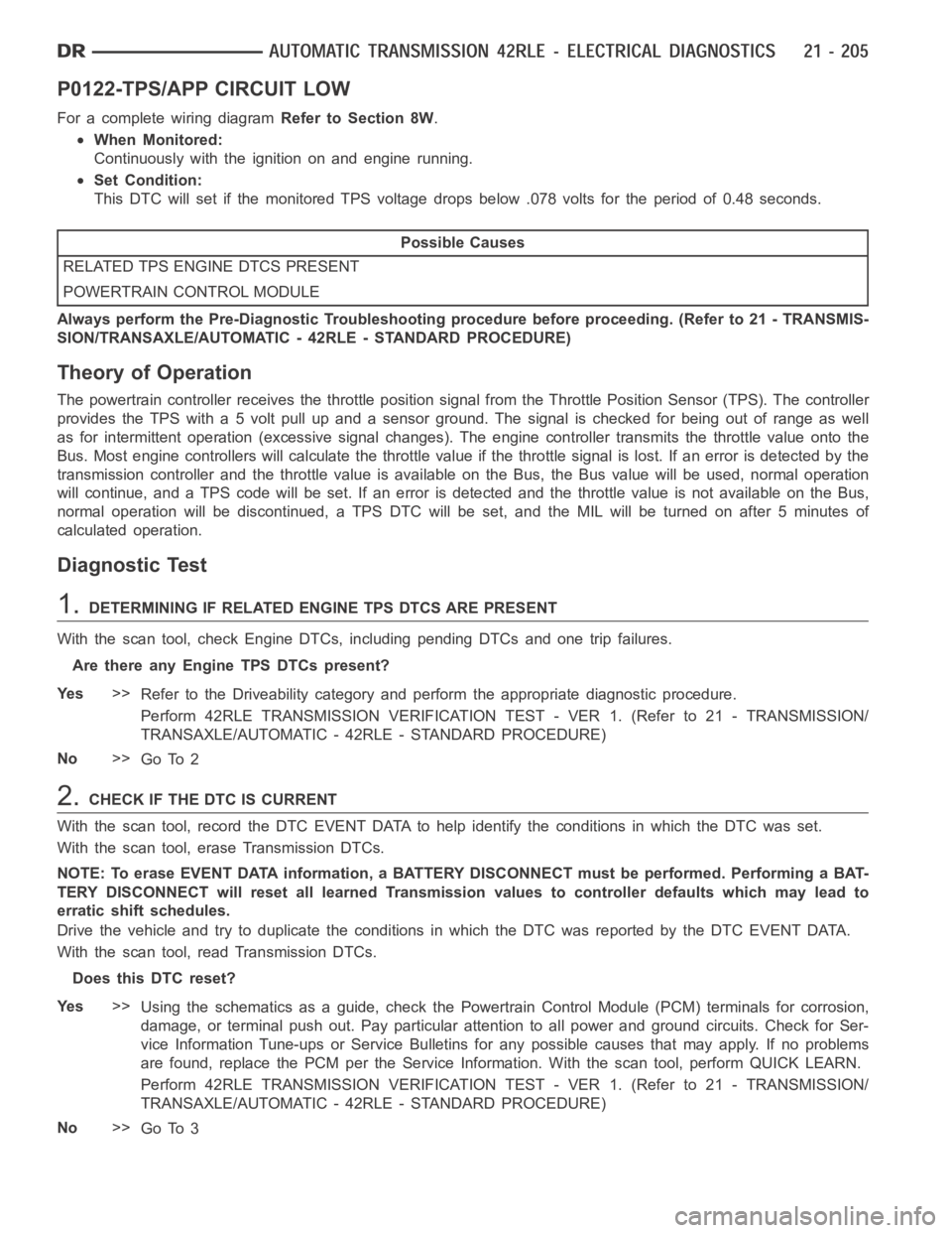
P0122-TPS/APP CIRCUIT LOW
For a complete wiring diagramRefer to Section 8W.
When Monitored:
Continuously with the ignition on and engine running.
Set Condition:
This DTC will set if the monitored TPS voltage drops below .078 volts for theperiod of 0.48 seconds.
Possible Causes
RELATED TPS ENGINE DTCS PRESENT
POWERTRAIN CONTROL MODULE
Always perform the Pre-Diagnostic Troubleshooting procedure before proceeding. (Refer to 21 - TRANSMIS-
SION/TRANSAXLE/AUTOMATIC - 42RLE - STANDARD PROCEDURE)
Theory of Operation
The powertrain controller receives the throttle position signal from theThrottle Position Sensor (TPS). The controller
provides the TPS with a 5 volt pull up and a sensor ground. The signal is checked for being out of range as well
as for intermittent operation (excessive signal changes). The engine controller transmits the throttle value onto the
Bus. Most engine controllers will calculate the throttle value if the throttle signal is lost. If an error is detected by the
transmission controller and the throttle value is available on the Bus, the Bus value will be used, normal operation
will continue, and a TPS code will be set. If an error is detected and the throttle value is not available on the Bus,
normal operation will be discontinued, a TPS DTC will be set, and the MIL will be turned on after 5 minutes of
calculated operation.
Diagnostic Test
1.DETERMINING IF RELATED ENGINE TPS DTCS ARE PRESENT
With the scan tool, check Engine DTCs, including pending DTCs and one trip failures.
Are there any Engine TPS DTCs present?
Ye s>>
Refer to the Driveability category and perform the appropriate diagnostic procedure.
Perform 42RLE TRANSMISSION VERIFICATION TEST - VER 1. (Refer to 21 - TRANSMISSION/
TRANSAXLE/AUTOMATIC - 42RLE - STANDARD PROCEDURE)
No>>
Go To 2
2.CHECK IF THE DTC IS CURRENT
With the scan tool, record the DTC EVENT DATA to help identify the conditionsinwhichtheDTCwasset.
With the scan tool, erase Transmission DTCs.
NOTE: To erase EVENT DATA information, a BATTERY DISCONNECT must be performed. Performing a BAT-
TERY DISCONNECT will reset all learned Transmission values to controllerdefaults which may lead to
erratic shift schedules.
Drive the vehicle and try to duplicate the conditions in which the DTC was reported by the DTC EVENT DATA.
With the scan tool, read Transmission DTCs.
Does this DTC reset?
Ye s>>
Using the schematics as a guide, check the Powertrain Control Module (PCM)terminals for corrosion,
damage, or terminal push out. Pay particular attention to all power and ground circuits. Check for Ser-
vice Information Tune-ups or Service Bulletins for any possible causes that may apply. If no problems
are found, replace the PCM per the Service Information. With the scan tool,perform QUICK LEARN.
Perform 42RLE TRANSMISSION VERIFICATION TEST - VER 1. (Refer to 21 - TRANSMISSION/
TRANSAXLE/AUTOMATIC - 42RLE - STANDARD PROCEDURE)
No>>
Go To 3
Page 2728 of 5267
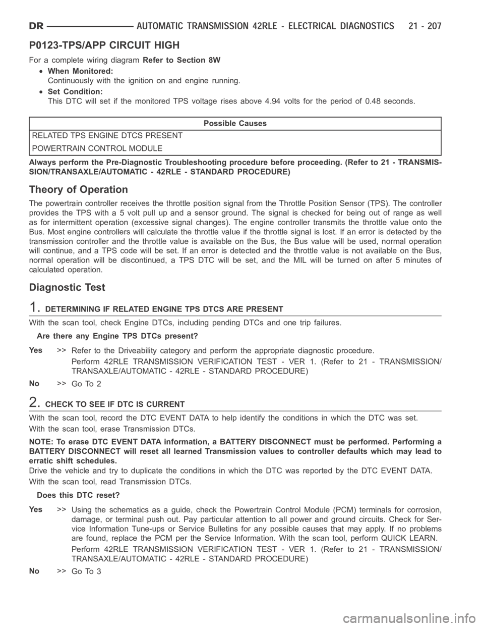
P0123-TPS/APP CIRCUIT HIGH
For a complete wiring diagramRefer to Section 8W
When Monitored:
Continuously with the ignition on and engine running.
Set Condition:
This DTC will set if the monitored TPS voltage rises above 4.94 volts for theperiod of 0.48 seconds.
Possible Causes
RELATED TPS ENGINE DTCS PRESENT
POWERTRAIN CONTROL MODULE
Always perform the Pre-Diagnostic Troubleshooting procedure before proceeding. (Refer to 21 - TRANSMIS-
SION/TRANSAXLE/AUTOMATIC - 42RLE - STANDARD PROCEDURE)
Theory of Operation
The powertrain controller receives the throttle position signal from theThrottle Position Sensor (TPS). The controller
provides the TPS with a 5 volt pull up and a sensor ground. The signal is checked for being out of range as well
as for intermittent operation (excessive signal changes). The engine controller transmits the throttle value onto the
Bus. Most engine controllers will calculate the throttle value if the throttle signal is lost. If an error is detected by the
transmission controller and the throttle value is available on the Bus, the Bus value will be used, normal operation
will continue, and a TPS code will be set. If an error is detected and the throttle value is not available on the Bus,
normal operation will be discontinued, a TPS DTC will be set, and the MIL will be turned on after 5 minutes of
calculated operation.
Diagnostic Test
1.DETERMINING IF RELATED ENGINE TPS DTCS ARE PRESENT
With the scan tool, check Engine DTCs, including pending DTCs and one trip failures.
Are there any Engine TPS DTCs present?
Ye s>>
Refer to the Driveability category and perform the appropriate diagnostic procedure.
Perform 42RLE TRANSMISSION VERIFICATION TEST - VER 1. (Refer to 21 - TRANSMISSION/
TRANSAXLE/AUTOMATIC - 42RLE - STANDARD PROCEDURE)
No>>
Go To 2
2.CHECK TO SEE IF DTC IS CURRENT
With the scan tool, record the DTC EVENT DATA to help identify the conditionsinwhichtheDTCwasset.
With the scan tool, erase Transmission DTCs.
NOTE: To erase DTC EVENT DATA information, a BATTERY DISCONNECT must be performed. Performing a
BATTERY DISCONNECT will reset all learned Transmission values to controller defaults which may lead to
erratic shift schedules.
Drive the vehicle and try to duplicate the conditions in which the DTC was reported by the DTC EVENT DATA.
With the scan tool, read Transmission DTCs.
Does this DTC reset?
Ye s>>
Using the schematics as a guide, check the Powertrain Control Module (PCM)terminals for corrosion,
damage, or terminal push out. Pay particular attention to all power and ground circuits. Check for Ser-
vice Information Tune-ups or Service Bulletins for any possible causes that may apply. If no problems
are found, replace the PCM per the Service Information. With the scan tool,perform QUICK LEARN.
Perform 42RLE TRANSMISSION VERIFICATION TEST - VER 1. (Refer to 21 - TRANSMISSION/
TRANSAXLE/AUTOMATIC - 42RLE - STANDARD PROCEDURE)
No>>
Go To 3
Page 2739 of 5267
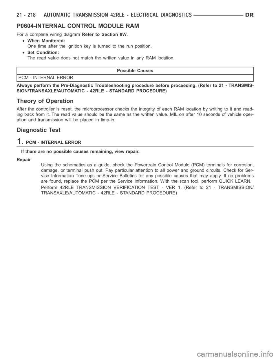
P0604-INTERNAL CONTROL MODULE RAM
For a complete wiring diagramRefer to Section 8W.
When Monitored:
One time after the ignition key is turned to the run position.
Set Condition:
The read value does not match the written value in any RAM location.
Possible Causes
PCM - INTERNAL ERROR
Always perform the Pre-Diagnostic Troubleshooting procedure before proceeding. (Refer to 21 - TRANSMIS-
SION/TRANSAXLE/AUTOMATIC - 42RLE - STANDARD PROCEDURE)
Theory of Operation
After the controller is reset, the microprocessor checks the integrity ofeach RAM location by writing to it and read-
ing back from it. The read value should be the same as the written value. MIL on after 10 seconds of vehicle oper-
ation and transmission will be placed in limp-in.
Diagnostic Test
1.PCM - INTERNAL ERROR
If there are no possible causes remaining, view repair.
Repair
Using the schematics as a guide, check the Powertrain Control Module (PCM)terminals for corrosion,
damage, or terminal push out. Pay particular attention to all power and ground circuits. Check for Ser-
vice Information Tune-ups or Service Bulletins for any possible causes that may apply. If no problems
are found, replace the PCM per the Service Information. With the scan tool,perform QUICK LEARN.
Perform 42RLE TRANSMISSION VERIFICATION TEST - VER 1. (Refer to 21 - TRANSMISSION/
TRANSAXLE/AUTOMATIC - 42RLE - STANDARD PROCEDURE)
Page 2740 of 5267
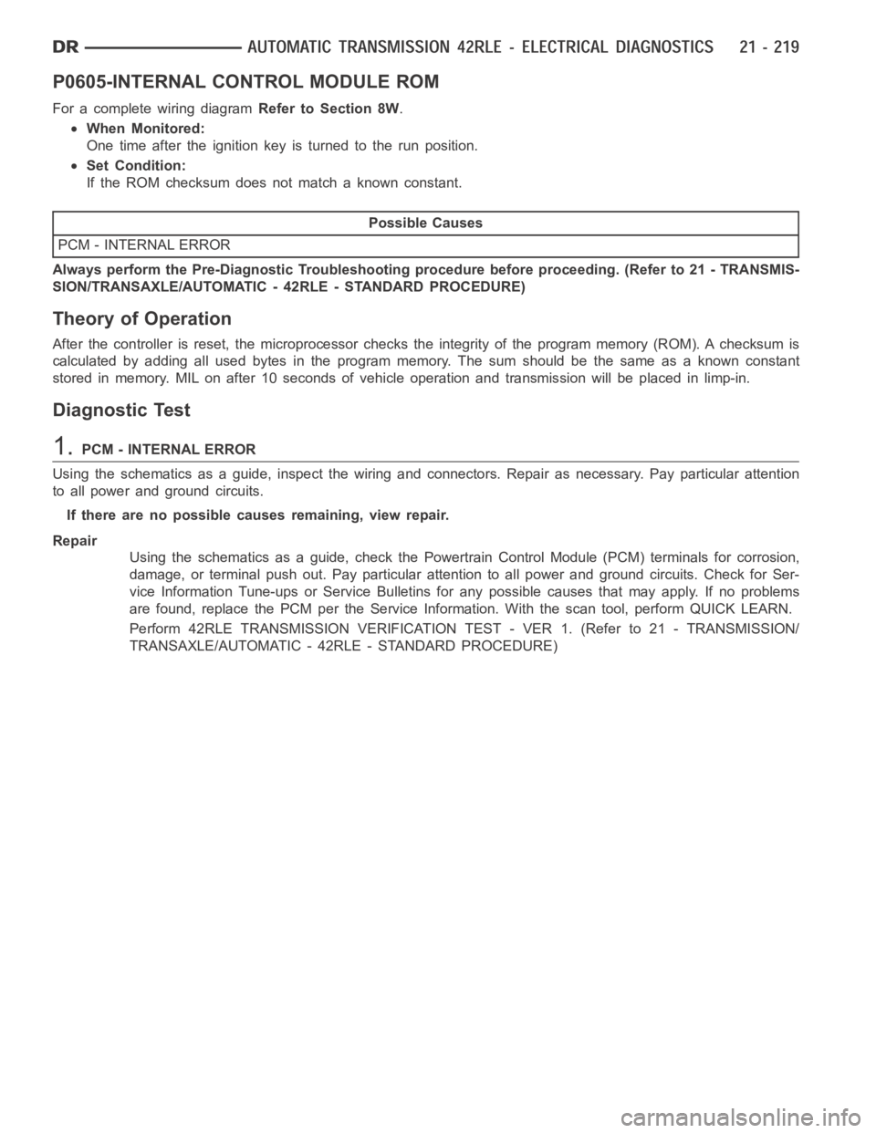
P0605-INTERNAL CONTROL MODULE ROM
For a complete wiring diagramRefer to Section 8W.
When Monitored:
One time after the ignition key is turned to the run position.
Set Condition:
If the ROM checksum does not match a known constant.
Possible Causes
PCM - INTERNAL ERROR
Always perform the Pre-Diagnostic Troubleshooting procedure before proceeding. (Refer to 21 - TRANSMIS-
SION/TRANSAXLE/AUTOMATIC - 42RLE - STANDARD PROCEDURE)
Theory of Operation
After the controller is reset, the microprocessor checksthe integrity ofthe program memory (ROM). A checksum is
calculated by adding all used bytes in the program memory. The sum should bethesameasaknownconstant
stored in memory. MIL on after 10 seconds of vehicle operation and transmission will be placed in limp-in.
Diagnostic Test
1.PCM - INTERNAL ERROR
Using the schematics as a guide, inspect the wiring and connectors. Repairas necessary. Pay particular attention
to all power and ground circuits.
If there are no possible causes remaining, view repair.
Repair
Using the schematics as a guide, check the Powertrain Control Module (PCM)terminals for corrosion,
damage, or terminal push out. Pay particular attention to all power and ground circuits. Check for Ser-
vice Information Tune-ups or Service Bulletins for any possible causes that may apply. If no problems
are found, replace the PCM per the Service Information. With the scan tool,perform QUICK LEARN.
Perform 42RLE TRANSMISSION VERIFICATION TEST - VER 1. (Refer to 21 - TRANSMISSION/
TRANSAXLE/AUTOMATIC - 42RLE - STANDARD PROCEDURE)
Page 2745 of 5267
4.TRS SENSE CIRCUIT SHORT TO GROUND
Measure the resistance between ground and the identified (T1, T3, T41, or T42) TRS Sense circuit.
Is the resistance below 5.0 ohms?
Ye s>>
Repair the identified (T1, T3, T41, or T42) TRS Sense circuit for a short to ground.
Perform the PRNDL Fault Clearing Procedure – Go To 7
No>>
Go To 5
5.TRS SENSE CIRCUIT SHORT TO OTHER CIRCUITS
Measure the resistance between the identified (T1, T3, T41, or T42) TRS Sense circuit and all other circuits in the
Transmission Solenoid/TRS Assembly harness connector.
Is the resistance below 100k ohms between the identified (T1, T3, T41, or T42) TRS Sense circuit and
any other circuit(s) in the Transmission Solenoid/TRS Assembly harness connector?
Ye s>>
Repair the identified (T1, T3, T41, or T42) TRS Sense circuit for a short to other circuit(s).
Perform the PRNDL Fault Clearing Procedure – Go To 7
No>>
Using the schematics as a guide, check the Powertrain Control Module (PCM)terminals for corrosion,
damage, or terminal push out. Pay particular attention to all power and ground circuits. If no problems
are found, replace the PCM per the Service Information. With the scan tool,perform QUICK LEARN.
Perform the PRNDL Fault Clearing Procedure – Go To 7
6.INTERMITTENT WIRING AND CONNECTORS
The conditions necessary to set the DTC are not present at this time.
Using the schematics as a guide, inspect the wiring and connectors specifictothiscircuit.
Wiggle the wiring and connectors while checking for shorted and open circuits.
With the scan tool, check the DTC EVENT DATA to help identify the conditionsin which the DTC was set.
Were there any problems found?
Ye s>>
Repair as necessary.
Perform the PRNDL Fault Clearing Procedure – Go To 7
No>>
Te s t C o m p l e t e .
7.PRNDL FAULT CLEARING PROCEDURE
With the scan tool, erase Transmission DTCs.
Cycle the ignition off, then start the vehicle.
Firmly apply the brakes and shift into Overdrive.
NOTE: Vehicle must remain in Overdrive for at least 3.0 seconds.
With the brakes firmly applied, shift slowly through all gears (PRNDL) as least three times, pausing momentarily in
each gear.
NOTE: If all the PRNDL lights box individually then the error was cleared.
Shift into park and turn the ignition off to the lock position.
Ignition on, engine not running.
With the scan tool, read Transmission DTCs.
Does the DTC P0706 reset, or do all the PRNDL indicators remain boxed in parkor neutral?
Ye s>>
Return to the symptom list and perform diagnostics for P0706-TRANSMISSION RANGE SENSOR
RATIONALITY.
Go To 1
No>>
Te s t C o m p l e t e .
Perform 42RLE TRANSMISSION VERIFICATION TEST - VER 1. (Refer to 21 - TRANSMISSION/
TRANSAXLE/AUTOMATIC - 42RLE - STANDARD PROCEDURE)
Page 2850 of 5267
P0897-TRANSMISSION FLUID DETERIORATED
For a complete wiring diagramRefer to Section 8W.
When Monitored:
Each transition from full EMCC to partial EMCC for A/C bump prevention.
Set Condition:
DTC set if 20 occurrences of a turbine acceleration sum. Fault Set Time: 20 transitions from full EMCC to
partial EMCC. Transmission will not use partial EMCC. Established for A/Cbump prevention.
Possible Causes
WORN OUT/ BURNT TRANSAXLE FLUID
Always perform the 42RLE Pre-Diagnostic Troubleshooting procedure before proceeding. (Refer to 21 -
TRANSMISSION/TRANSAXLE/AUTOMATIC - 42RLE - STANDARD PROCEDURE)
Theory of Operation
To prevent a bump due to A/C clutch engagement, a temporary torque converter partial EMCC condition is estab-
lished prior to A/C clutch engagement. A message is received over the bus indicating that A/C clutch engagement
is imminent. Partial EMCC is then established and a reply message,
OK to engage A/C clutchis sent via the bus.
Partial EMCC will be held for 450 ms before returning to full EMCC. During the transition from full to partial EMCC,
a turbine acceleration sum is calculated, if this value exceeds a threshold value for several transitions, degraded
transmission fluid is indicated.
Diagnostic Test
1.WORN OUT/ BURNT TRANSMISSION FLUID
Turn the ignition off to the lock position.
Flush the Transmission Oil Cooler and lines, replace the Transmission OilFilter, refill with new Transmission Fluid,
start the engine, and adjust the fluid per the Service Information.
NOTE: The Transmission Cooler must be flushed before proceeding.
Allow the engine to idle for 10 minutes, in Park.
Turn the ignition off to the lock position.
Again, flush the Transmission Oil Cooler and lines, replace the Transmission Oil Filter, refill with new Transmission
Fluid, start the engine, and adjust the fluid per the Service Information.
With the scan tool, perform a Battery Disconnect.
NOTE: The Battery Disconnect must be done to re-enable EMCC during an A/C Clutch engagement.
NOTE: The vehicle may exhibit intermittent shudder during the first few hundred miles. The new Transmis-
sion Fluid will gradually penetrate the Torque Convertor Clutch frictionmaterial and the shudder should
disappear.
Erase the DTC and return the vehicle to the customer.
Did the DTC reset and/or does the vehicle still shudder after a few thousandmiles?
Ye s>>
Replace the Torque Converter per the Service Information.
Perform 42RLE TRANSMISSION VERIFICATION TEST - VER 1. (Refer to 21 - TRANSMISSION/
TRANSAXLE/AUTOMATIC - 42RLE - STANDARD PROCEDURE)
No>>
Te s t C o m p l e t e .
Page 2869 of 5267
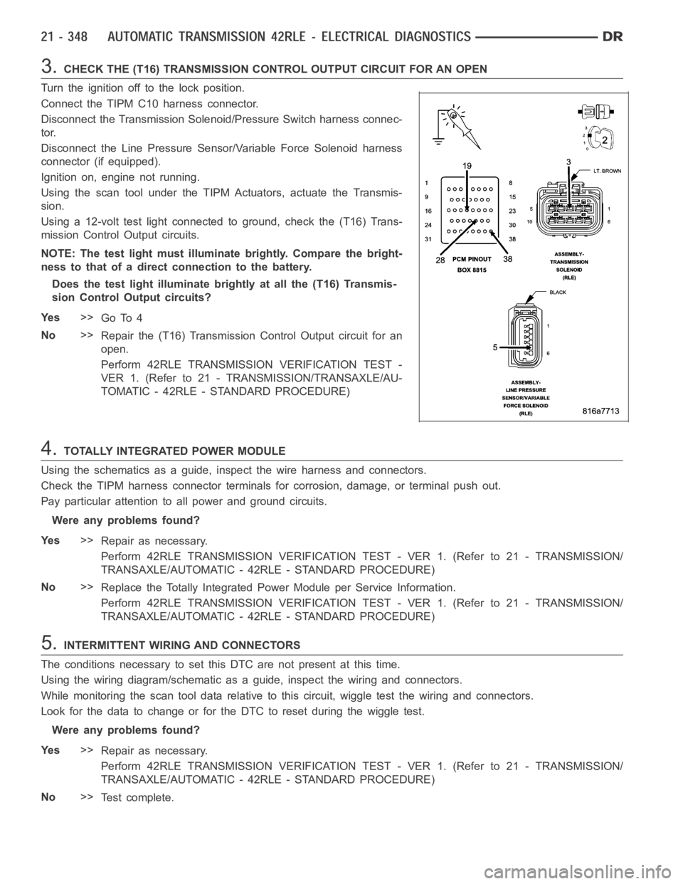
3.CHECK THE (T16) TRANSMISSION CONTROL OUTPUT CIRCUIT FOR AN OPEN
Turn the ignition off to the lock position.
Connect the TIPM C10 harness connector.
Disconnect the Transmission Solenoid/Pressure Switch harness connec-
tor.
Disconnect the Line Pressure Sensor/Variable Force Solenoid harness
connector (if equipped).
Ignition on, engine not running.
Using the scan tool under the TIPM Actuators, actuate the Transmis-
sion.
Using a 12-volt test light connected to ground, check the (T16) Trans-
mission Control Output circuits.
NOTE: The test light must illuminate brightly. Compare the bright-
ness to that of a direct connection to the battery.
Does the test light illuminate brightly at all the (T16) Transmis-
sion Control Output circuits?
Ye s>>
Go To 4
No>>
Repair the (T16) Transmission Control Output circuit for an
open.
Perform 42RLE TRANSMISSION VERIFICATION TEST -
VER 1. (Refer to 21 - TRANSMISSION/TRANSAXLE/AU-
TOMATIC - 42RLE - STANDARD PROCEDURE)
4.TOTALLY INTEGRATED POWER MODULE
Using the schematics as a guide, inspect the wire harness and connectors.
Check the TIPM harness connector terminals for corrosion, damage, or terminal push out.
Pay particular attention to all power and ground circuits.
Were any problems found?
Ye s>>
Repair as necessary.
Perform 42RLE TRANSMISSION VERIFICATION TEST - VER 1. (Refer to 21 - TRANSMISSION/
TRANSAXLE/AUTOMATIC - 42RLE - STANDARD PROCEDURE)
No>>
Replace the Totally Integrated Power Module per Service Information.
Perform 42RLE TRANSMISSION VERIFICATION TEST - VER 1. (Refer to 21 - TRANSMISSION/
TRANSAXLE/AUTOMATIC - 42RLE - STANDARD PROCEDURE)
5.INTERMITTENT WIRING AND CONNECTORS
The conditions necessary to set this DTC are not present at this time.
Using the wiring diagram/schematic as a guide, inspect the wiring and connectors.
While monitoring the scan tool data relative to this circuit, wiggle test the wiring and connectors.
Look for the data to change or for the DTC to reset during the wiggle test.
Were any problems found?
Ye s>>
Repair as necessary.
Perform 42RLE TRANSMISSION VERIFICATION TEST - VER 1. (Refer to 21 - TRANSMISSION/
TRANSAXLE/AUTOMATIC - 42RLE - STANDARD PROCEDURE)
No>>
Te s t c o m p l e t e .
Page 2872 of 5267
3.TOTALLY INTEGRATED POWER MODULE
Using the schematics as a guide, inspect the wire harness and connectors.
Check the TIPM harness connector terminals for corrosion, damage, or terminal push out
Pay particular attention to all power and ground circuits.
Were any problems found?
Ye s>>
Repair as necessary.
Perform 42RLE TRANSMISSION VERIFICATION TEST - VER 1. (Refer to 21 - TRANSMISSION/
TRANSAXLE/AUTOMATIC - 42RLE - STANDARD PROCEDURE)
No>>
Replace the Totally Integrated Power Module per Service Information.
Perform 42RLE TRANSMISSION VERIFICATION TEST - VER 1. (Refer to 21 - TRANSMISSION/
TRANSAXLE/AUTOMATIC - 42RLE - STANDARD PROCEDURE)
4.INTERMITTENT WIRING AND CONNECTORS
The conditions necessary to set this DTC are not present at this time.
Using the wiring diagram/schematic as a guide, inspect the wiring and connectors.
While monitoring the scan tool data relative to this circuit, wiggle test the wiring and connectors.
Look for the data to change or for the DTC to reset during the wiggle test.
Were any problems found?
Ye s>>
Repair as necessary.
Perform 42RLE TRANSMISSION VERIFICATION TEST - VER 1. (Refer to 21 - TRANSMISSION/
TRANSAXLE/AUTOMATIC - 42RLE - STANDARD PROCEDURE)
No>>
Te s t c o m p l e t e .