2006 DODGE RAM SRT-10 service reset
[x] Cancel search: service resetPage 465 of 5267

POWERTRAIN VERIFICATION TEST VER - 5 (DIESEL)
Diagnostic Test
1.POWERTRAIN VERIFICATION TEST VER - 5 (DIESEL)
1. Check if any of the following conditions exist.
2. The ECM has been disconnected or replace.
3. The Battery power has been disconnected.
4. Inspect the vehicle to ensure that all engine components are properly installed and connected. Reassemble and
reconnect components as necessary.
5. If any existing diagnostic trouble codes have not been repaired, go to Symptom List and follow path specified.
6. Connect the scan tool to the data link connector.
7. Ensure the fuel tank has at least a quarter tank of fuel. Turn off all accessories.
8. Perform steps 15 through 17 if the PCM has been replaced. Then proceed with the verification. If the ECM has
not been replaced skip those steps and continue verification.
9. If ECM has been changed and correct VIN and mileage have not been programmed, a DTC will be set in ABS
and Air bag modules. In addition, if vehicle is equipped with a Sentry Key Immobilizer Module (SKIM), Secret Key
data must be updated to enable start.
10. For ABS and Air Bag systems: Enter correct VIN and Mileage in ECM. Erase codes in ABS and Air Bag mod-
ules.
11. For SKIM theft alarm: Connect scan tool to data link connector to Theft Alarm, SKIM, Misc. and place SKIM in
secured access mode by using appropriate PIN code for this vehicle. SelectUpdate the Secret Key data. Data will
be transferred from SKIM to PCM.
12. If a Comprehensive Component DTC was repaired, perform steps 10-13. Ifa Major OBDII Monitor DTC was
repaired skip those steps and continue verification.
13. After the ignition has been off for at least 10 seconds, restart the vehicle and run 2 minutes.
14. If there are no new DTC’s, the repair was successful and is now complete.Erase DTC’s and disconnect the
scan tool.
15. If the repaired DTC has reset, the repair is not complete. Check for any related TSB’s or flash updates and
return to the Symptom list.
16. If another DTC has set, return to the Symptom List and follow the path specified for that DTC.
17. With the scan tool, monitor the appropriate pre-test enabling conditions until all conditions have been met. Once
the conditions have been met, switch screen to the appropriate OBDII monitor, (Audible beeps when the monitor is
running).
18. If the monitor ran, the repair was successful and is now complete. EraseDTC’s and disconnect the scan tool.
19. If the repaired OBDII trouble code has reset or was seen in the monitor while on the road test, the repair is not
complete. Check for any related technical service bulletins or flash updates and return to Symptom List.
20. If another DTC has set, return to the Symptom List and follow the path specified for that DTC.
Is any DTC(s) present?
Ye s>>
Repair is not complete, refer to appropriate symptom.
No>>
Repair is complete.
Page 678 of 5267
4.VIN PROGRAMMED INTO ECM
With the scan tool, display the VIN that is programmed in the ECM.
Has a VIN been programmed into the ECM?
Ye s>>
Go To 5
No>>
Program the correct VIN into the ECM and retest.
Perform SKIM VERIFICATION. (Refer to 8 - ELECTRICAL/VEHICLE THEFT SECURITY - STANDARD
PROCEDURE)
5.ECM
Turn the ignition off.
Replace and program the SKIM per Service Information.
Ignition on, engine not running.
With the scan tool, erase all SKIM and ECM DTCs.
Attempt to start and idle the engine.
With the scan tool, read the ECM DTCs.
Does the scan tool display this code?
Ye s>>
NOTE: Before continuing, check the ECM harness connector terminals for corrosion, damage, or termi-
nal push out. Repair as necessary. Replace and program the Engine Control Module per Service Infor-
mation.
Perform SKIM VERIFICATION. (Refer to 8 - ELECTRICAL/VEHICLE THEFT SECURITY - STANDARD
PROCEDURE)
No>>
Te s t C o m p l e t e .
6.IGNITION KEY
NOTE: You must obtain the SKIM pin number.
NOTE: This DTC could have been set if the SKIM harness connector was disconnected, or if the SKIM was
replaced recently.
NOTE: All keys that the customer uses for this vehicle must be tested to verify they are operating properly.
Ignition on, engine not running.
Verify the correct VIN is programmed into the ECM and SKIM.
Turn the ignition off.
With each customer key turn the ignition on and crank the engine to start.
With the scan tool, read the ECM DTCs. Look for P0513.
Is the DTC P0513 still active?
Ye s>>
Replace the Ignition Key.
Perform SKIM VERIFICATION. (Refer to 8 - ELECTRICAL/VEHICLE THEFT SECURITY - STANDARD
PROCEDURE)
No>>
Te s t C o m p l e t e .
NOTE: If this DTC cannot be reset, it could have been an actual theft attempt.
Page 1366 of 5267
4.STARTER
Reconnect the Starter Solenoid harness connector.
Using a 12-volt test light connected ground, probe the (T750) Stater RelayOutput circuit in the Starter Relay har-
ness connector.
Crank the engine.
Does the test light illuminate?
Ye s>>
Replace the Starter in accordance with the Service information
Perform the POWERTRAIN VERIFICATION TEST. (Refer to 9 - ENGINE - STANDARD PROCEDURE)
No>>
Go To 5
5.STARTER RELAY INTERNAL SHORT
Install a substitute relay inplaceoftheStarterRelay.
Reconnect the C9 TIPM harness connector.
Crank the engine.
With a scan tool, read DTCs.
Does the DTC reset?
Ye s>>
Replace the TIPM in accordance with the Service Information.
Perform the POWERTRAIN VERIFICATION TEST. (Refer to 9 - ENGINE - STANDARD PROCEDURE)
No>>
Replace the Starter Relay.
Perform the POWERTRAIN VERIFICATION TEST. (Refer to 9 - ENGINE - STANDARD PROCEDURE)
Page 1372 of 5267
4.(T40) STARTER RELAY OUTPUT CIRCUIT SHORTED TO GROUND
Disconnect the C9 TIPM harness connector.
Measure the resistance between ground and the (T40) Starter Relay Output circuit at the C9 TIPM harness con-
nector.
Istheresistancebelow100ohms?
Ye s>>
Repair the short to ground in the (T40) Starter Relay Output circuit.
Perform the POWERTRAIN VERIFICATION TEST. (Refer to 9 - ENGINE - STANDARD PROCEDURE)
No>>
Go To 5
5.(T40) STARTER RELAY OUTPUT CIRCUIT EXCESSIVE RESISTANCE
Measure the resistance of the (T40) Starter Relay Output circuit from the Starter Relay terminal to the C9 TIPM
harness connector.
Is the resistance above 5.0 ohms?
Ye s>>
Repair the excessive resistance in the (T40) Starter Relay Feed circuit.
Perform the POWERTRAIN VERIFICATION TEST. (Refer to 9 - ENGINE - STANDARD PROCEDURE)
No>>
Go To 6
6.STARTER RELAY
Install a known good Relay.
Ignition on, engine not running.
Clear the TIPM DTCs.
Attempt to start the engine.
Does the P127A reset?
Ye s>>
Go To 7
No>>
Replace the Starter Relay.
Perform the POWERTRAIN VERIFICATION TEST. (Refer to 9 - ENGINE - STANDARD PROCEDURE)
7.TOTALLY INTEGRATED POWER MODULE
NOTE: Before continuing, check the TIPM harness connector terminals for corrosion, damage, or terminal
push out. Repair as necessary.
Using the schematics as a guide, inspect the wire harness and connectors.
Pay particular attention to all Power and Ground circuits.
Were any problems found?
Ye s>>
Repair as necessary.
Perform the POWERTRAIN VERIFICATION TEST. (Refer to 9 - ENGINE - STANDARD PROCEDURE)
No>>
Replace the Totally Integrated Power Module per Service Information.
Perform the BODY VERIFICATION TEST – VER 1. (Refer to 8 - ELECTRICAL/ELECTRONIC CON-
TROL MODULES - STANDARD PROCEDURE)
Page 1413 of 5267
P1398-MIS-FIRE ADAPTIVE NUMERATOR AT LIMIT
For a complete wiring diagramRefer to Section 8W.
When Monitored:
Under closed throttle decel and Fuel Pulse Width equal to zero for 30 seconds.
Set Condition:
One of the CKP sensor target windows has more than 2.86% variance from the reference window.
Possible Causes
ADAPTIVE NUMERATOR RELEARN
CMP SENSOR CONNECTOR/WIRING
CKP SENSOR CONNECTOR/WIRING
DAMAGED TONE WHEEL/FLEX PLATE (CRANKSHAFT)
CRANKSHAFT POSITION SENSOR
PCM
Always perform the Pre-Diagnostic Troubleshooting procedure before proceeding. (Refer to 9 - ENGINE -
DIAGNOSIS AND TESTING)
1.ADAPTIVE NUMERATOR RELEARN
NOTE: Check for any TSB’s that may apply to this symptom.
Read and record the Freeze Frame Data. Use this information to help you duplicate the conditions that set the DTC.
Pay particular attention to the DTC set conditions, such as, VSS, MAP, ECT,and Load.
Ignition on, engine not running.
With the scan tool in the miscellaneous menu, choose Clear PCM (battery disconnect) to reset the PCM.
With the scan tool, choose the Misfire Pretest screen.
Road test the vehicle and re-learn the adaptive numerator.
The adaptive numerator is learned when the Adaptive Numerator Done Learning line on the Misfire screen changes
to Yes.
Did the adaptive numerator re-learn?
Ye s>>
Refer to the INTERMITTENT CONDITIONSymptom (Diagnostic Procedure).
Perform POWERTRAIN VERIFICATION TEST. (Refer to 9 - ENGINE - STANDARD PROCEDURE)
No>>
Go To 2
2.CMP CONNECTOR/HARNESS INSPECTION
Turn ignition off.
NOTE: Visually inspect the related wire harness connectors. Look for broken, bent, pushed out, or corroded
terminals.
NOTE: Visually inspect the related wire harness. Look for any chafed, pierced, pinched, or partially broken
wires.
NOTE: Make sure the Camshaft Position Sensor is tight.
NOTE: Refer to any technical service bulletins that may apply.
Were any problems found?
Ye s>>
Repair as necessary.
Perform POWERTRAIN VERIFICATION TEST. (Refer to 9 - ENGINE - STANDARD PROCEDURE)
No>>
Go To 3
Page 1456 of 5267
When Monitored:
With the ignition on.
Set Condition:
The PCM has not received an expected Cluster Status Bus message from the instrument cluster within the last
20 seconds.
Possible Causes
(D25) OPEN BETWEEN PCM AND CLUSTER
(D25) SHORTED BETWEEN PCM AND CLUSTER
CLUSTER
PCM
Always perform the Pre-Diagnostic Troubleshooting procedure before proceeding. (Refer to 9 - ENGINE -
DIAGNOSIS AND TESTING)
Diagnostic Test
1.NO CLUSTER BUS MESSAGE
Ignition on, engine not running.
With the scan tool, erase DTCs.
Cycle the ignition key on and off several times.
With the scan tool, read DTCs.
Does the DTC reset?
Ye s>>
Go To 2
No>>
Refer to the INTERMITTENT CONDITION Diagnostic Procedure.
Perform the POWERTRAIN VERIFICATION TEST. (Refer to 9 - ENGINE - STANDARD PROCEDURE)
2.COMMUNICATE WITH CLUSTER
Ignition on, engine not running.
With the scan tool, attempt to communicate with the Instrument cluster.
Can communication be established with the Instrument Cluster?
Ye s>>
Go To 3
No>>
Refer to the Communication Category of the Body Diagnostic Manual and perform the appropriate
symptom related to no communication with cluster.
Perform the POWERTRAIN VERIFICATION TEST. (Refer to 9 - ENGINE - STANDARD PROCEDURE)
3.INSTRUMENT CLUSTER OPERATION
Start the engine
Allow the engine to idle.
Is the correct engine speed display in the instrument cluster (Tach)?
Ye s>>
Replace and program the Powertrain Control Module per Service Information.
Perform the POWERTRAIN VERIFICATION TEST. (Refer to 9 - ENGINE - STANDARD PROCEDURE)
No>>
Refer to the Instrument Category in the Body Diagnostic Manual and performthe appropriate symptom.
Perform the POWERTRAIN VERIFICATION TEST. (Refer to 9 - ENGINE - STANDARD PROCEDURE)
Page 1485 of 5267
NOTE: If this vehicle is equipped with an Electronic Throttle Control system, and the APP Sensors, PCM, or
Throttle Body Assembly have been replaced, use the scan tool to perform theETC RELEARN function.
14. If the indicator ball shows a leak present, perform the smoke test indicated in the previous test and identify the
leak and repair. Perform this verification test when the repair is complete.
Didtheindicatorballindicatethealeakispresent?
Ye s>>
Repeat the DTC test to identify the leak and repair.
No>>
Repair is complete.
5.POWERTRAIN VERIFICATION TEST 4
NOTE: 1. After completing the Powertrain Verification Test the Transmission Verification Test must be per-
formed.
NOTE: 2. If the PCM has been replaced and the correct VIN and mileage have notbeen programmed, a DTC
will set in the ABS Module, Airbag Module and the SKIM/SKREEM.
NOTE: 3. If the vehicle is equipped with a Sentry Key Remote Entry, Secret Key data must be updated. Refer
to the Service Information for the PCM, SKIM/SKREEM and the Transponder (ignition key) for programming
information. Using the scan tool, program the Secret Key information intothe PCM using the PCM replaced
function under the WCM menu.
NOTE: 4. If this vehicle is equipped with an Electronic Throttle Control system, and the APP Sensors, PCM,
or Throttle Body Assembly have been replaced, use the scan tool to perform the ETC RELEARN function.
NOTE: 5. When replacing an O2 Sensor, the PCM RAM memory must be cleared, either by disconnecting the
PCM C1 connector or momentarily disconnecting the Battery negative terminal.
6. The NGC learns the characteristics of each O2 heater element and these old values should be cleared when
installing a new O2 sensor. The customermay experience driveability issues if this is not performed.
7. Inspect the vehicle to make sure that all engine components are properlyinstalled and connected. Reassemble
and reconnect components as necessary.
8. Connect the scan tool to the data link connector.
9. Make sure the fuel tank has at least a quarter tank of fuel. Turn off all accessories.
10. If the Catalyst was replaced, with the scan tool go to the MiscellaneousMenu Option
Catalyst Replacedand
press enter.
11. If a Comprehensive Component DTC was repaired, perform steps 12 - 14. Ifa Major OBDII Monitor DTC was
repaired skip those steps and continue verification.
12. After the ignition has been off for at least 10 seconds, restart the vehicle and run 2 minutes.
13. With the scan tool, monitor the appropriate pre-test enabling conditions until all conditions have been met. Once
the conditions have been met, switch screen to the appropriate OBDII monitor, (Audible beeps when the monitor is
running).
14. If the repaired OBDII trouble code has reset or was seen in the monitor while on the road test, the repair is not
complete. Check for any related technical service bulletins or flash updates and return to Engine Electrical Diag-
nostic List.
15. If the conditions cannot be duplicated, erase all DTCs with the Scan tool.
16. If another DTC has set, return to the Engine Electrical Diagnostic Listand follow the path specified for that DTC.
Did the OBDII Monitor run successfully and has the Good Trip Counter changed to one or more?
Ye s>>
Repair is complete.
No>>
Check for any related Technical Service Bulletins and/or refer to the appropriate Diagnostic Procedure.
Page 1953 of 5267
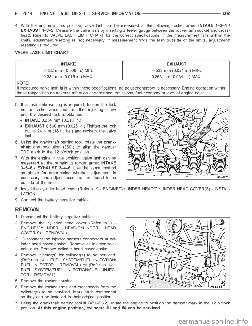
4. With the engine in this position, valve lash can be measured at the following rocker arms:INTAKE 1–2–4 /
EXHAUST 1–3–5. Measure the valve lash by inserting a feeler gauge between the rocker arm socket and cross-
head. Refer to VALVE LASH LIMIT CHART for the correct specifications. If the measurement fallswithinthe
limits, adjustment/resettingis notnecessary. If measurement finds the lashoutsideof the limits, adjustment/
resettingisrequired.
VALVE LASH LIMIT CHART
INTAKE EXHAUST
0.152 mm ( 0.006 in.) MIN. 0.533 mm (0.021 in.) MIN.
0.381 mm (0.015 in.) MAX. 0.863 mm (0.034 in.) MAX.
NOTE:
If measured valve lash falls within these specifications, no adjustment/reset is necessary. Engine operation within
these ranges has no adverse affect on performance, emissions, fuel economy or level of engine noise.
5. If adjustment/resetting is required, loosen the lock
nut on rocker arms and turn the adjusting screw
until the desired lash is obtained:
INTAKE0.254 mm (0.010 in.)
EXHAUST0.660 mm (0.026 in.) Tighten the lock
nut to 24 Nꞏm (18 ft. lbs.) and recheck the valve
lash.
6. Using the crankshaft barring tool, rotate thecrank-
shaftone revolution (360°) to align the damper
TDC mark to the 12 o’clock position.
7. With the engine in this position, valve lash can be
measured at the remaining rocker arms:INTAKE
3–5–6 / EXHAUST 2–4–6. Use the same method
as above for determining whether adjustment is
necessary, and adjust those that are found to be
outside of the limits.
8. Install the cylinder head cover (Refer to 9 - ENGINE/CYLINDER HEAD/CYLINDER HEAD COVER(S) - INSTAL-
LATION).
9. Connect the battery negative cables.
REMOVAL
1. Disconnect the battery negative cables.
2. Remove the cylinder head cover (Refer to 9 -
ENGINE/CYLINDER HEAD/CYLINDER HEAD
COVER(S) - REMOVAL).
3. Disconnect the injector harness connectors at cyl-
inder head cover gasket. Remove all injector sole-
noid nuts. Remove cylinder head cover gasket.
4. Remove injector(s) for cylinder(s) to be serviced.
(Refer to 14 - FUEL SYSTEM/FUEL INJECTION/
FUELINJECTOR-REMOVAL)or(Referto14-
FUEL SYSTEM/FUEL INJECTION/FUEL INJEC-
TOR - REMOVAL).
5. Remove the rocker housing.
6. Remove the rocker arms and crossheads from the
cylinder(s) to be serviced. Mark each component
so they can be installed in their original position.
7. Using the crankshaft barring tool # 7471–B (2), rotate the engine to position the damper mark in the 12 o’clock
position.At this engine position, cylinders #1 and #6 can be serviced.