Page 4338 of 5267
BODY
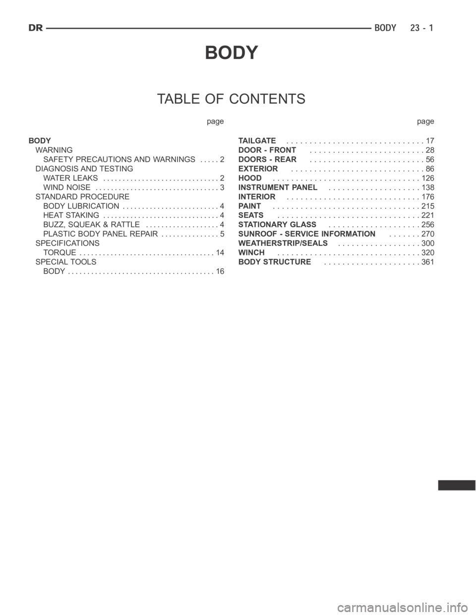
TABLE OF CONTENTS
page page
BODY
WARNING
SAFETY PRECAUTIONS AND WARNINGS ..... 2
DIAGNOSIS AND TESTING
WATER LEAKS .............................. 2
WIND NOISE ................................ 3
STANDARD PROCEDURE
BODY LUBRICATION ......................... 4
HEAT STAKING .............................. 4
BUZZ, SQUEAK & RATTLE ................... 4
PLASTIC BODY PANEL REPAIR ............... 5
SPECIFICATIONS
TORQUE ................................... 14
SPECIAL TOOLS
BODY ...................................... 16TA I L G AT E..............................17
DOOR - FRONT.........................28
DOORS - REAR.........................56
EXTERIOR.............................86
HOOD................................126
INSTRUMENT PANEL....................138
INTERIOR.............................176
PA I N T................................215
SEATS...............................221
STATIONARY GLASS....................256
SUNROOF - SERVICE INFORMATION.......270
WEATHERSTRIP/SEALS..................300
WINCH...............................320
BODY STRUCTURE.....................361
Page 4343 of 5267
Rigid Plastics:
Examples of rigid plastic use: Fascias, Hoods, Doors, and other Body Panels, which include SMC, ABS, and Poly-
carbonates.
Semi-Rigid Plastics:
Examples of semi-rigid plastic use: Interior Panels, Under Hood Panels, and other Body Trim Panels.
Flexible Plastics:
Examples of flexible plastic use: Fascias, Body Moldings, and upper and lower Fascia Covers.
Repair Procedure:
The repair procedure for all three categories of plastics is basically thesame. The one difference is the material
used for the repair. The materials must be specific for each substrate, rigid repair material for rigid plastic repair,
semi-rigid repair material for semi-rigid plastic repair and flexible repair material for flexible plastic repair.
Adhesion Promoter/Surface Modifier:
Adhesion Promoters/Surface Modifiers are required for certain plastics. All three categories may have plastics that
require the use of adhesion promoter/surface modifiers. Always follow repair material manufacturer’s plastic identi-
fication and repair procedures.
SAFETY PRECAUTION AND WARNINGS
WARNING:
Eye protection should be used when servicing components. Personal injurycan result.
Use an OSHA approved breathing mask when mixing epoxy, grinding, and spraying paint or solvents in
a confined area. Personal injury can result.
Avoid prolonged skin contact with resin, petroleum, or alcohol based solvents. Personal injury can
result.
Do not venture under a hoisted vehicle that is not properly supported on safety stands. Personal injury
can result.
NOTE:
When holes must be drilled or cut in bodypanels, verify locations of internal body components and elec-
trical wiring. Damage to vehicle can result.
Do not use abrasive chemicals or compounds on undamaged painted surfaces around repair areas. Dam-
age to finish can result.
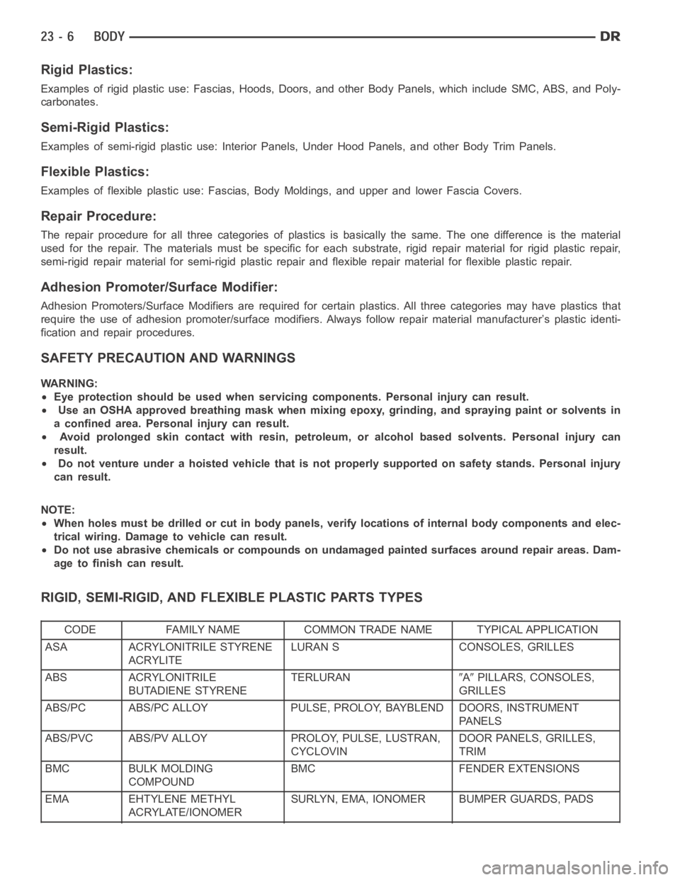
RIGID, SEMI-RIGID, AND FLEXIBLE PLASTIC PARTS TYPES
CODE FAMILY NAME COMMON TRADE NAME TYPICAL APPLICATION
ASA ACRYLONITRILE STYRENE
ACRYLITELURAN S CONSOLES, GRILLES
ABS ACRYLONITRILE
BUTADIENE STYRENETERLURAN
APILLARS, CONSOLES,
GRILLES
ABS/PC ABS/PC ALLOY PULSE, PROLOY, BAYBLEND DOORS, INSTRUMENT
PA N E L S
ABS/PVC ABS/PV ALLOY PROLOY, PULSE, LUSTRAN,
CYCLOVINDOOR PANELS, GRILLES,
TRIM
BMC BULK MOLDING
COMPOUNDBMC FENDER EXTENSIONS
EMA EHTYLENE METHYL
ACRYLATE/IONOMERSURLYN, EMA, IONOMER BUMPER GUARDS, PADS
Page 4344 of 5267
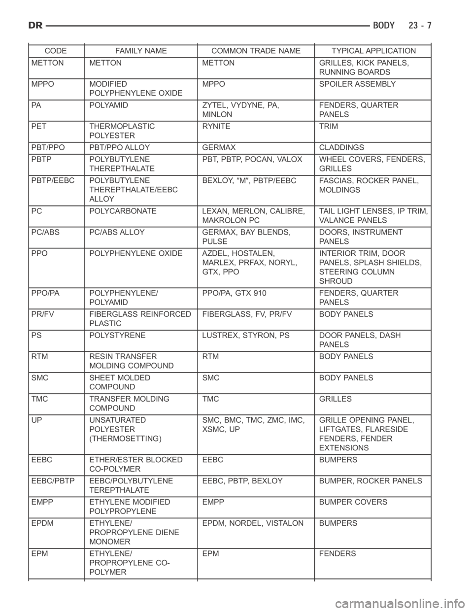
CODE FAMILY NAME COMMON TRADE NAME TYPICAL APPLICATION
METTON METTON METTON GRILLES, KICK PANELS,
RUNNING BOARDS
MPPO MODIFIED
POLYPHENYLENE OXIDEMPPO SPOILER ASSEMBLY
PA POLYAMID ZYTEL, VYDYNE, PA,
MINLONFENDERS, QUARTER
PA N E L S
PET THERMOPLASTIC
POLYESTERRYNITE TRIM
PBT/PPO PBT/PPO ALLOY GERMAX CLADDINGS
PBTP POLYBUTYLENE
THEREPTHALATEPBT, PBTP, POCAN, VALOX WHEEL COVERS, FENDERS,
GRILLES
PBTP/EEBC POLYBUTYLENE
THEREPTHALATE/EEBC
ALLOYBEXLOY,
M, PBTP/EEBC FASCIAS, ROCKER PANEL,
MOLDINGS
PC POLYCARBONATE LEXAN, MERLON, CALIBRE,
MAKROLON PCTAIL LIGHT LENSES, IP TRIM,
VA L A N C E PA N E L S
PC/ABS PC/ABS ALLOY GERMAX, BAY BLENDS,
PULSEDOORS, INSTRUMENT
PA N E L S
PPO POLYPHENYLENE OXIDE AZDEL, HOSTALEN,
MARLEX, PRFAX, NORYL,
GTX, PPOINTERIOR TRIM, DOOR
PANELS, SPLASH SHIELDS,
STEERING COLUMN
SHROUD
PPO/PA POLYPHENYLENE/
POLYAMIDPPO/PA, GTX 910 FENDERS, QUARTER
PA N E L S
PR/FV FIBERGLASS REINFORCED
PLASTICFIBERGLASS, FV, PR/FV BODY PANELS
PS POLYSTYRENE LUSTREX, STYRON, PS DOOR PANELS, DASH
PA N E L S
RTM RESIN TRANSFER
MOLDING COMPOUNDRTM BODY PANELS
SMC SHEET MOLDED
COMPOUNDSMC BODY PANELS
TMC TRANSFER MOLDING
COMPOUNDTMC GRILLES
UP UNSATURATED
POLYESTER
(THERMOSETTING)SMC, BMC, TMC, ZMC, IMC,
XSMC, UPGRILLE OPENING PANEL,
LIFTGATES, FLARESIDE
FENDERS, FENDER
EXTENSIONS
EEBC ETHER/ESTER BLOCKED
CO-POLYMEREEBC BUMPERS
EEBC/PBTP EEBC/POLYBUTYLENE
TEREPTHALATEEEBC, PBTP, BEXLOY BUMPER, ROCKER PANELS
EMPP ETHYLENE MODIFIED
POLYPROPYLENEEMPP BUMPER COVERS
EPDM ETHYLENE/
PROPROPYLENE DIENE
MONOMEREPDM, NORDEL, VISTALON BUMPERS
EPM ETHYLENE/
PROPROPYLENE CO-
POLYMEREPM FENDERS
Page 4351 of 5267
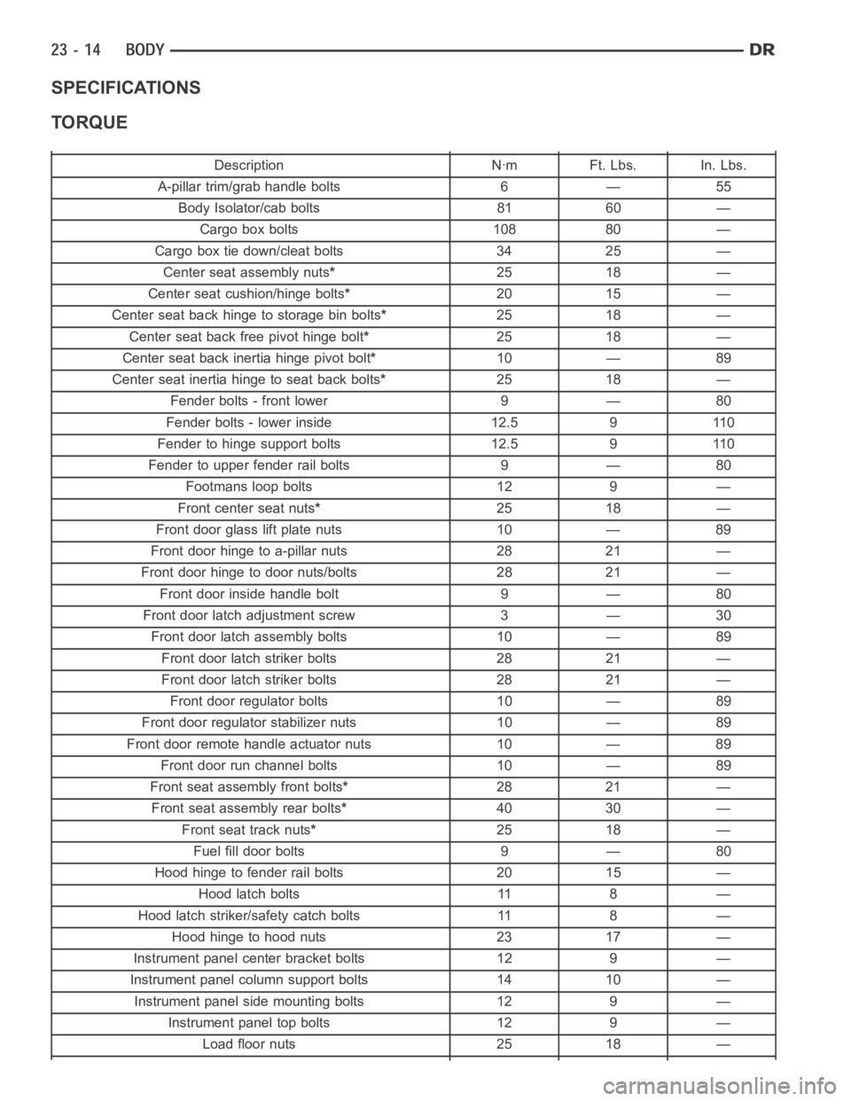
SPECIFICATIONS
TORQUE
Description Nꞏm Ft. Lbs. In. Lbs.
A-pillar trim/grab handle bolts 6 — 55
Body Isolator/cab bolts 81 60 —
Cargo box bolts 108 80 —
Cargo box tie down/cleat bolts 34 25 —
Center seat assembly nuts*25 18 —
Center seat cushion/hinge bolts*20 15 —
Center seat back hinge to storage bin bolts*25 18 —
Center seat back free pivot hinge bolt*25 18 —
Center seat back inertia hinge pivot bolt*10 — 89
Center seat inertia hinge to seat back bolts*25 18 —
Fender bolts - front lower 9 — 80
Fender bolts - lower inside 12.5 9 110
Fender to hinge support bolts 12.5 9 110
Fender to upper fender rail bolts 9 — 80
Footmans loop bolts 12 9 —
Front center seat nuts*25 18 —
Front door glass lift plate nuts 10 — 89
Front door hinge to a-pillar nuts 28 21 —
Front door hinge to door nuts/bolts 28 21 —
Front door inside handle bolt 9 — 80
Front door latch adjustment screw 3 — 30
Front door latch assembly bolts 10 — 89
Front door latch striker bolts 28 21 —
Front door latch striker bolts 28 21 —
Front door regulator bolts 10 — 89
Front door regulator stabilizer nuts 10 — 89
Front door remote handle actuator nuts 10 — 89
Front door run channel bolts 10 — 89
Front seat assembly front bolts*28 21 —
Front seat assembly rear bolts*40 30 —
Frontseattracknuts*25 18 —
Fuel fill door bolts 9 — 80
Hood hinge to fender rail bolts 20 15 —
Hood latch bolts 11 8 —
Hood latch striker/safety catch bolts 11 8 —
Hood hinge to hood nuts 23 17 —
Instrument panel center bracket bolts 12 9 —
Instrument panel column support bolts 14 10 —
Instrument panel side mounting bolts 12 9 —
Instrument panel top bolts 12 9 —
Load floor nuts 25 18 —
Page 4471 of 5267
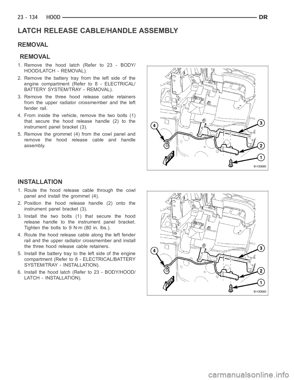
LATCH RELEASE CABLE/HANDLE ASSEMBLY
REMOVAL
REMOVAL
1.Removethehoodlatch(Referto23-BODY/
HOOD/LATCH - REMOVAL).
2. Remove the battery tray from the left side of the
engine compartment (Refer to 8 - ELECTRICAL/
BATTERY SYSTEM/TRAY - REMOVAL).
3. Remove the three hood release cable retainers
from the upper radiator crossmember and the left
fender rail.
4. From inside the vehicle, remove the two bolts (1)
that secure the hood release handle (2) to the
instrument panel bracket (3).
5. Remove the grommet (4) from the cowl panel and
remove the hood release cable and handle
assembly.
INSTALLATION
1. Route the hood release cable through the cowl
panel and install the grommet (4).
2. Position the hood release handle (2) onto the
instrument panel bracket (3).
3. Install the two bolts (1) that secure the hood
release handle to the instrument panel bracket.
Tightentheboltsto9Nꞏm(80in.lbs.).
4. Route the hood release cable along the left fender
rail and the upper radiator crossmember and install
the three hood release cable retainers.
5. Install the battery tray to the left side of the engine
compartment (Refer to 8 - ELECTRICAL/BATTERY
SYSTEM/TRAY - INSTALLATION).
6. Install the hood latch (Refer to 23 - BODY/HOOD/
LATCH - INSTALLATION).
Page 4475 of 5267
page page
CLUSTER BEZEL
REMOVAL ................................... 139
INSTALLATION .............................. 140
CUP HOLDER
REMOVAL ................................... 141
INSTALLATION .............................. 142
GLOVE BOX
REMOVAL ................................... 144
INSTALLATION .............................. 144
GLOVE BOX LATCH
REMOVAL ................................... 145
INSTALLATION .............................. 146
INSTRUMENT PANEL ASSEMBLY
REMOVAL ................................... 147
INSTALLATION .............................. 155
INSTRUMENT PANEL CENTER BEZEL
REMOVAL ................................... 164
INSTALLATION .............................. 165
INSTRUMENT PANEL DRIVER SIDE BEZEL
REMOVAL ................................... 166INSTALLATION .............................. 166
INSTRUMENT PANEL LOWER SURROUND
REMOVAL ................................... 167
INSTALLATION .............................. 167
INSTRUMENT PANEL TOP COVER
REMOVAL ................................... 169
INSTALLATION .............................. 169
STEERING COLUMN OPENING COVER
REMOVAL ................................... 170
INSTALLATION .............................. 171
STEERING COLUMN OPENING SUPPORT
BRACKET
REMOVAL ................................... 173
INSTALLATION .............................. 174
STORAGE BIN
REMOVAL ................................... 175
INSTALLATION .............................. 175
Page 4476 of 5267
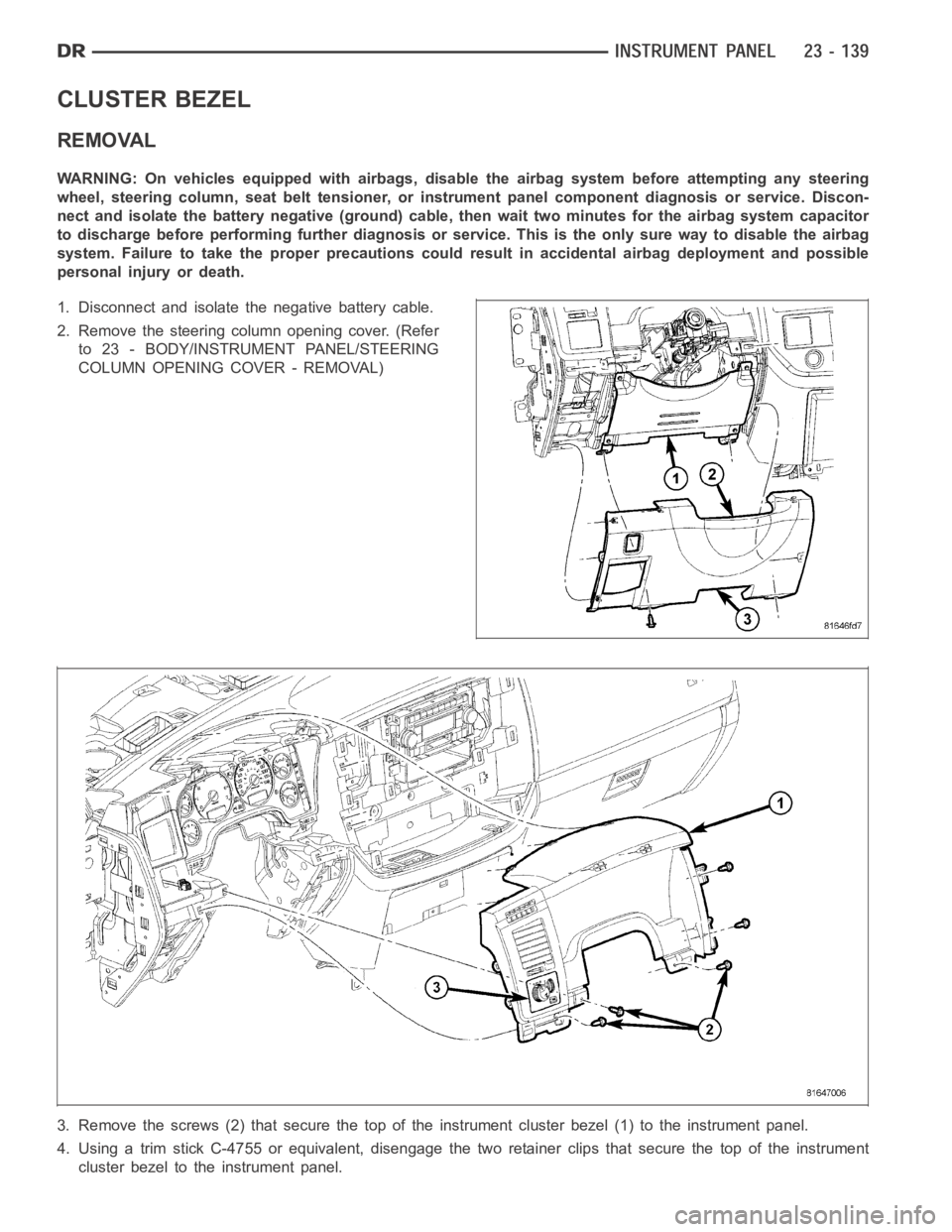
CLUSTER BEZEL
REMOVAL
WARNING: On vehicles equipped with airbags, disable the airbag system before attempting any steering
wheel, steering column, seat belt tensioner, or instrument panel component diagnosis or service. Discon-
nect and isolate the battery negative (ground) cable, then wait two minutes for the airbag system capacitor
to discharge before performing further diagnosis or service. This is the only sure way to disable the airbag
system. Failure to take the proper precautions could result in accidentalairbag deployment and possible
personal injury or death.
1. Disconnect and isolate the negative battery cable.
2. Remove the steering column opening cover. (Refer
to 23 - BODY/INSTRUMENT PANEL/STEERING
COLUMN OPENING COVER - REMOVAL)
3. Remove the screws (2) that secure the top of the instrument cluster bezel(1) to the instrument panel.
4. Using a trim stick C-4755 or equivalent, disengage the two retainer clips that secure the top of the instrument
cluster bezel to the instrument panel.
Page 4477 of 5267
5. Carefully disengage the instrument cluster bezel from the instrument panel opening and remove the bezel.
INSTALLATION
1. Install the instrument cluster bezel onto the instrument panel and fully engage the two retainer clips to the instru-
ment panel.
2. Install the screws (2) that secure the instrument cluster bezel to the instrument panel.
3. Install the steering column opening cover. (Refer to
23 - BODY/INSTRUMENT PANEL/STEERING
COLUMN OPENING COVER - INSTALLATION)
4. Connect the negative battery cable.