Page 4501 of 5267
INSTRUMENT PANEL CENTER BEZEL
REMOVAL
WARNING: On vehicles equipped with airbags, disable the airbag system before attempting any steering
wheel, steering column, seat belt tensioner, or instrument panel component diagnosis or service. Discon-
nect and isolate the battery negative (ground) cable, then wait two minutes for the airbag system capacitor
to discharge before performing further diagnosis or service. This is the only sure way to disable the airbag
system. Failure to take the proper precautions could result in accidentalairbag deployment and possible
personal injury or death.
1. Disconnect and isolate the negative battery cable.
2. Using a trim stick C-4755 or equivalent, disengage
the retainer clips that secure the instrument panel
center bezel to the instrument panel.
3. Disconnect the wire harness connectors and
remove the center bezel from the vehicle.
Page 4502 of 5267
INSTALLATION
1. Position the instrument panel center bezel (2) near
the instrument panel (1) and connect the wire har-
ness connectors.
2. Install the instrument panel center bezel onto the
instrument panel and fully engage the retainer
clips.
3. Connect the negative battery cable.
Page 4503 of 5267

INSTRUMENT PANEL DRIVER SIDE BEZEL
REMOVAL
WARNING: On vehicles equipped with airbags, disable the airbag system before attempting any steering
wheel, steering column, seat belt tensioner, or instrument panel component diagnosis or service. Discon-
nect and isolate the battery negative (ground) cable, then wait two minutes for the airbag system capacitor
to discharge before performing further diagnosis or service. This is the only sure way to disable the airbag
system. Failure to take the proper precautions could result in accidentalairbag deployment and possible
personal injury or death.
1. Disconnect and isolate the negative battery cable.
2. Using a trim stick C-4755 or equivalent, from the
notch on the bottom, remove the left instrument
panel side cover.
3. Remove the left cowl trim panel (Refer to 23 -
BODY/INTERIOR/COWL TRIM - REMOVAL).
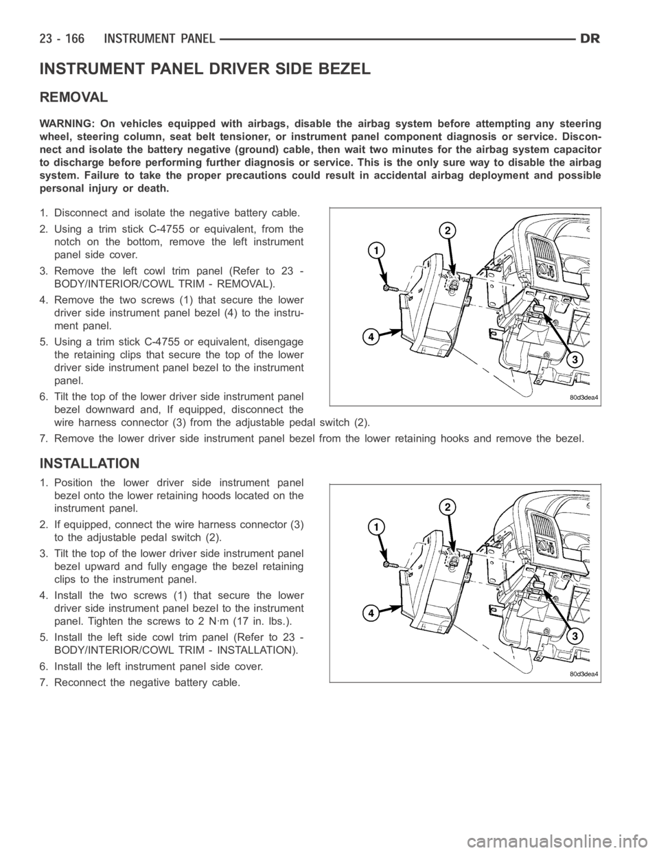
4. Remove the two screws (1) that secure the lower
driver side instrument panel bezel (4) to the instru-
ment panel.
5. Using a trim stick C-4755 or equivalent, disengage
the retaining clips that secure the top of the lower
driver side instrument panel bezel to the instrument
panel.
6. Tilt the top of the lower driver side instrument panel
bezel downward and, If equipped, disconnect the
wire harness connector (3) from the adjustable pedal switch (2).
7. Remove the lower driver side instrument panel bezel from the lower retaining hooks and remove the bezel.
INSTALLATION
1. Position the lower driver side instrument panel
bezel onto the lower retaining hoods located on the
instrument panel.
2. If equipped, connect the wire harness connector (3)
to the adjustable pedal switch (2).
3. Tilt the top of the lower driver side instrument panel
bezel upward and fully engage the bezel retaining
clips to the instrument panel.
4. Install the two screws (1) that secure the lower
driver side instrument panel bezel to the instrument
panel. Tighten the screws to 2 Nꞏm (17 in. lbs.).
5. Install the left side cowl trim panel (Refer to 23 -
BODY/INTERIOR/COWL TRIM - INSTALLATION).
6. Install the left instrument panel side cover.
7. Reconnect the negative battery cable.
Page 4504 of 5267

INSTRUMENT PANEL LOWER SURROUND
REMOVAL
WARNING: On vehicles equipped with airbags, disable the airbag system before attempting any steering
wheel, steering column, seat belt tensioner, or instrument panel component diagnosis or service. Discon-
nect and isolate the battery negative (ground) cable, then wait two minutes for the airbag system capacitor
to discharge before performing further diagnosis or service. This is the only sure way to disable the airbag
system. Failure to take the proper precautions could result in accidentalairbag deployment and possible
personal injury or death.
1. Disconnect and isolate the negative battery cable.
2. Using a trim stick C-4755 or equivalent, from the
notch on the bottom, remove the right instrument
panel side cover.
3. Remove the right side cowl trim panel (Refer to 23
- BODY/INTERIOR/COWL TRIM - REMOVAL).
4. Remove the glove box (Refer to 23 - BODY/IN-
STRUMENT PANEL/GLOVE BOX - REMOVAL).
5. Remove the cup holder or storage bin (depending
on application) (Refer to 23 - BODY/INSTRUMENT
PANEL/CUPHOLDER-REMOVAL)or(Referto23
- BODY/INSTRUMENT PANEL/STORAGE BIN -
REMOVAL).
6. Remove the ash receiver (Refer to 23 - BODY/IN-
STRUMENT PANEL/ASH RECEIVER -
REMOVAL).
7. Remove the steering column opening cover (Refer
to 23 - BODY/INSTRUMENT PANEL/STEERING
COLUMN OPENING COVER - REMOVAL).
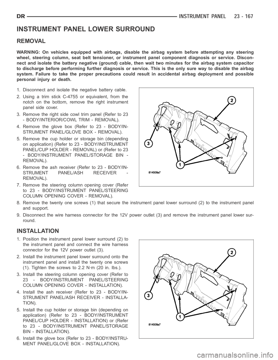
8. Remove the twenty one screws (1) that secure the instrument panel lower surround (2) to the instrument panel
and support.
9. Disconnect the wire harness connector for the 12V power outlet (3) and remove the instrument panel lower sur-
round.
INSTALLATION
1. Position the instrument panel lower surround (2) to
the instrument panel and connect the wire harness
connector for the 12V power outlet (3).
2. Install the instrument panel lower surround onto the
instrument panel and install the twenty one screws
(1). Tighten the screws to 2.2 Nꞏm (20 in. lbs.).
3. Install the steering column opening cover (Refer to
23 - BODY/INSTRUMENT PANEL/STEERING
COLUMN OPENING COVER - INSTALLATION).
4. Install the ash receiver (Refer to 23 - BODY/IN-
STRUMENT PANEL/ASH RECEIVER - INSTALLA-
TION).
5. Install the cup holder or storage bin (depending on
application) (Refer to 23 - BODY/INSTRUMENT
PANEL/CUP HOLDER - INSTALLATION) or (Refer
to 23 - BODY/INSTRUMENT PANEL/STORAGE
BIN - INSTALLATION).
6. Install the glove box (Refer to 23 - BODY/INSTRU-
MENT PANEL/GLOVE BOX - INSTALLATION).
Page 4505 of 5267
7. Install the right side cowl trim panel (Refer to 23 - BODY/INTERIOR/COWLTRIM - INSTALLATION).
8. Install the right instrument panel side cover.
9. Reconnect the negative battery cable.
Page 4506 of 5267
INSTRUMENT PANEL TOP COVER
REMOVAL
1. Using a trim stick C-4755 or equivalent, disengage
the eight retainer clips (1) that secure the rear of
the instrument panel top cover (2) to the top of the
instrument panel (3).
2. Pull the instrument panel top cover rearward to
release the five retainer clips (4) that secure the
front of the instrument panel top cover to the top of
the instrument panel and remove the cover.
INSTALLATION
1. Position the instrument panel top cover (2) to the
top of the instrument panel (3) and engage the five
retainer clips (4) that secure the cover to the instru-
ment panel.
2. Engage the eight retainer clips (1) that secure the
instrument panel top cover to the top of the instru-
ment panel by firmly pushing down on the top
cover at each retainer clip location.
Page 4507 of 5267
STEERING COLUMN OPENING COVER
REMOVAL
1. Remove the park brake release handle. (Refer to 5
- BRAKES/PARKING BRAKE/RELEASE -
REMOVAL)
2. Remove the two screws that secure the bottom of
the steering column opening cover (3) to the instru-
ment panel.
3. Using a trim stick C-4755 or equivalent, release the
two retainer clips that secure the top of the steering
column opening cover (2) to the instrument panel
and remove the cover.
Page 4509 of 5267
2. Position the steering column opening cover (2) to
the instrument panel and fully engage the two
upper retainer clips to the instrument panel.
3. Install the two screws that secure the steering col-
umn opening cover to the instrument panel.
4. Install the park brake release handle. (Refer to 5 -
BRAKES/PARKING BRAKE/RELEASE -
INSTALLATION)