2006 DODGE RAM SRT-10 instrument panel
[x] Cancel search: instrument panelPage 5121 of 5267
MOTOR-BLOWER
DESCRIPTION
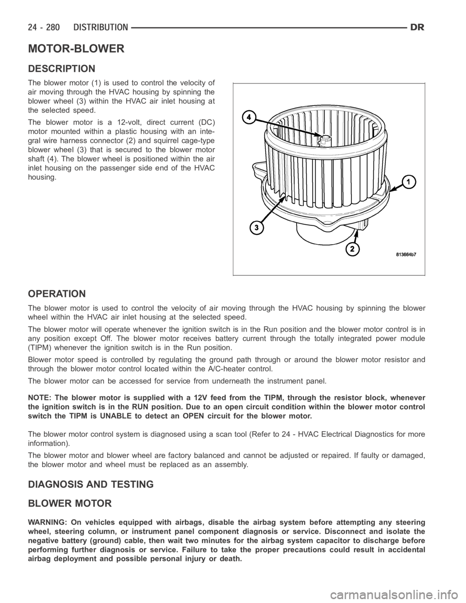
The blower motor (1) is used to control the velocity of
air moving through the HVAC housing by spinning the
blower wheel (3) within the HVAC air inlet housing at
the selected speed.
The blower motor is a 12-volt, direct current (DC)
motormountedwithinaplastichousingwithaninte-
gral wire harness connector (2) and squirrel cage-type
blower wheel (3) that is secured to the blower motor
shaft (4). The blower wheel is positioned within the air
inlet housing on the passenger side end of the HVAC
housing.
OPERATION
The blower motor is used to control the velocity of air moving through the HVAC housing by spinning the blower
wheel within the HVAC air inlet housing at the selected speed.
The blower motor will operate whenever the ignition switch is in the Run position and the blower motor control is in
any position except Off. The blower motor receives battery current through the totally integrated power module
(TIPM) whenever the ignition switch is in the Run position.
Blower motor speed is controlled by regulating the ground path through or around the blower motor resistor and
through the blower motor control located within the A/C-heater control.
The blower motor can be accessed for service from underneath the instrument panel.
NOTE: The blower motor is supplied with a 12V feed from the TIPM, through theresistor block, whenever
the ignition switch is in the RUN position. Due to an open circuit conditionwithin the blower motor control
switch the TIPM is UNABLE to detect an OPEN circuit for the blower motor.
The blower motor control system is diagnosed using a scan tool (Refer to 24 -HVAC Electrical Diagnostics for more
information).
The blower motor and blower wheel are factory balanced and cannot be adjusted or repaired. If faulty or damaged,
the blower motor and wheel must be replaced as an assembly.
DIAGNOSIS AND TESTING
BLOWER MOTOR
WARNING: On vehicles equipped with airbags, disable the airbag system before attempting any steering
wheel, steering column, or instrument panel component diagnosis or service. Disconnect and isolate the
negative battery (ground) cable, then wait two minutes for the airbag system capacitor to discharge before
performing further diagnosis or service. Failure to take the proper precautions could result in accidental
airbag deployment and possible personal injury or death.
Page 5123 of 5267
REMOVAL
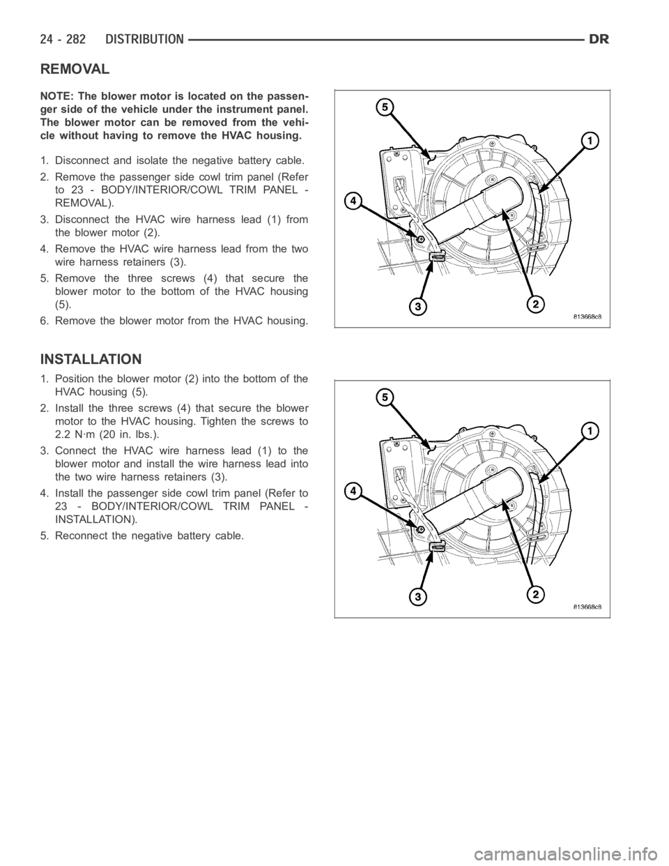
NOTE: The blower motor is located on the passen-
ger side of the vehicle under the instrument panel.
The blower motor can be removed from the vehi-
cle without having to remove the HVAC housing.
1. Disconnect and isolate the negative battery cable.
2. Remove the passenger side cowl trim panel (Refer
to 23 - BODY/INTERIOR/COWL TRIM PANEL -
REMOVAL).
3. Disconnect the HVAC wire harness lead (1) from
the blower motor (2).
4. Remove the HVAC wire harness lead from the two
wire harness retainers (3).
5. Remove the three screws (4) that secure the
blower motor to the bottom of the HVAC housing
(5).
6. Remove the blower motor from the HVAC housing.
INSTALLATION
1. Position the blower motor (2) into the bottom of the
HVAC housing (5).
2. Install the three screws (4) that secure the blower
motor to the HVAC housing. Tighten the screws to
2.2 Nꞏm (20 in. lbs.).
3. Connect the HVAC wire harness lead (1) to the
blower motor and install the wire harness lead into
the two wire harness retainers (3).
4. Install the passenger side cowl trim panel (Refer to
23 - BODY/INTERIOR/COWL TRIM PANEL -
INSTALLATION).
5. Reconnect the negative battery cable.
Page 5124 of 5267
OUTLETS-AIR
DESCRIPTION
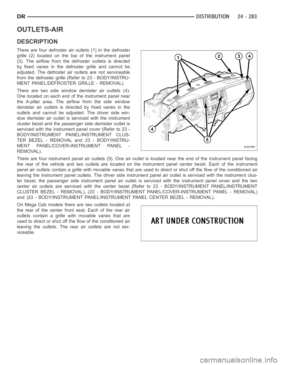
There are four defroster air outlets (1) in the defroster
grille (2) located on the top of the instrument panel
(3). The airflow from the defroster outlets is directed
by fixed vanes in the defroster grille and cannot be
adjusted. The defroster air outlets are not serviceable
from the defroster grille (Refer to 23 - BODY/INSTRU-
MENT PANEL/DEFROSTER GRILLE - REMOVAL).
There are two side window demister air outlets (4).
One located on each end of the instrument panel near
the A-pillar area. The airflow from the side window
demister air outlets is directed by fixed vanes in the
outlets and cannot be adjusted. The driver side win-
dow demister air outlet is serviced with the instrument
cluster bezel and the passenger side demister outlet is
serviced with the instrument panel cover (Refer to 23 -
BODY/INSTRUMENT PANEL/INSTRUMENT CLUS-
TER BEZEL - REMOVAL and 23 - BODY/INSTRU-
MENT PANEL/COVER-INSTRUMENT PANEL -
REMOVAL).
There are four instrument panel air outlets (5). One air outlet is located near the end of the instrument panel facing
the rear of the vehicle and two outlets are located on the instrument panel center bezel. Each of the instrument
panel air outlets contain a grille with movable vanes that are used to direct or shut off the flow of the conditioned air
leaving the instrument panel outlets. The driver side instrument panel air outlet is serviced with the instrument clus-
ter bezel, the passenger side instrument panel air outlet is serviced withthe instrument panel cover and the two
center air outlets are serviced with the center bezel (Refer to 23 - BODY/INSTRUMENT PANEL/INSTRUMENT
CLUSTER BEZEL - REMOVAL), (23 - BODY/INSTRUMENT PANEL/COVER-INSTRUMENTPA N E L - R E M O VA L )
and )23 - BODY/INSTRUMENT PANEL/INSTRUMENT PANEL CENTER BEZEL - REMOVAL).
On Mega Cab models there are two outlets located at
the rear of the center front seat. Each of the rear air
outlets contain a grille withmovable vanes that are
used to direct or shut off the flow of the conditioned air
leaving the outlets. The rear air outlets are not ser-
viceable.
Page 5151 of 5267
CORE-HEATER
DESCRIPTION
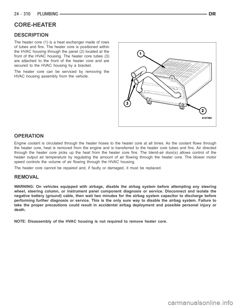
The heater core (1) is a heat exchanger made of rows
of tubes and fins. The heater core is positioned within
the HVAC housing through the panel (2) located at the
front of the HVAC housing. The heater core tubes (3)
are attached to the front of the heater core and are
secured to the HVAC housing by a bracket.
The heater core can be serviced by removing the
HVAC housing assembly from the vehicle.
OPERATION
Engine coolant is circulated through the heater hoses to the heater core atall times. As the coolant flows through
the heater core, heat is removed from the engine and is transferred to the heater core tubes and fins. Air directed
through the heater core picks up the heat from the heater core fins. The blend-air door(s) allows control of the
heater output air temperature by regulating the amount of air flowing through the heater core. The blower motor
speed controls the volume of air flowing through the HVAC housing.
The heater core cannot be repaired and, if faulty or damaged, it must be replaced.
REMOVAL
WARNING: On vehicles equipped with airbags, disable the airbag system before attempting any steering
wheel, steering column, or instrument panel component diagnosis or service. Disconnect and isolate the
negative battery (ground) cable, then wait two minutes for the airbag system capacitor to discharge before
performing further diagnosis or service. This is the only sure way to disable the airbag system. Failure to
take the proper precautions could result in accidental airbag deploymentand possible personal injury or
death.
NOTE: Disassembly of the HVAC housing is not required to remove heater core.
Page 5193 of 5267
EMISSIONS CONTROL
DESCRIPTION
STATE DISPLAY TEST MODE
The switch inputs to the Powertrain Control Module (PCM) have two recognized states; HIGH and LOW. For this
reason, the PCM cannot recognize the difference between a selected switchposition versus an open circuit, a short
circuit, or a defective switch. If the State Display screen shows the changefromHIGHtoLOWorLOWtoHIGH,
assume the entire switch circuit to the PCM functions properly. Connect the DRB scan tool to the data link con-
nector and access the state display screen. Then access either State Display Inputs and Outputs or State Display
Sensors.
CIRCUIT ACTUATION TEST MODE
The Circuit Actuation Test Mode checks for proper operation of output circuits or devices the Powertrain Control
Module (PCM) may not internally recognize. The PCM attempts to activate these outputs and allow an observer to
verify proper operation. Most of the tests provide an audible or visual indication of device operation (click of relay
contacts, fuel spray, etc.). Except for intermittent conditions, if a device functions properly during testing, assume the
device, its associated wiring, and driver circuit work correctly. Connect the DRB scan tool to the data link connector
and access the Actuators screen.
DIAGNOSTIC TROUBLE CODES
A Diagnostic Trouble Code (DTC) indicates the PCM has recognized an abnormal condition in the system.
Remember that DTC’s are the results of a system or circuit failure, but do not directly identify the failed
component or components.
BULB CHECK
Each time the ignition key is turned to the ON position, the malfunction indicator (check engine) lamp on the instru-
ment panel should illuminate for approximately 2 seconds then go out. Thisis done for a bulb check.
OBTAINING DTC’S USING DRB SCAN TOOL
1. Obtain the applicable Powertrain Diagnostic Manual.
2. Obtain the DRB Scan Tool.
3. Connect the DRB Scan Tool to the data link (diagnostic) connector. This connector is located in the passenger
compartment at the lower edge of instrument panel, and near the steering column.
4. Turn the ignition switch on and access the “Read Fault” screen.
5. Record all the DTC’s and “freeze frame” information shown on the DRB scantool.
6. To erase DTC’s, use the “Erase Trouble Code” data screen on the DRB scan tool.Do not erase any DTC’s
until problems have been investigated and repairs have been performed.
TA S K M A N A G E R
The PCM is responsible for efficiently coordinating the operation of all the emissions-related components. The PCM
is also responsible for determining if the diagnostic systems are operating properly. The software designed to carry
out these responsibilities is called the ’Task Manager’.
MONITORED SYSTEMS
There are new electronic circuit monitors that check fuel, emission, engine and ignition performance. These moni-
tors use information from various sensor circuits to indicate the overalloperation of the fuel, engine, ignition and
emission systems and thus the emissions performance of the vehicle.
The fuel, engine, ignition and emission systems monitors do not indicate aspecific component problem. They do
indicate that there is an implied problem within one of the systems and thata specific problem must be diagnosed.
If any of these monitors detect a problem affecting vehicle emissions, theMalfunction Indicator Lamp (MIL) will be
illuminated. These monitors generate Diagnostic Trouble Codes that can be displayed with the MIL or a scan tool.
Page 5197 of 5267
COMPONENT MONITORS
There are several components that will affect vehicle emissions if they malfunction. If one of these components
malfunctions the Malfunction Indicator Lamp (MIL) will illuminate.
Some of the component monitors are checking for proper operation of the part. Electrically operated components
now have input (rationality) and output (functionality) checks. Previously, a component like the Throttle Position sen-
sor (TPS) was checked by the PCM for an open or shorted circuit. If one of these conditions occurred, a DTC was
set. Now there is a check to ensure that the component is working. This is donebywatchingforaTPSindication
of a greater or lesser throttle opening than MAP and engine rpm indicate. Inthe case of the TPS, if engine vacuum
is high and engine rpm is 1600 or greater, and the TPS indicates a large throttle opening, a DTC will be set. The
same applies to low vacuum if the TPS indicates a small throttle opening.
All open/short circuit checks, or any component that has an associated limp-in, will set a fault after 1 trip with the
malfunction present. Components without an associated limp-in will taketwo trips to illuminate the MIL.
OPERATION
OPERATION
The Powertrain Control Module (PCM) monitors many
different circuits in the fuel injection, ignition, emission
and engine systems. If the PCM senses a problem
withamonitoredcircuitoftenenoughtoindicatean
actual problem, it stores a Diagnostic Trouble Code
(DTC) in the PCM’s memory. If the problem is repaired
or ceases to exist, the PCM cancels the code after 40
warm-up cycles. Diagnostic trouble codes that affect
vehicle emissions illuminatethe Malfunction Indicator
Lamp (MIL). The MIL is displayed as an engine icon
(graphic) on the instrument panel. Refer to Malfunction
Indicator Lamp in this section.
Certain criteria must be met before the PCM stores a
DTC in memory. The criteria may be a specific range
of engine RPM, engine temperature, and/or input volt-
age to the PCM.
The PCM might not store a DTC for a monitored cir-
cuit even though a malfunction has occurred. This
may happen because one of the DTC criteria for the
circuit has not been met.For example,assume the diagnostic trouble code criteria requires the PCM to monitor the
circuit only when the engine operates between 750 and 2000 RPM. Suppose thesensor’s output circuit shorts to
ground when engine operates above 2400 RPM (resulting in 0 volt input to thePCM). Because the condition hap-
pens at an engine speed above the maximum threshold (2000 rpm), the PCM willnot store a DTC.
There are several operating conditions for which the PCM monitors and setsDTC’s. Refer to Monitored Systems,
Components, and Non-Monitored Circuits in this section.
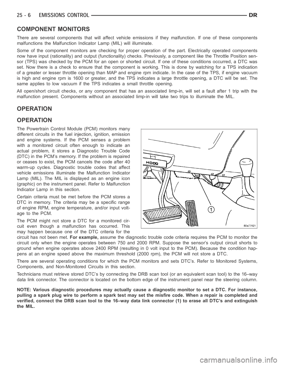
Technicians must retrieve stored DTC’s by connecting the DRB scan tool (oran equivalent scan tool) to the 16–way
data link connector. The connector is located on the bottom edge of the instrument panel near the steering column.
NOTE: Various diagnostic procedures may actually cause a diagnostic monitor to set a DTC. For instance,
pulling a spark plug wire to perform a spark test may set the misfire code. When a repair is completed and
verified, connect the DRB scan tool to the 16–way data link connector (1) toerase all DTC’s and extinguish
the MIL.