2006 DODGE RAM SRT-10 flat tire
[x] Cancel search: flat tirePage 4323 of 5267
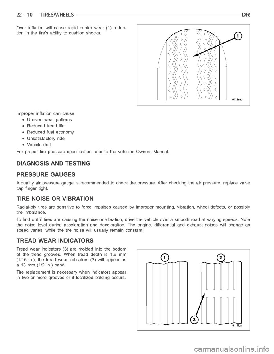
Over inflation will cause rapid center wear (1) reduc-
tion in the tire’s ability to cushion shocks.
Improper inflation can cause:
Uneven wear patterns
Reduced tread life
Reduced fuel economy
Unsatisfactory ride
Vehicle drift
For proper tire pressure specification refer to the vehicles Owners Manual.
DIAGNOSIS AND TESTING
PRESSURE GAUGES
A quality air pressure gauge is recommended to check tire pressure. After checking the air pressure, replace valve
cap finger tight.
TIRE NOISE OR VIBRATION
Radial-ply tires are sensitive to force impulses caused by improper mounting, vibration, wheel defects, or possibly
tire imbalance.
To find out if tires are causing the noise or vibration, drive the vehicle over a smooth road at varying speeds. Note
the noise level during acceleration and deceleration. The engine, differential and exhaust noises will change as
speed varies, while the tire noise will usually remain constant.
TREAD WEAR INDICATORS
Tread wear indicators (3) are molded into the bottom
of the tread grooves. When tread depth is 1.6 mm
(1/16 in.), the tread wear indicators (3) will appear as
a 13 mm (1/2 in.) band.
Tire replacement is necessary when indicators appear
in two or more grooves or if localized balding occurs.
Page 4324 of 5267
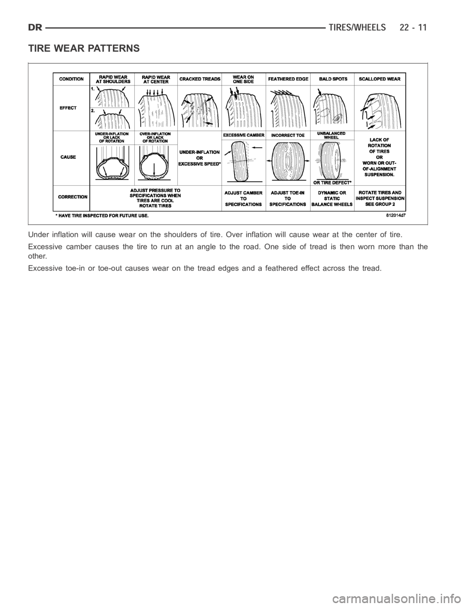
TIRE WEAR PATTERNS
Under inflation will cause wear on the shoulders of tire. Over inflation will cause wear at the center of tire.
Excessive camber causes the tire to run at an angle to the road. One side of tread is then worn more than the
other.
Excessive toe-in or toe-out causes wear on the tread edges and a feathered effect across the tread.
Page 4326 of 5267
STANDARD PROCEDURE
TIRE REPAIR AREA
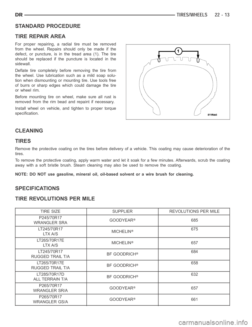
For proper repairing, a radial tire must be removed
from the wheel. Repairs should only be made if the
defect, or puncture, is in the tread area (1). The tire
should be replaced if the puncture is located in the
sidewall.
Deflate tire completely before removing the tire from
the wheel. Use lubrication such as a mild soap solu-
tion when dismounting or mounting tire. Use tools free
of burrs or sharp edges which could damage the tire
or wheel rim.
Before mounting tire on wheel, make sure all rust is
removed from the rim bead and repaint if necessary.
Install wheel on vehicle, and tighten to proper torque
specification.
CLEANING
TIRES
Remove the protective coating on the tires before delivery of a vehicle. This coating may cause deterioration of the
tires.
To remove the protective coating, apply warm water and let it soak for a few minutes. Afterwards, scrub the coating
away with a soft bristle brush. Steam cleaning may also be used to remove thecoating.
NOTE: DO NOT use gasoline, mineral oil, oil-based solvent or a wire brush for cleaning.
SPECIFICATIONS
TIRE REVOLUTIONS PER MILE
TIRE SIZE SUPPLIER REVOLUTIONS PER MILE
P245/70R17
WRANGLER SRAGOODYEAR
685
LT245/70R17
LT X A / SMICHELIN
675
LT265/70R17E
LT X A / SMICHELIN
657
LT245/70R17
RUGGED TRAIL T/ABF GOODRICH
684
LT265/70R17E
RUGGED TRAIL T/ABF GOODRICH
658
LT285/70R17D
ALL TERRAIN T/ABF GOODRICH
632
P265/70R17
WRANGLER SR/AGOODYEAR
657
P265/70R17
WRANGLER GS/AGOODYEAR
661
Page 4329 of 5267
WHEEL DESIGN
The rim size is on the vehicle safety certification label
located on the drivers door shut face. The size of the
rim is determined by the drivetrain package. Original
equipment wheels/rims are designed for operation up
to the specified maximum vehicle capacity.
All models use stamped steel, cast aluminum or
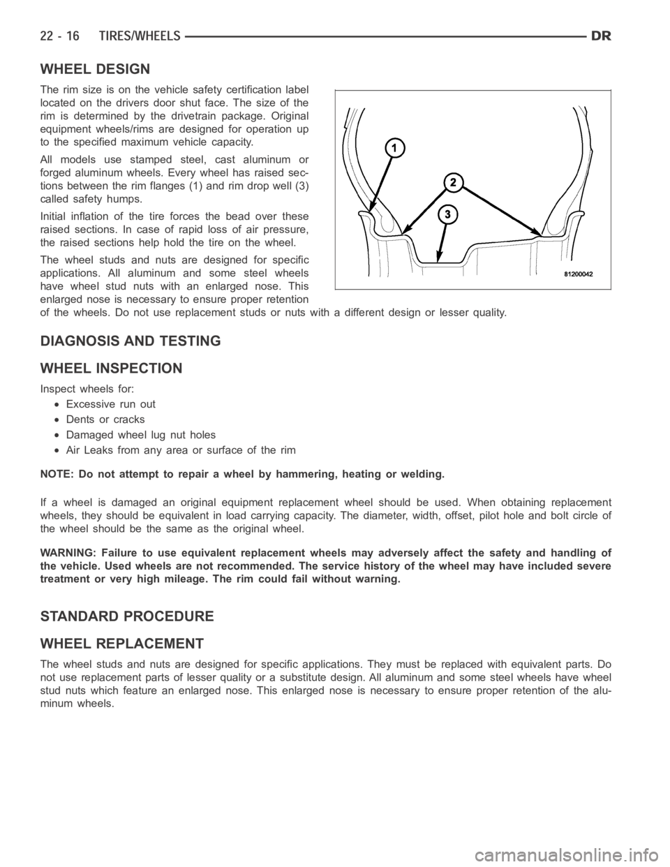
forged aluminum wheels. Every wheel has raised sec-
tions between the rim flanges (1) and rim drop well (3)
called safety humps.
Initial inflation of the tire forces the bead over these
raised sections. In case of rapid loss of air pressure,
the raised sections help hold the tire on the wheel.
The wheel studs and nuts are designed for specific
applications. All aluminum and some steel wheels
have wheel stud nuts with an enlarged nose. This
enlarged nose is necessary to ensure proper retention
of the wheels. Do not use replacement studs or nuts with a different design orlesserquality.
DIAGNOSIS AND TESTING
WHEEL INSPECTION
Inspect wheels for:
Excessive run out
Dents or cracks
Damaged wheel lug nut holes
Air Leaks from any area or surface of the rim
NOTE: Do not attempt to repair a wheel by hammering, heating or welding.
If a wheel is damaged an original equipment replacement wheel should be used. When obtaining replacement
wheels, they should be equivalent in load carrying capacity. The diameter, width, offset, pilot hole and bolt circle of
the wheel should be the same as the original wheel.
WARNING: Failure to use equivalent replacement wheels may adversely affect the safety and handling of
the vehicle. Used wheels are not recommended. The service history of the wheel may have included severe
treatment or very high mileage. The rim could fail without warning.
STANDARD PROCEDURE
WHEEL REPLACEMENT
The wheel studs and nuts are designed for specific applications. They mustbe replaced with equivalent parts. Do
not use replacement parts of lesser quality or a substitute design. All aluminum and some steel wheels have wheel
stud nuts which feature an enlarged nose. This enlarged nose is necessary to ensure proper retention of the alu-
minum wheels.
Page 4331 of 5267
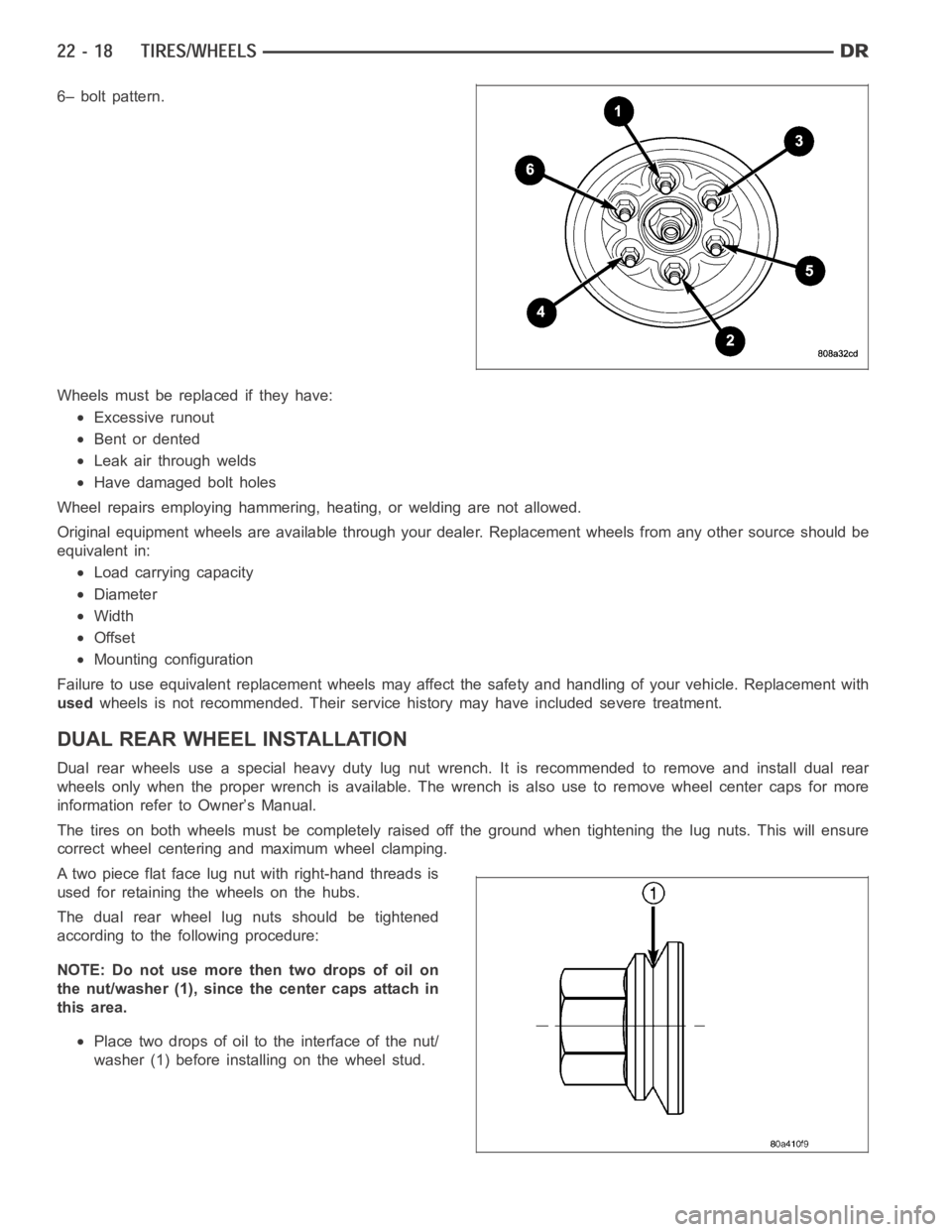
6– bolt pattern.
Wheels must be replaced if they have:
Excessive runout
Bent or dented
Leak air through welds
Have damaged bolt holes
Wheel repairs employing hammering, heating, or welding are not allowed.
Original equipment wheels are available through your dealer. Replacement wheels from any other source should be
equivalent in:
Load carrying capacity
Diameter
Width
Offset
Mounting configuration
Failure to use equivalent replacement wheels may affect the safety and handling of your vehicle. Replacement with
usedwheels is not recommended. Their service history may have included severetreatment.
DUAL REAR WHEELINSTALLATION
Dual rear wheels use a special heavy duty lug nut wrench. It is recommended to remove and install dual rear
wheels only when the proper wrench is available. The wrench is also use to remove wheel center caps for more
information refer to Owner’s Manual.
The tires on both wheels must be completely raised off the ground when tightening the lug nuts. This will ensure
correct wheel centering and maximum wheel clamping.
A two piece flat face lug nut with right-hand threads is
used for retaining the wheels on the hubs.
The dual rear wheel lug nuts should be tightened
according to the following procedure:
NOTE: Do not use more then two drops of oil on
the nut/washer (1), since the center caps attach in
this area.
Place two drops of oil to the interface of the nut/
washer (1) before installing on the wheel stud.
Page 4333 of 5267

STUDS
REMOVAL
1. Raise and support the vehicle.
2. Remove the wheel and tire assembly.
3. Remove the brake caliper, caliper adapter and
rotor, (Refer to 5 - BRAKES/HYDRAULIC/ME-
CHANICAL/ROTORS - REMOVAL).
4. Remove the wheel speed sensor from the hub.
5. Press the stud from the hub using remover
C-4150A (1).
6. Remove the stud (2) from the hub (1) through the
backing plate access hole (3).
INSTALLATION
1. Install the new stud (2) into the hub flange (1).
2. Install three proper sized washers onto the stud,
then install lug nut with the flat side of the nut
against the washers.
3. Tighten the lug nut until the stud is pulled into the
hub flange. Verify that the stud is properly seated
into the flange.
4. Remove the lug nut and washers.
5. Install the brake rotor, caliper adapter, and caliper,
(Refer to 5 - BRAKES/HYDRAULIC/MECHANICAL/
ROTORS - INSTALLATION).
6. Install the wheel speed sensor.
7. Install the wheel and tire assembly, use new lug nut on the stud or studs that were replaced.
Page 4335 of 5267
WHEEL COVER
REMOVAL
NOTE: The hub caps must be removed before raising the vehicle off the ground.
NOTE: You must use the flat end of the hub/cap remover/installer combination tool to pry off the wheel
skins. Insert the flat tip completely and using a back and forth motion, loosen the wheel skin. repeat this
procedure around the tire until the wheel skin pops off.
1. On 2500/3500 single rear wheel (SRW) models, insert a hub/cap remover/installer combination tool using the
blade on the end of the tool to pry the cap off in a back and forth motion.
2. On 3500 models with dual rear wheels (DRW), you must first remove the hub caps. The hub/cap remover/in-
staller combination tool must be inserted in the pry off notch of the rear hubcaps.
3. Position the hub/cap remover/installer combination tool and pull out on the tool firmly. The cap should come off.
NOTE: Failure to use a back and forth motion could damage the wheel skin chrome finish.
4. The wheel skins can now be removed from the wheel. Use the flat end of the lug nut wrench to pry off the wheel
skins. Make sure that the flat end is inserted and use a back and forth motionto remove the wheel skin.
5. On 3500 models front hub caps use the hub/cap remover/installer combination tool to pry off the cap in a back
and forth motion. The wheel skins can now be removed.
INSTALLATION
REAR
1. Install one 1 1/2 in. valve stem extension on each rear inner wheel.
NOTE: A 3/8 in. drive 10mm deep wheel socket with a 10 in. or greater extension can be used to remove the
existing valve stem cap and install the extension.
2. Install one 1 in. valve stem extension on each outer wheel.
3. Align the cooling windows of the wheel skin with the cooling windows of the wheel. Seat one side of the wheel
skin’s retainer onto the wheel. Using a rubber mallet, strike thew wheel skin on the outer circumference. Strike at
several locations around the circumference until the skin is fully seated.
NOTE: The wheel skin and the hub cap are fully seated when there is a consistent gap between the skin/cap
and the wheel.
4. Tug on the hub/cap wheel skin to ensure that they are properly installed.
FRONT
1. Alignthevalvestemwiththenotchinthewheelskin.
2. Seat on side of the wheel skin’s wire retainer on to the wheel.
3. Using a rubber mallet, strike the opposite side of the wheel skin until the skin is properly seated.
NOTE: The wheel skin and the hub cap are fully seated when there is a consistant gap between the skin/
cap and the wheel.
4. Tug on the hub cap/wheel skin to ensure that they are properly installed.
Page 5127 of 5267
PLUMBING
DESCRIPTION
The A/C refrigerant lines and hoses are used to carry the refrigerant between the various A/C system components.
The refrigerant lines and hoses for the R-134a system on this vehicle consist of a barrier-hose design with a nylon
tube sandwiched between rubber layers. The nylon tube helps to contain theR-134a refrigerant, which has a
smaller molecular structure than R-12 refrigerant. The ends of the refrigerant lines are made from lightweight alu-
minum or steel, and commonly use braze-less fittings.
Any kinks or sharp bends in the refrigerant lines and hoses will reduce the capacity of the entire A/C system and
can reduce the flow of refrigerant in the system. The radius of all bends in the flexible hose refrigerant lines should
be at least ten times the diameter of the hose and the refrigerant lines should be routed so they are at least 80
millimeters (3 inches) away from the exhaust manifold(s) and exhaust pipe(s).
OPERATION
High pressures are produced in the refrigerant system when the A/C compressor is operating. Extreme care must
be exercised to make sure that each of the refrigerant system connections is pressure-tight and leak free. It is a
good practice to inspect all flexible hose refrigerant lines at least oncea year to make sure they are in good con-
dition and properly routed.
The refrigerant lines and hoses are coupled to other A/C system componentswith block-type fittings. An O-ring seal,
or a flat steel gasket with an integral O-ring (dual plane seal), is used to mate the refrigerant line fittings with A/C
system components to ensure the integrity of the refrigerant system.
The refrigerant lines and hoses cannot be repaired and, if faulty or damaged, they must be replaced.
WARNING
WARNING: The A/C system contains refrigerant under high pressure. Repairs should only be performed by
qualified service personnel. Severe personal injury or death may result from improper service procedures.
WARNING: Avoid breathing the refrigerant and refrigerant oil vapor or mist. Exposure may irritate the eyes,
nose, and/or throat. Wear eye protection when servicing the A/C refrigerant system. Serious eye injury can
result from direct contact with the refrigerant. If eye contact occurs, seek medical attention immediately.
WARNING: Do not expose the refrigerant to open flame. Poisonous gas is createdwhenrefrigerantis
burned. An electronic leak detector is recommended. Severe personal injury or death may result from
improper service procedures.
WARNING: If accidental system discharge occurs, ventilate the work area before resuming service. Large
amounts of refrigerant released in a closed work area will displace the oxygen and cause suffocation and
death.
WARNING: The evaporation rate of R-134a refrigerant at average temperature and altitude is extremely high.
As a result, anything that comes in contact with the refrigerant will freeze. Always protect the skin or del-
icate objects from direct contact with the refrigerant.
WARNING: The R-134a service equipment or the vehicle refrigerant system should not be pressure tested or
leak tested with compressed air. Some mixtures of air and R-134a have been shown to be combustible at
elevated pressures. These mixtures are potentially dangerous, and may result in fire or explosion causing
property damage, personal injury or death.