2006 DODGE RAM SRT-10 check oil
[x] Cancel search: check oilPage 5144 of 5267
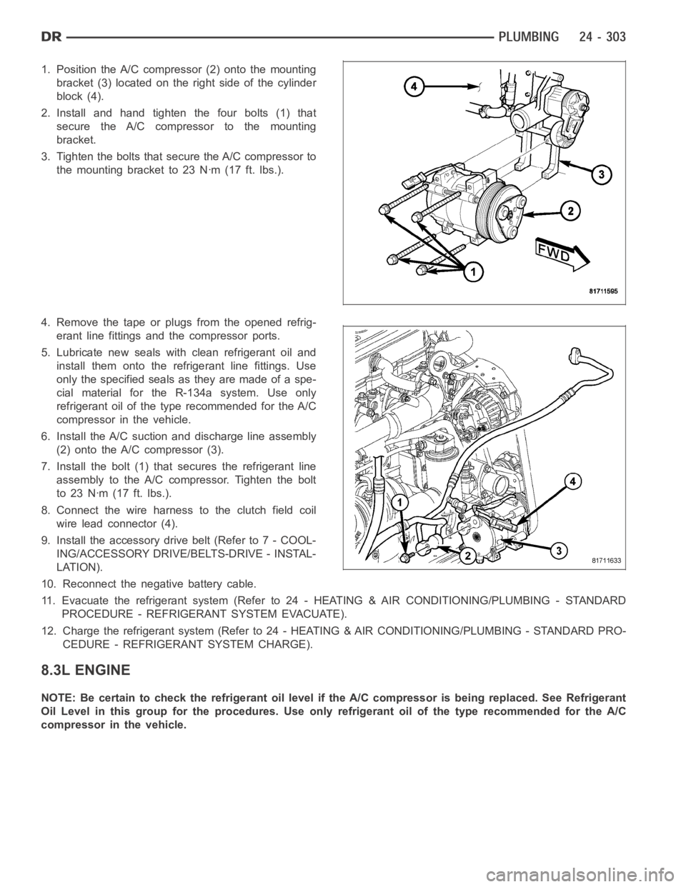
1. Position the A/C compressor (2) onto the mounting
bracket (3) located on the right side of the cylinder
block (4).
2. Install and hand tighten the four bolts (1) that
secure the A/C compressor to the mounting
bracket.
3. Tighten the bolts that secure the A/C compressor to
themountingbracketto23Nꞏm(17ft.lbs.).
4. Remove the tape or plugs from the opened refrig-
erant line fittings and the compressor ports.
5. Lubricate new seals with clean refrigerant oil and
install them onto the refrigerant line fittings. Use
only the specified seals as they are made of a spe-
cial material for the R-134a system. Use only
refrigerant oil of the type recommended for the A/C
compressor in the vehicle.
6. Install the A/C suction and discharge line assembly
(2) onto the A/C compressor (3).
7. Install the bolt (1) that secures the refrigerant line
assembly to the A/C compressor. Tighten the bolt
to 23 Nꞏm (17 ft. lbs.).
8. Connect the wire harness to the clutch field coil
wire lead connector (4).
9. Install the accessory drive belt (Refer to 7 - COOL-
ING/ACCESSORY DRIVE/BELTS-DRIVE - INSTAL-
LATION).
10. Reconnect the negative battery cable.
11. Evacuate the refrigerant system (Refer to 24 - HEATING & AIR CONDITIONING/PLUMBING - STANDARD
PROCEDURE - REFRIGERANT SYSTEM EVACUATE).
12. Charge the refrigerant system (Refer to 24 - HEATING & AIR CONDITIONING/PLUMBING - STANDARD PRO-
CEDURE - REFRIGERANT SYSTEM CHARGE).
8.3L ENGINE
NOTE: Be certain to check the refrigerant oil level if the A/C compressor isbeing replaced. See Refrigerant
Oil Level in this group for the procedures. Use only refrigerant oil of the type recommended for the A/C
compressor in the vehicle.
Page 5156 of 5267
1. Recover the refrigerant from the refrigerant system
(Refer to 24 - HEATING & AIR CONDITIONING/
PLUMBING - STANDARD PROCEDURE -
REFRIGERANT SYSTEM RECOVERY).
2. Remove the secondary retaining clip from the
spring-lock type refrigerant line coupler.
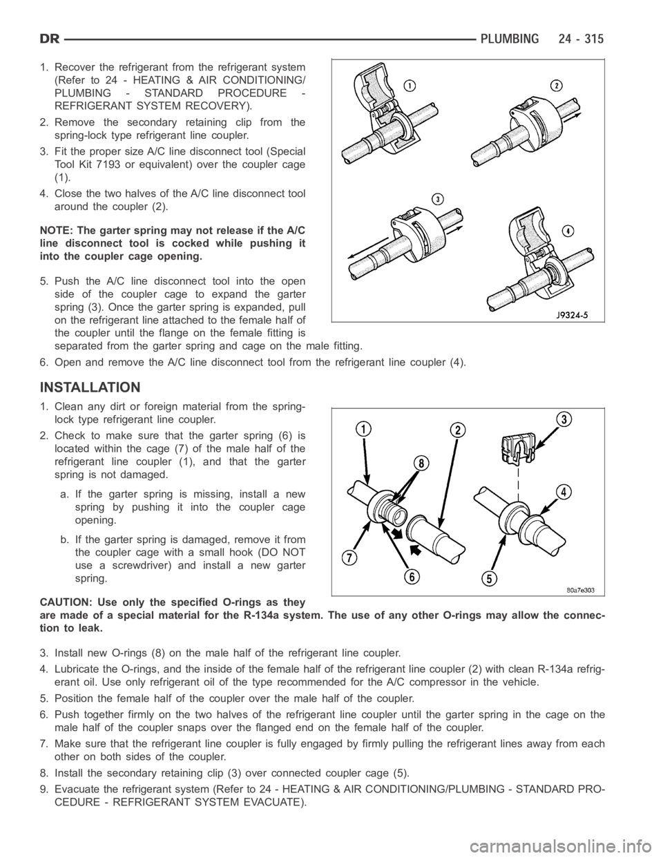
3. Fit the proper size A/C line disconnect tool (Special
Tool Kit 7193 or equivalent) over the coupler cage
(1).
4. Close the two halves of the A/C line disconnect tool
around the coupler (2).
NOTE: The garter spring may not release if the A/C
line disconnect tool is cocked while pushing it
into the coupler cage opening.
5. Push the A/C line disconnect tool into the open
side of the coupler cage to expand the garter
spring (3). Once the garter spring is expanded, pull
on the refrigerant line attached to the female half of
the coupler until the flange on the female fitting is
separated from the garter spring and cage on the male fitting.
6. Open and remove the A/C line disconnect tool from the refrigerant line coupler (4).
INSTALLATION
1. Clean any dirt or foreign material from the spring-
lock type refrigerant line coupler.
2. Check to make sure that the garter spring (6) is
located within the cage (7) of the male half of the
refrigerant line coupler (1), and that the garter
spring is not damaged.
a. If the garter spring is missing, install a new
spring by pushing it into the coupler cage
opening.
b. If the garter spring is damaged, remove it from
the coupler cage with a small hook (DO NOT
use a screwdriver) and install a new garter
spring.
CAUTION: Use only the specified O-rings as they
are made of a special material for the R-134a system. The use of any other O-rings may allow the connec-
tion to leak.
3. Install new O-rings (8) on the male half of the refrigerant line coupler.
4. Lubricate the O-rings, and the inside of the female half of the refrigerant line coupler (2) with clean R-134a refrig-
erant oil. Use only refrigerant oil of the type recommended for the A/C compressor in the vehicle.
5. Position the female half of the coupler over the male half of the coupler.
6. Push together firmly on the two halves of the refrigerant line coupler until the garter spring in the cage on the
male half of the coupler snaps over the flanged end on the female half of the coupler.
7. Make sure that the refrigerant line coupler is fully engaged by firmly pulling the refrigerant lines away from each
other on both sides of the coupler.
8. Install the secondary retaining clip (3) over connected coupler cage (5).
9. Evacuate the refrigerant system (Refer to 24 - HEATING & AIR CONDITIONING/PLUMBING - STANDARD PRO-
CEDURE - REFRIGERANT SYSTEM EVACUATE).
Page 5188 of 5267
OIL-A/C REFRIGERANT
DESCRIPTION
The refrigerant oil used in R-134a refrigerant systems is a synthetic-based, polyalkylene glycol (PAG), wax-free
lubricant. Mineral-based R-12 refrigerant oils are not compatible with PAG oils, and should never be introduced to
an R-134a refrigerant system.
There are different PAG oils available, and each contains a different additive package. Useonlyrefrigerant oil of the
same type as recommended to service the refrigerant system (always refer to the specification tagincluded with
the replacement A/C compressor or the A/C Underhood Specification Label located in the engine compartment).
The Denso 10S17 A/C compressor used in this vehicle when equipped with the 3.7L, 4.7L, 5.7L or 8.3L engine is
designed to use ND-8 PAG refrigerant oil. Use only this type of refrigerantoil when servicing the A/C compressor for
these engines.
The Visteon HS-18 A/C compressor used in this vehicle when equipped with 5.9L diesel engine is designed to use
VC-46 PAG refrigerant oil. Use only this type of refrigerant oil when servicing this A/C compressor.
OPERATION
After performing any refrigerant recovery or recycling operation, always replenish the refrigerant system with the
same amount of the recommended refrigerant oil as was removed. Too little refrigerant oil can cause A/C compres-
sor damage, and too much can reduce A/C system performance.
PAG refrigerant oil is more hygroscopic than mineral oil, and will absorb any moisture it comes into contact with,
even moisture in the air. The PAG oil container should always be kept tightly capped until it is ready to be used.
After use, recap the oil container immediately to prevent moisture contamination.
STANDARD PROCEDURE
REFRIGERANT OIL LEVEL
When an A/C system is assembled at the factory, all components except the A/C compressor are refrigerant oil free.
After the refrigerant system has been charged and operated, the refrigerant oil in the A/C compressor is dispersed
throughout the refrigerant system. The accumulator, A/C evaporator, A/Ccondenser and the A/C compressor will
each retain a significant amount of the needed refrigerant oil.
It is important to have the correct amount of refrigerant oil in the A/C system. This ensures proper lubrication of the
A/C compressor. Too little oil will result in damage to the A/C compressor,while too much oil will reduce the cooling
capacity of the A/C system and consequently result in higher discharge airtemperatures.
CAUTION: The refrigerant oil in the R-134a A/C system is unique depending on the A/C compressor used.
Use only PAG oils that are designed to work with R-134a refrigerant and the A/C compressor in the vehicle.
Always refer to the A/C Underhood Specification Label for the correct oil designation. The oil container
should be kept tightly capped until it is ready for use and then tightly capped after use to prevent contam-
ination from dirt and moisture. Refrigerant oil will quickly absorb any moisture it comes in contact with,
therefore, special effort must be used to keep all R-134a system components moisture-free. Moisture in the
refrigerant oil is very difficult toremove and will cause a reliability problem with the A/C compressor.
NOTE: Most reclaim/recycling equipment will measure the lubricant beingremoved during recovery. This
amount of lubricant should be added back into the system. Refer to the reclaim/recycling equipment man-
ufacturers instructions.
It will not be necessary to check the oil level in the A/C compressor or to addoil, unless there has been an oil loss.
An oil loss may occur due to a rupture or leak from a refrigerant line, a connector fitting, a component, or a com-
ponent seal. If a leak occurs, add 30 milliliters (1 fluid ounce) of refrigerant oil to the refrigerant system after the
repair has been made. Refrigerant oil loss will be evident at the leak pointby the presence of a wet, shiny surface
around the leak.
Refrigerant oil must be added when an accumulator, A/C evaporator or A/C condenser is replaced. See the Refrig-
erant Oil Capacities chart. When an A/C compressor is replaced, the refrigerant oil must be drained from the old
Page 5224 of 5267
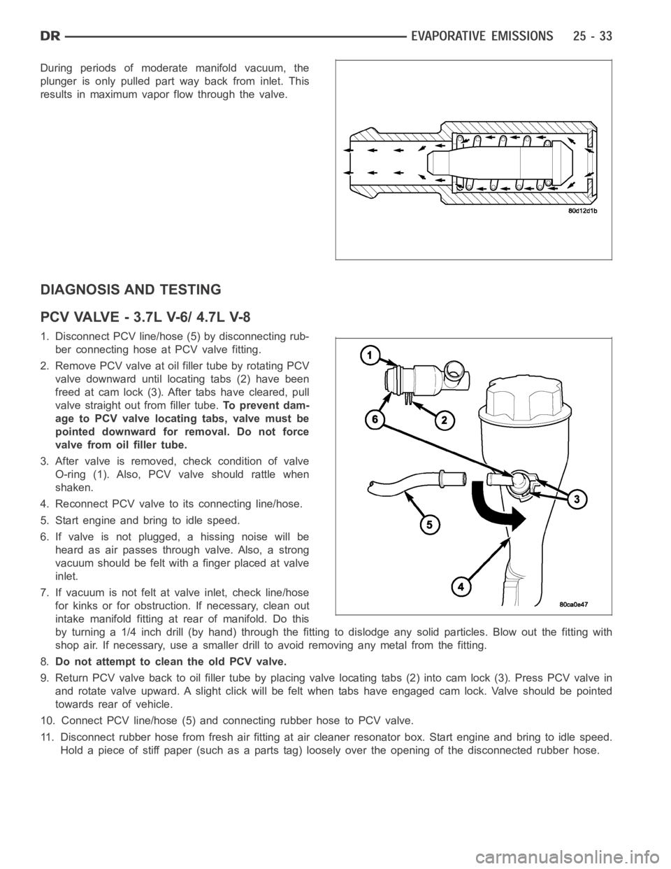
During periods of moderate manifold vacuum, the
plunger is only pulled part way back from inlet. This
results in maximum vapor flow through the valve.
DIAGNOSIS AND TESTING
PCVVALVE-3.7LV-6/4.7LV-8
1. Disconnect PCV line/hose (5) by disconnecting rub-
ber connecting hose at PCV valve fitting.
2. Remove PCV valve at oil filler tube by rotating PCV
valve downward until locating tabs (2) have been
freed at cam lock (3). After tabs have cleared, pull
valve straight out from filler tube.To prevent dam-
age to PCV valve locating tabs, valve must be
pointed downward for removal. Do not force
valve from oil filler tube.
3. After valve is removed, check condition of valve
O-ring (1). Also, PCV valve should rattle when
shaken.
4. Reconnect PCV valve to its connecting line/hose.
5. Start engine and bring to idle speed.
6. If valve is not plugged, a hissing noise will be
heard as air passes through valve. Also, a strong
vacuum should be felt with a finger placed at valve
inlet.
7. If vacuum is not felt at valve inlet, check line/hose
for kinks or for obstruction. If necessary, clean out
intake manifold fitting at rear of manifold. Do this
byturninga1/4inchdrill(byhand)throughthefittingtodislodgeanysolid particles. Blow out the fitting with
shop air. If necessary, use a smaller drill to avoid removing any metal fromthe fitting.
8.Do not attempt to clean the old PCV valve.
9. Return PCV valve back to oil filler tube by placing valve locating tabs (2) into cam lock (3). Press PCV valve in
and rotate valve upward. A slight click will be felt when tabs have engaged cam lock. Valve should be pointed
towards rear of vehicle.
10. Connect PCV line/hose (5) and connecting rubber hose to PCV valve.
11. Disconnect rubber hose from fresh air fitting at air cleaner resonatorbox. Start engine and bring to idle speed.
Hold a piece of stiff paper (such as a parts tag) loosely over the opening of the disconnected rubber hose.
Page 5226 of 5267
REMOVAL
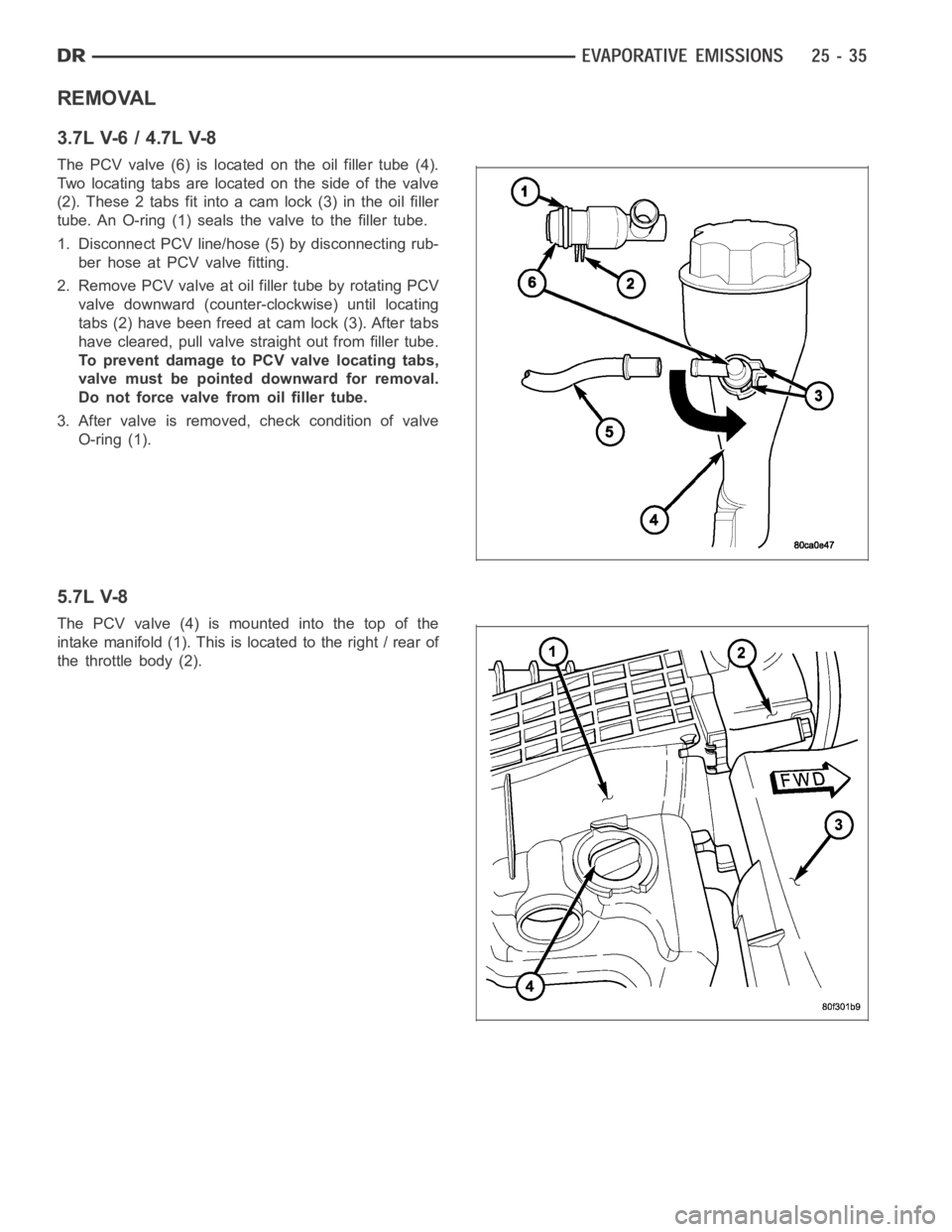
3.7L V-6 / 4.7L V-8
The PCV valve (6) is located on the oil filler tube (4).
Two locating tabs are located on the side of the valve
(2). These 2 tabs fit into a cam lock (3) in the oil filler
tube. An O-ring (1) seals the valve to the filler tube.
1. Disconnect PCV line/hose (5) by disconnecting rub-
ber hose at PCV valve fitting.
2. Remove PCV valve at oil filler tube by rotating PCV
valve downward (counter-clockwise) until locating
tabs (2) have been freed at cam lock (3). After tabs
have cleared, pull valve straight out from filler tube.
To prevent damage to PCV valve locating tabs,
valve must be pointed downward for removal.
Do not force valve from oil filler tube.
3. After valve is removed, check condition of valve
O-ring (1).
5.7L V-8
The PCV valve (4) is mounted into the top of the
intake manifold (1). This is located to the right / rear of
the throttle body (2).
Page 5227 of 5267
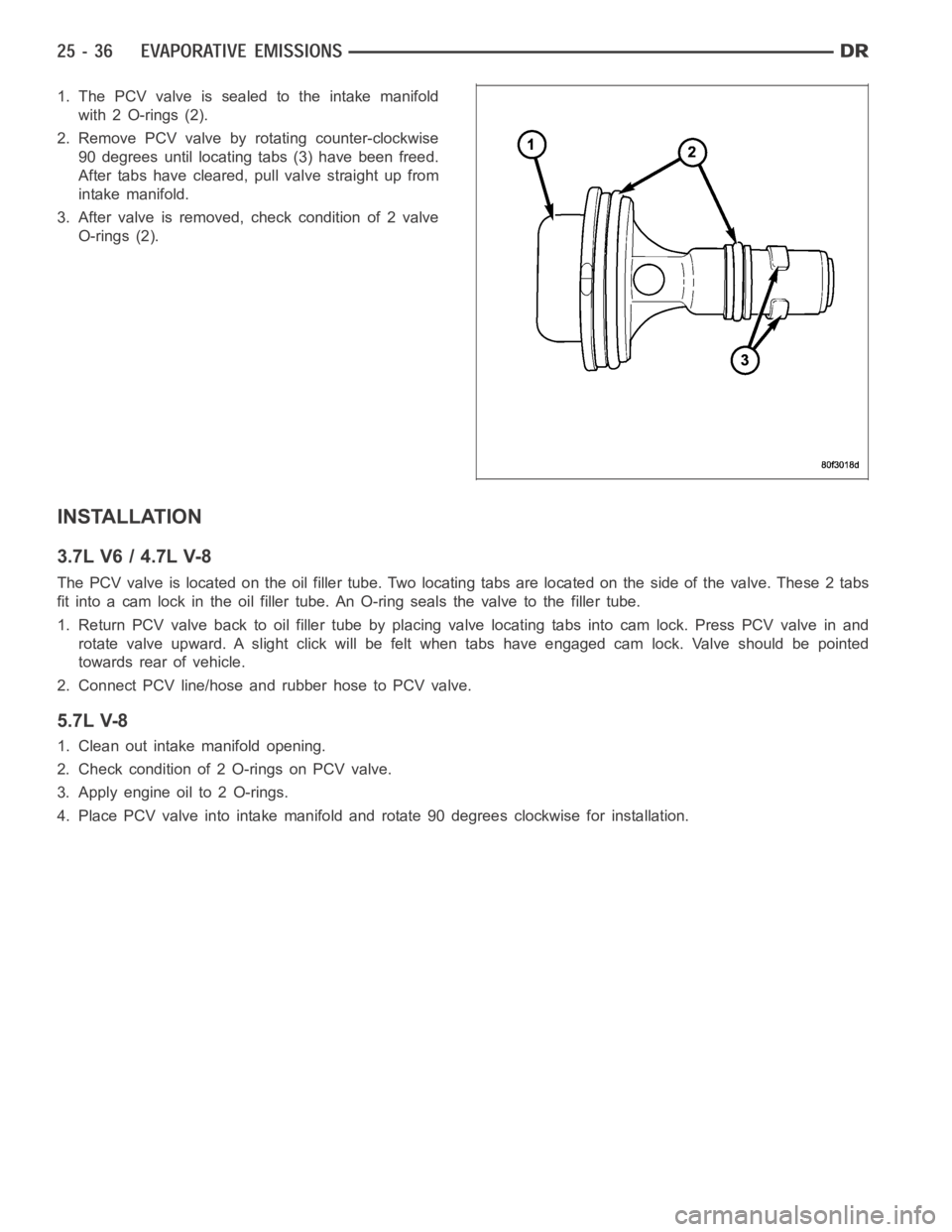
1. The PCV valve is sealed to the intake manifold
with 2 O-rings (2).
2. Remove PCV valve by rotating counter-clockwise
90 degrees until locating tabs (3) have been freed.
After tabs have cleared, pull valve straight up from
intake manifold.
3. After valve is removed, check condition of 2 valve
O-rings (2).
INSTALLATION
3.7L V6 / 4.7L V-8
The PCV valve is located on the oil filler tube. Two locating tabs are locatedonthesideofthevalve.These2tabs
fit into a cam lock in the oil filler tube.An O-ring seals the valve to the filler tube.
1. Return PCV valve back to oil filler tube by placing valve locating tabs into cam lock. Press PCV valve in and
rotate valve upward. A slight click will be felt when tabs have engaged cam lock. Valve should be pointed
towards rear of vehicle.
2. Connect PCV line/hose and rubber hose to PCV valve.
5.7L V-8
1. Clean out intake manifold opening.
2. Check condition of 2 O-rings on PCV valve.
3. Apply engine oil to 2 O-rings.
4. Place PCV valve into intake manifold and rotate 90 degrees clockwise forinstallation.