2006 DODGE RAM SRT-10 check oil
[x] Cancel search: check oilPage 3937 of 5267
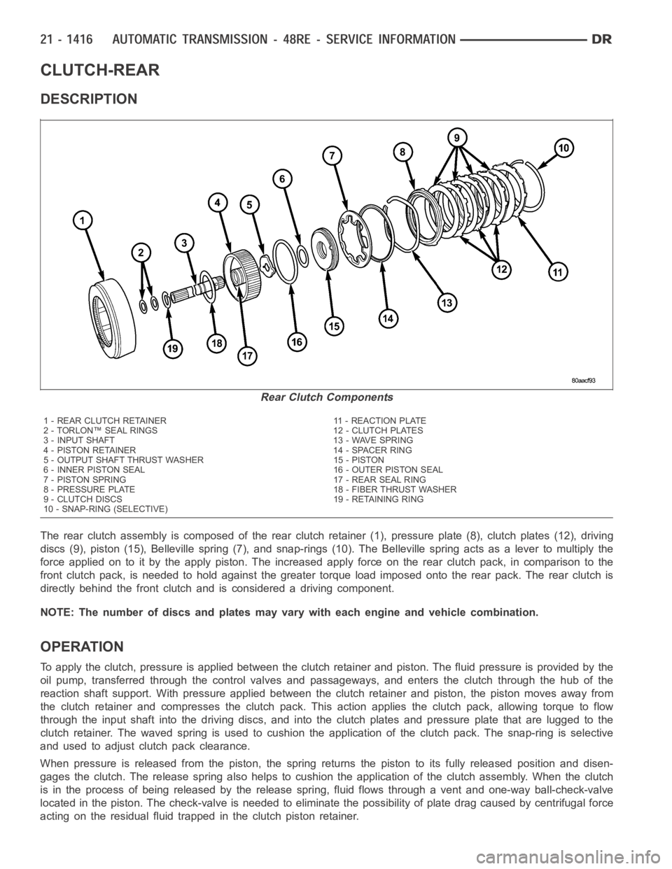
CLUTCH-REAR
DESCRIPTION
The rear clutch assembly is composed of the rear clutch retainer (1), pressure plate (8), clutch plates (12), driving
discs (9), piston (15), Belleville spring (7), and snap-rings (10). The Belleville spring acts as a lever to multiply the
force applied on to it by the apply piston. The increased apply force on the rear clutch pack, in comparison to the
front clutch pack, is needed to hold against the greater torque load imposed onto the rear pack. The rear clutch is
directly behind the front clutch and is considered a driving component.
NOTE: The number of discs and plates may vary with each engine and vehicle combination.
OPERATION
To apply the clutch, pressure is applied between the clutch retainer and piston. The fluid pressure is provided by the
oil pump, transferred through the control valves and passageways, and enters the clutch through the hub of the
reaction shaft support. With pressure applied between the clutch retainer and piston, the piston moves away from
the clutch retainer and compresses the clutch pack. This action applies the clutch pack, allowing torque to flow
through the input shaft into the driving discs, and into the clutch plates and pressure plate that are lugged to the
clutch retainer. The waved spring is used to cushion the application of theclutch pack. The snap-ring is selective
and used to adjust clutch pack clearance.
When pressure is released from the piston, the spring returns the piston toits fully released position and disen-
gages the clutch. The release spring also helps to cushion the applicationof the clutch assembly. When the clutch
is in the process of being released by the release spring, fluid flows through a vent and one-way ball-check-valve
located in the piston. The check-valve is needed to eliminate the possibility of plate drag caused by centrifugal force
acting on the residual fluid trapped in the clutch piston retainer.
Rear Clutch Components
1 - REAR CLUTCH RETAINER 11 - REACTION PLATE
2 - TORLON™ SEAL RINGS 12 - CLUTCH PLATES
3 - INPUT SHAFT 13 - WAVE SPRING
4 - PISTON RETAINER 14 - SPACER RING
5 - OUTPUT SHAFT THRUST WASHER 15 - PISTON
6 - INNER PISTON SEAL 16 - OUTER PISTON SEAL
7 - PISTON SPRING 17 - REAR SEAL RING
8 - PRESSURE PLATE 18 - FIBER THRUST WASHER
9 - CLUTCH DISCS 19 - RETAINING RING
10 - SNAP-RING (SELECTIVE)
Page 3958 of 5267
INSTALLATION
Check converter hub and drive notches for sharp
edges, burrs, scratches, or nicks. Polish the hub and
notches with 320/400 grit paper or crocus cloth if nec-
essary. The hub must be smooth to avoid damaging
the pump seal at installation.
1. Lubricate oil pump seal lip with transmission fluid.
2. Place torque converter in position on transmission.
CAUTION: Do not damage oil pump seal or bush-
ing while inserting torqueconverterintothefront
of the transmission.
3. Align torque converter to oil pump seal opening.
4. Insert torque converter hub into oil pump.
5. While pushing torque converter inward, rotate con-
verter until converter is fully seated in the oil pump
gears.
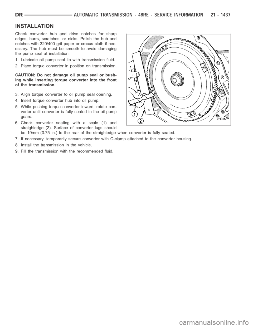
6. Check converter seating with a scale (1) and
straightedge (2). Surface of converter lugs should
be 19mm (0.75 in.) to the rear of the straightedge when converter is fully seated.
7. If necessary, temporarily secure converter with C-clamp attached to the converter housing.
8. Install the transmission in the vehicle.
9. Fill the transmission with the recommended fluid.
Page 3959 of 5267
VALVE-TORQUE CONVERTER DRAINBACK
DESCRIPTION
GAS ENGINES
The drainback valve is located in the transmission cooler outlet (pressure) line.
DIESEL ENGINE
The converter drainback check valve is located in the in the TOC pressure - supply line, between the engine
mounted TOC and the air to oil TOC.
OPERATION
GAS ENGINES
The valve prevents fluid from draining from the converter into the cooler and lines when the vehicle is shut down for
lengthy periods. Production valves have a hose nipple at one end, while theopposite end is threaded for a flare
fitting. All valves have an arrow (or similar mark) to indicate direction of flow through the valve.
DIESEL ENGINE
The valve prevents fluid from draining from the converter into the cooler and lines when the vehicle is shut down for
lengthy periods. Production valves have pipe thread on one end, while the opposite end is threaded for a flare
fitting, and are threaded into the oil cooler mounted on the side of the engine. All valves have an arrow (or similar
mark) to indicate direction of flow through the valve.
STANDARD PROCEDURE
GAS ENGINES
The converter drainback check valve is located in the cooler outlet (pressure) line near the radiator tank. The valve
prevents fluid drainback when the vehicle is parked for lengthy periods. The valve check ball is spring loaded and
has an opening pressure of approximately 2 psi.
The valve is serviced as an assembly; it is not repairable. Do not clean the valve if restricted, or contaminated by
sludge, or debris. If the valve fails, or if a transmission malfunction occurs that generates significant amounts of
sludge and/or clutch particles and metal shavings, the valve must be replaced.
If the valve is restricted, installed backwards, or in the wrong line, it will cause an transmission overheating condition
and possible transmission failure.
CAUTION: The drainback valve is a one-way flow device. It must be properly orientedintermsofflowdirec-
tion for the cooler to function properly. The valve must be installed in thepressure line. Otherwise flow will
be blocked and would cause an transmission overheating condition and eventual transmission failure.
DIESEL ENGINE
The converter drainback check valve is located in the in the TOC pressure - supply line, between the engine
mounted transmission oil cooler and the air to oil transmission oil cooler. The valve prevents fluid drainback when
the vehicle is parked for lengthy periods. The valve check ball is spring loaded and has an opening pressure of
approximately 2 psi.
The valve is serviced as an assembly; it is not repairable. Do not clean the valve if restricted, or contaminated by
sludge, or debris. If the valve fails, or if a transmission malfunction occurs that generates significant amounts of
sludge and/or clutch particles and metal shavings, the valve must be replaced.
If the valve is restricted, installed backwards, or in the wrong line, it will cause an transmission overheating condition
and possible transmission failure.
Page 4007 of 5267
sharpness of these edges is vitally important. The edges prevent foreign matter from lodging between the valves
and plugs and the bore.
Inspect all the valve and plug bores in the valve body. Use a penlight to viewthe bore interiors. Replace the valve
body if any bores are distorted or scored. Inspect all of the valve body springs. The springs must be free of dis-
tortion, warpage or broken coils.
Check the two separator plates for distortion or damage of any kind. Inspect the upper housing, lower housing, 3-4
accumulator housing, and transfer plate carefully. Be sure all fluid passages are clean and clear. Check condition of
the upper housing and transfer plate check balls as well. The check balls and ball seats must not be worn or dam-
aged.
Trial fit each valve and plug in its bore to check freedom of operation. Whenclean and dry, the valves and plugs
shoulddropfreelyintothebores.
Valve body bores do not change dimensionally with use. If the valve body functioned correctly when new, it will
continue to operate properly after cleaning and inspection. It should notbe necessary to replace a valve body
assembly unless it is damaged in handling.
The only serviceable valve body components are listed below. The remaining valve body components are serviced
only as part of a complete valve body assembly. Serviceable parts are:
dual solenoid and harness assembly
solenoid gasket
solenoid case connector O-rings and shoulder bolt
switch valve and spring
pressure adjusting screw and bracket assembly
throttle lever
manual lever and shaft seal
throttle lever shaft seal, washer, and E-clip
fluid filter and screws
detent ball and spring
valve body screws
governor pressure solenoid
governor pressure sensor and retaining clip
park lock rod and E-clip
ASSEMBLY
CAUTION: Do not force valves or plugs into place during reassembly. If the valve body bores, valves and
plugs are free of distortion or burrs, the valve body components should allslide into place easily. In addi-
tion, do not overtighten the transfer plate and valve body screws during reassembly. Overtightening can
distort the housings resulting in valve sticking, cross leakage and unsatisfactory operation. Tighten valve
body screws to recommended torque only.
Page 4018 of 5267
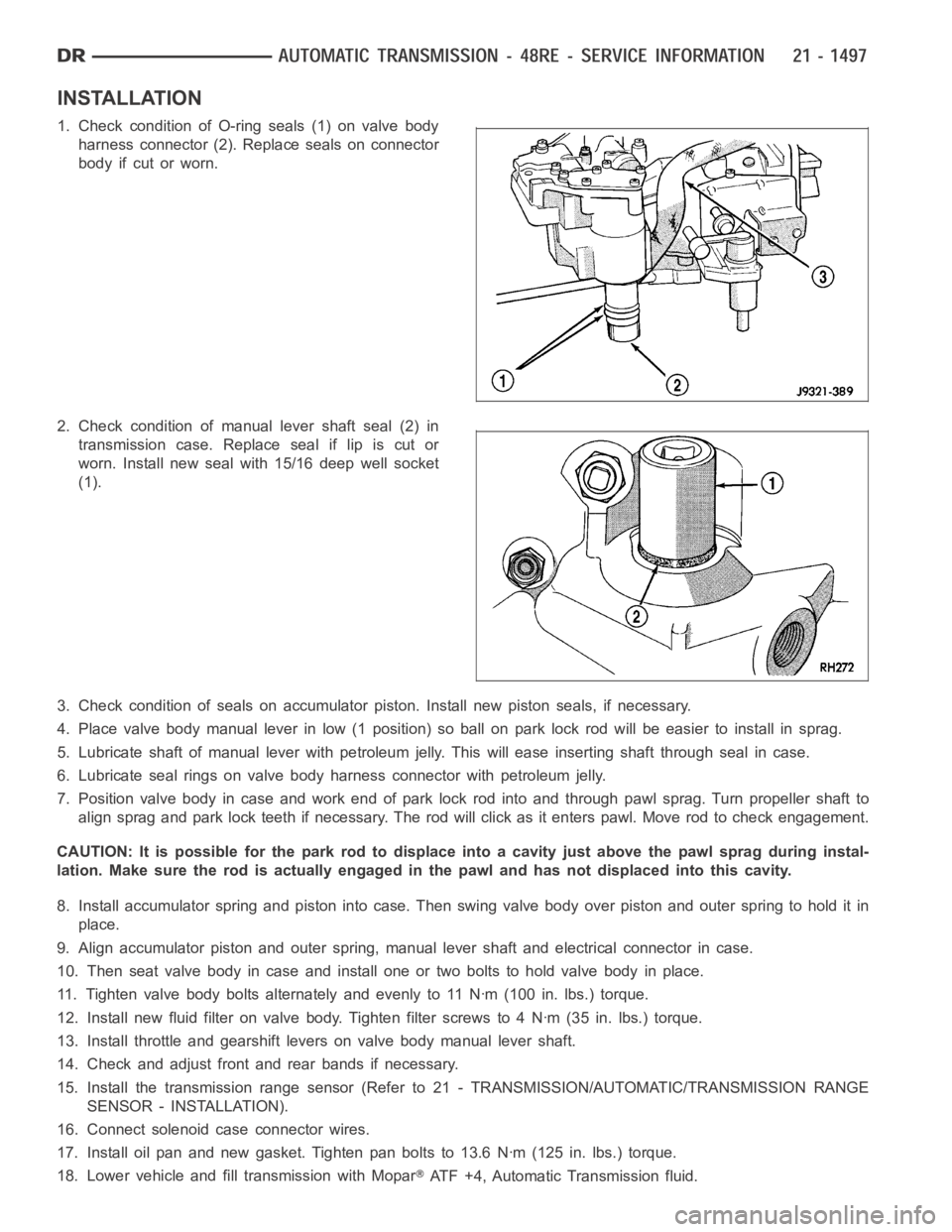
INSTALLATION
1. Check condition of O-ring seals (1) on valve body
harness connector (2). Replace seals on connector
body if cut or worn.
2. Check condition of manual lever shaft seal (2) in
transmission case. Replace seal if lip is cut or
worn. Install new seal with 15/16 deep well socket
(1).
3. Check condition of seals on accumulator piston. Install new piston seals, if necessary.
4. Place valve body manual lever in low (1 position) so ball on park lock rod will be easier to install in sprag.
5. Lubricate shaft of manual lever with petroleum jelly. This will ease inserting shaft through seal in case.
6. Lubricate seal rings on valve body harness connector with petroleum jelly.
7. Position valve body in case and work end of park lock rod into and through pawl sprag. Turn propeller shaft to
align sprag and park lock teeth if necessary. The rod will click as it enterspawl. Move rod to check engagement.
CAUTION: It is possible for the park rod to displace into a cavity just abovethe pawl sprag during instal-
lation. Make sure the rod is actually engaged in the pawl and has not displaced into this cavity.
8. Install accumulator spring and piston into case. Then swing valve body overpistonandouterspringtoholditin
place.
9. Align accumulator piston and outer spring, manual lever shaft and electrical connector in case.
10. Then seat valve body in case and install one or two bolts to hold valve bodyinplace.
11. Tighten valve body bolts alternately and evenly to 11 Nꞏm (100 in. lbs.)torque.
12. Install new fluid filter on valve body. Tighten filter screws to 4 Nꞏm (35 in. lbs.) torque.
13. Install throttle and gearshift levers on valve body manual lever shaft.
14. Check and adjust front and rear bands if necessary.
15. Install the transmission range sensor (Refer to 21 - TRANSMISSION/AUTOMATIC/TRANSMISSION RANGE
SENSOR - INSTALLATION).
16. Connect solenoid case connector wires.
17. Install oil pan and new gasket. Tighten pan bolts to 13.6 Nꞏm (125 in. lbs.) torque.
18. Lower vehicle and fill transmission with Mopar
ATF +4, Automatic Transmission fluid.
Page 4087 of 5267
Condition Possible Cause Correction
Lubricant leaking from output shaft
seal or vent.1) Transfer case overfilled. 1) Drain lubricant to the correct
level.
2) Vent closed or restricted. 2) Clear or replace vent as
necessary.
3) Output shaft seals damaged or
installed incorrectly.3) Replace seal as necessary.
Check to ensure that another
component, the propeller shaft slip
yoke for example, is not causing
damage to seal.
Abnormal tire wear. 1) Extended operation on hard, dry
surfaces in the 4H position.1) Operate vehicle in the 2H
position on hard, dry surfaces.
REMOVAL
1. Raise and support vehicle.
2. Remove skid plate, if equipped. (Refer to 13 - FRAMES & BUMPERS/FRAME/TRANSFER CASE SKID PLATE
- REMOVAL)
3. Position drain oil container under transfer case.
4. Remove transfer case drain plug and drain lubricant into container.
5. Disconnect vent hose and transfer case position sensor connector.
6. Disconnect shift rod from grommet in transfer case shift lever, or from floor shift arm whichever provides easy
access. Use channel lock style pliers to press rod out of lever grommet.
7. Support transmission with jack stand.
8. Mark front and rear propeller shafts for assembly reference.
9. Remove front and rear propeller shafts. (Refer to 3 - DIFFERENTIAL & DRIVELINE/PROPELLER SHAFT/PRO-
PELLER SHAFT - REMOVAL)
10. Support transfer case with suitable jack. Secure transfer case to jackwith safety chains.
11. Remove nuts attaching transfer case to transmission.
12. Move transfer case assembly rearward until free of transmission outputshaft.
13. Lower jack and move transfer case from under vehicle.
DISASSEMBLY
Position transfer case in a shallow drain pan. Remove drain plug and drain any remaining lubricant remaining in
case.
SHIFT LEVER AND FRONT OUTPUT SHAFT SEAL
1. Shift transfer case into NEUTRAL.
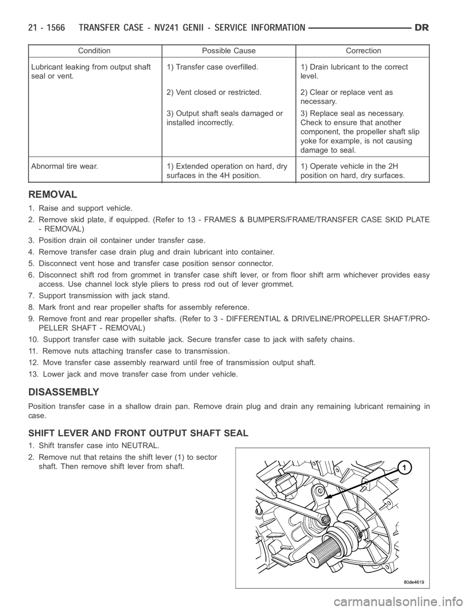
2. Remove nut that retains the shift lever (1) to sector
shaft. Then remove shift lever from shaft.
Page 4100 of 5267
INSPECTION
MAINSHAFT/SPROCKET/HUB
Inspect the splines on the hub and shaft and the teeth on the sprocket. Minornicks and scratches can be smoothed
with an oilstone, however, replace any part that is damaged.
Check the contact surfaces in the sprocket bore and on the mainshaft. Minornicks and scratches can be smoothed
with 320-400 grit emery cloth but do not try to salvage the shaft if nicks or wear is severe.
INPUT GEAR AND PLANETARY CARRIER
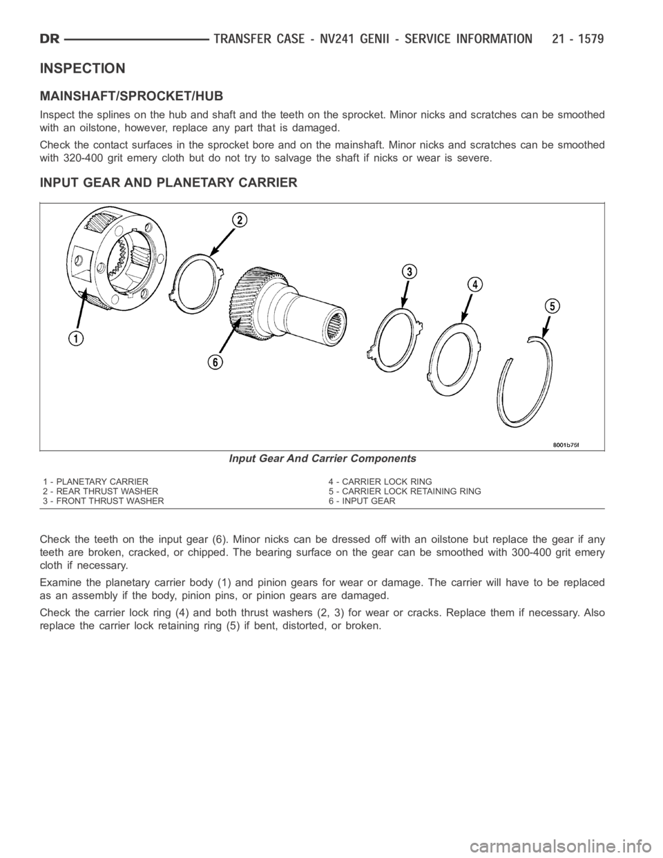
Check the teeth on the input gear (6). Minor nicks can be dressed off with an oilstone but replace the gear if any
teeth are broken, cracked, or chipped. The bearing surface on the gear can besmoothedwith300-400gritemery
cloth if necessary.
Examine the planetary carrier body (1) and pinion gears for wear or damage.The carrier will have to be replaced
as an assembly if the body, pinion pins, or pinion gears are damaged.
Check the carrier lock ring (4) and both thrust washers (2, 3) for wear or cracks. Replace them if necessary. Also
replace the carrier lock retaining ring (5) if bent, distorted, or broken.
Input Gear And Carrier Components
1 - PLANETARY CARRIER 4 - CARRIER LOCK RING
2 - REAR THRUST WASHER 5 - CARRIER LOCK RETAINING RING
3 - FRONT THRUST WASHER 6 - INPUT GEAR
Page 4102 of 5267
LOW RANGE ANNULUS GEAR
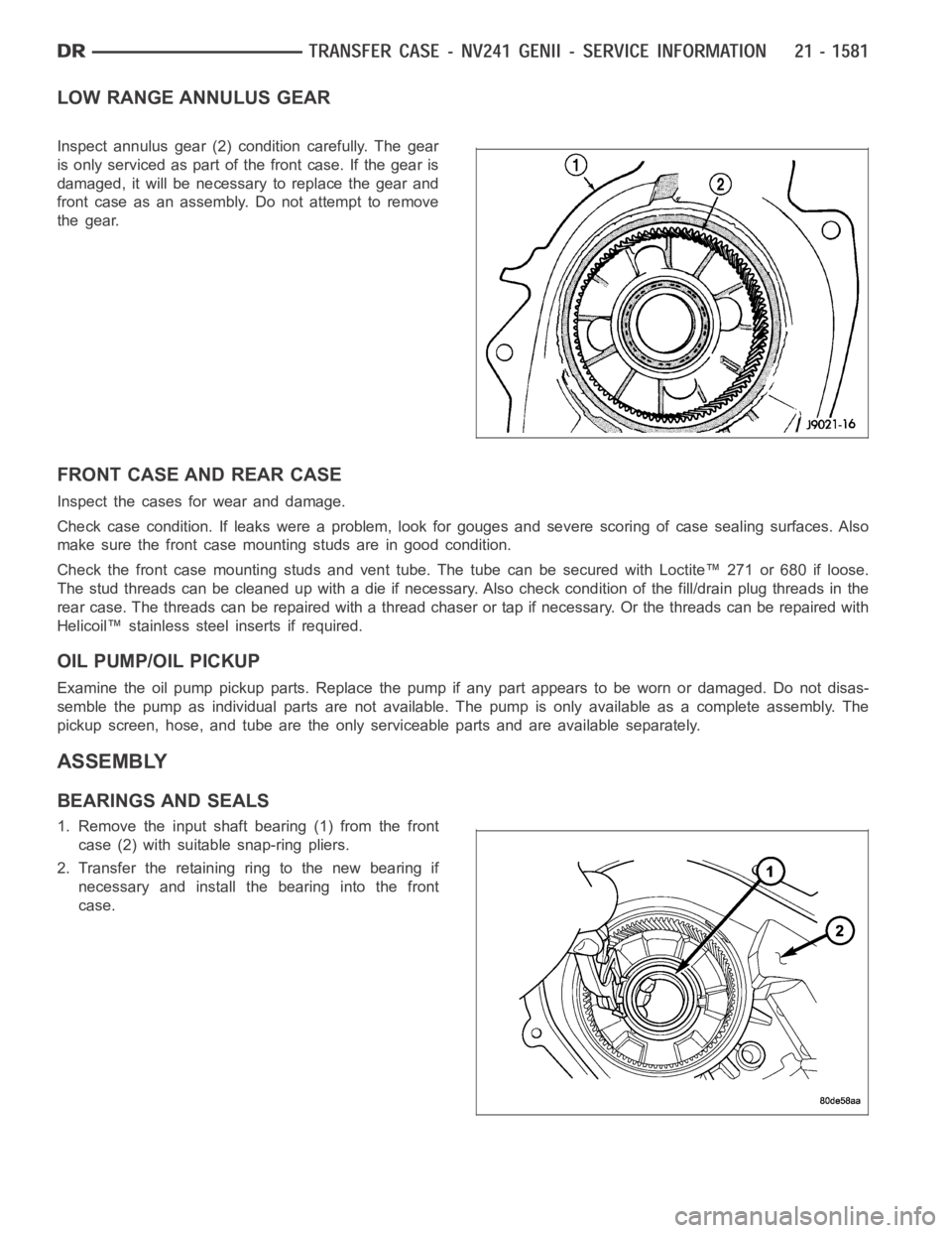
Inspect annulus gear (2) condition carefully. The gear
is only serviced as part of the front case. If the gear is
damaged, it will be necessary to replace the gear and
front case as an assembly. Do not attempt to remove
the gear.
FRONT CASE AND REAR CASE
Inspect the cases for wear and damage.
Check case condition. If leaks were a problem, look for gouges and severe scoring of case sealing surfaces. Also
make sure the front case mounting studs are in good condition.
Check the front case mounting studs and vent tube. The tube can be secured with Loctite™ 271 or 680 if loose.
Thestudthreadscanbecleanedupwithadieifnecessary.Alsocheckcondition of the fill/drain plug threads in the
rear case. The threads can be repaired with a thread chaser or tap if necessary. Or the threads can be repaired with
Helicoil™ stainless steel inserts if required.
OIL PUMP/OIL PICKUP
Examine the oil pump pickup parts. Replace the pump if any part appears to beworn or damaged. Do not disas-
semble the pump as individual parts are not available. The pump is only available as a complete assembly. The
pickup screen, hose, and tube are the only serviceable parts and are available separately.
ASSEMBLY
BEARINGS AND SEALS
1. Remove the input shaft bearing (1) from the front
case (2) with suitable snap-ring pliers.
2. Transfer the retaining ring to the new bearing if
necessary and install the bearing into the front
case.