2006 DODGE RAM SRT-10 check oil
[x] Cancel search: check oilPage 4237 of 5267
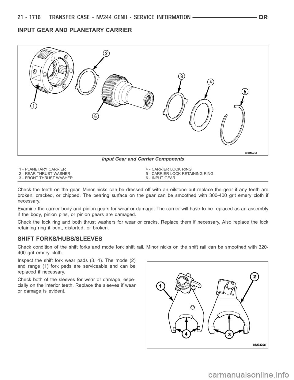
INPUT GEAR AND PLANETARY CARRIER
Check the teeth on the gear. Minor nicks can be dressed off with an oilstone but replace the gear if any teeth are
broken, cracked, or chipped. The bearing surface on the gear can be smoothed with 300-400 grit emery cloth if
necessary.
Examine the carrier body and pinion gears for wear or damage. The carrier will have to be replaced as an assembly
if the body, pinion pins, or pinion gears are damaged.
Check the lock ring and both thrust washers for wear or cracks. Replace themif necessary. Also replace the lock
retaining ring if bent, distorted, or broken.
SHIFT FORKS/HUBS/SLEEVES
Check condition of the shift forks and mode fork shift rail. Minor nicks on the shift rail can be smoothed with 320-
400 grit emery cloth.
Inspect the shift fork wear pads (3, 4). The mode (2)
and range (1) fork pads are serviceable and can be
replaced if necessary.
Check both of the sleeves for wear or damage, espe-
cially on the interior teeth. Replace the sleeves if wear
or damage is evident.
Input Gear and Carrier Components
1 - PLANETARY CARRIER 4 - CARRIER LOCK RING
2 - REAR THRUST WASHER 5 - CARRIER LOCK RETAINING RING
3 - FRONT THRUST WASHER 6 - INPUT GEAR
Page 4238 of 5267
REAR EXTENSION HOUSING
Inspect the extension housing seal and bushing. Replace both components if either show any sign of wear or dam-
age.
FRONT OUTPUT SHAFT AND DRIVE CHAIN
Inspect the shaft splines and bearing surfaces. Minor nicks on the splinescanbesmoothedwithanoilstone.Use
320-400 grit emery to smooth minor scratches on the shaft bearing surfaces. Replace the shaft if the bearing sur-
faces are scored or if any of the splines are cracked or broken.
Examine the drive chain and shaft bearings. Replace the chain and both sprockets if the chain is stretched, dis-
torted, or if any of the links bind. Replace the bearings if rough, or noisy.
LOW RANGE ANNULUS GEAR
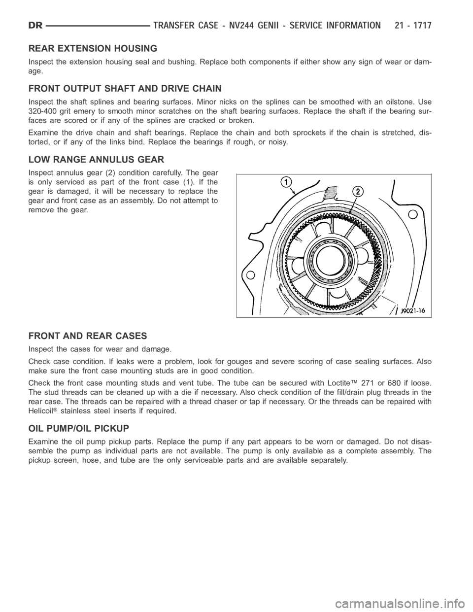
Inspect annulus gear (2) condition carefully. The gear
is only serviced as part of the front case (1). If the
gear is damaged, it will be necessary to replace the
gear and front case as an assembly. Do not attempt to
remove the gear.
FRONT AND REAR CASES
Inspect the cases for wear and damage.
Check case condition. If leaks were a problem, look for gouges and severe scoring of case sealing surfaces. Also
make sure the front case mounting studs are in good condition.
Check the front case mounting studs and vent tube. The tube can be secured with Loctite™ 271 or 680 if loose.
Thestudthreadscanbecleanedupwithadieifnecessary.Alsocheckcondition of the fill/drain plug threads in the
rear case. The threads can be repaired with a thread chaser or tap if necessary. Or the threads can be repaired with
Helicoil
stainless steel inserts if required.
OIL PUMP/OIL PICKUP
Examine the oil pump pickup parts. Replace the pump if any part appears to beworn or damaged. Do not disas-
semble the pump as individual parts are not available. The pump is only available as a complete assembly. The
pickup screen, hose, and tube are the only serviceable parts and are available separately.
Page 4281 of 5267
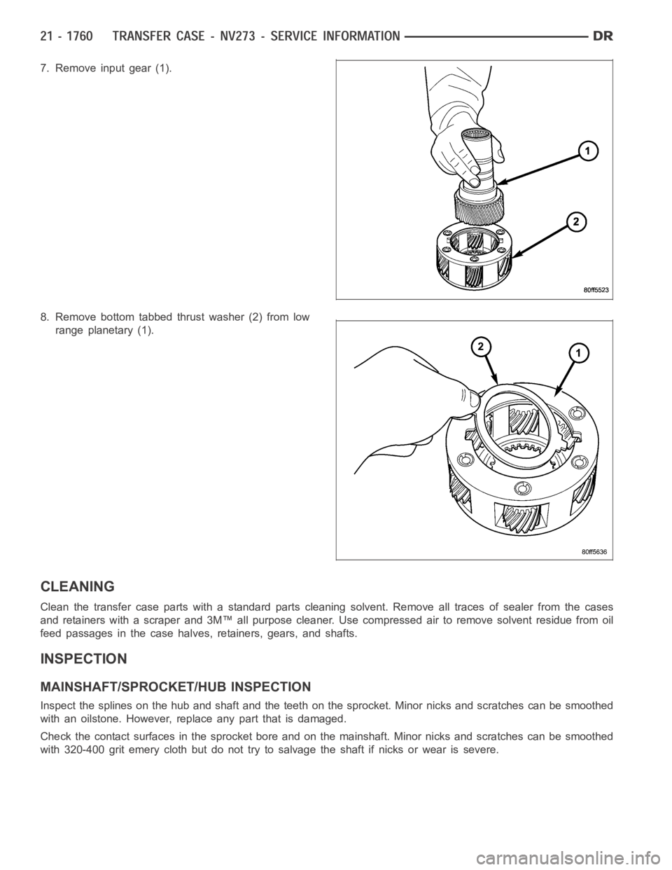
7. Remove input gear (1).
8. Remove bottom tabbed thrust washer (2) from low
range planetary (1).
CLEANING
Clean the transfer case parts with a standard parts cleaning solvent. Remove all traces of sealer from the cases
and retainers with a scraper and 3M™ all purpose cleaner. Use compressed air to remove solvent residue from oil
feed passages in the case halves, retainers, gears, and shafts.
INSPECTION
MAINSHAFT/SPROCKET/HUB INSPECTION
Inspect the splines on the hub and shaft and the teeth on the sprocket. Minornicks and scratches can be smoothed
with an oilstone. However, replace any part that is damaged.
Check the contact surfaces in the sprocket bore and on the mainshaft. Minornicks and scratches can be smoothed
with 320-400 grit emery cloth but do not try to salvage the shaft if nicks or wear is severe.
Page 4282 of 5267
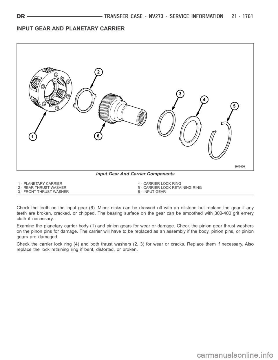
INPUT GEAR AND PLANETARY CARRIER
Check the teeth on the input gear (6). Minor nicks can be dressed off with an oilstone but replace the gear if any
teeth are broken, cracked, or chipped. The bearing surface on the gear can besmoothedwith300-400gritemery
cloth if necessary.
Examine the planetary carrier body (1) and pinion gears for wear or damage.Check the pinion gear thrust washers
on the pinon pins for damage. The carrier will have to be replaced as an assembly if the body, pinion pins, or pinion
gears are damaged.
Check the carrier lock ring (4) and both thrust washers (2, 3) for wear or cracks. Replace them if necessary. Also
replace the lock retaining ring if bent, distorted, or broken.
Input Gear And Carrier Components
1 - PLANETARY CARRIER 4 - CARRIER LOCK RING
2 - REAR THRUST WASHER 5 - CARRIER LOCK RETAINING RING
3 - FRONT THRUST WASHER 6 - INPUT GEAR
Page 4283 of 5267
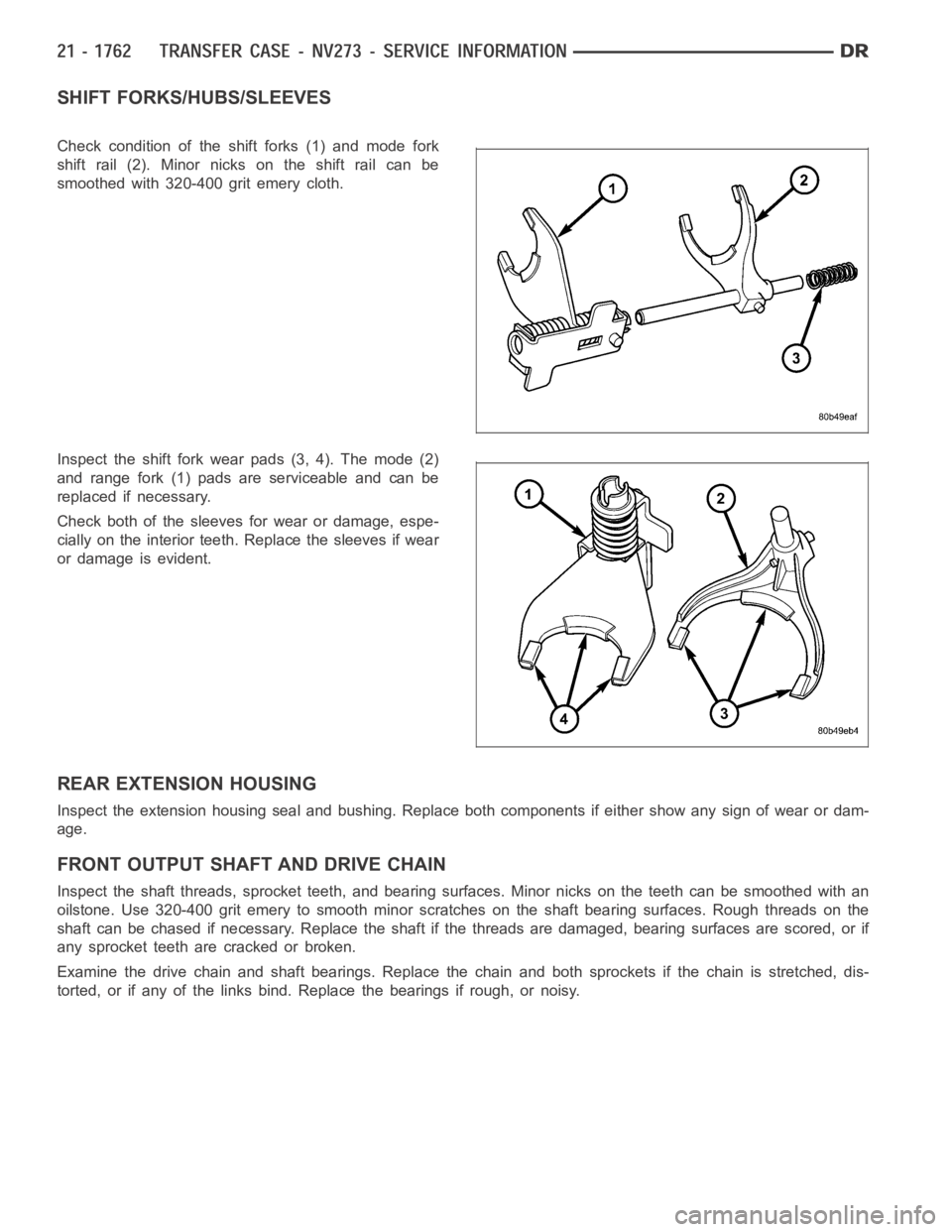
SHIFT FORKS/HUBS/SLEEVES
Check condition of the shift forks (1) and mode fork
shift rail (2). Minor nicks on the shift rail can be
smoothed with 320-400 grit emery cloth.
Inspect the shift fork wear pads (3, 4). The mode (2)
and range fork (1) pads are serviceable and can be
replaced if necessary.
Check both of the sleeves for wear or damage, espe-
cially on the interior teeth. Replace the sleeves if wear
or damage is evident.
REAR EXTENSION HOUSING
Inspect the extension housing seal and bushing. Replace both components if either show any sign of wear or dam-
age.
FRONT OUTPUT SHAFT AND DRIVE CHAIN
Inspect the shaft threads, sprocket teeth, and bearing surfaces. Minor nicksontheteethcanbesmoothedwithan
oilstone. Use 320-400 grit emery to smooth minor scratches on the shaft bearing surfaces. Rough threads on the
shaft can be chased if necessary. Replace the shaft if the threads are damaged, bearing surfaces are scored, or if
any sprocket teeth are cracked or broken.
Examine the drive chain and shaft bearings. Replace the chain and both sprockets if the chain is stretched, dis-
torted, or if any of the links bind. Replace the bearings if rough, or noisy.
Page 4284 of 5267
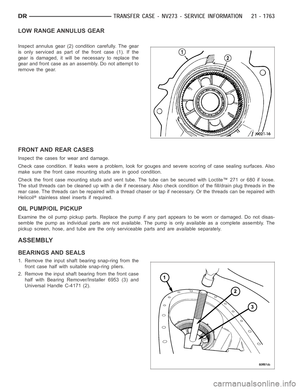
LOW RANGE ANNULUS GEAR
Inspect annulus gear (2) condition carefully. The gear
is only serviced as part of the front case (1). If the
gear is damaged, it will be necessary to replace the
gear and front case as an assembly. Do not attempt to
remove the gear.
FRONT AND REAR CASES
Inspect the cases for wear and damage.
Check case condition. If leaks were a problem, look for gouges and severe scoring of case sealing surfaces. Also
make sure the front case mounting studs are in good condition.
Check the front case mounting studs and vent tube. The tube can be secured with Loctite™ 271 or 680 if loose.
Thestudthreadscanbecleanedupwithadieifnecessary.Alsocheckcondition of the fill/drain plug threads in the
rear case. The threads can be repaired with a thread chaser or tap if necessary. Or the threads can be repaired with
Helicoil
stainless steel inserts if required.
OIL PUMP/OIL PICKUP
Examine the oil pump pickup parts. Replace the pump if any part appears to beworn or damaged. Do not disas-
semble the pump as individual parts are not available. The pump is only available as a complete assembly. The
pickup screen, hose, and tube are the only serviceable parts and are available separately.
ASSEMBLY
BEARINGS AND SEALS
1. Remove the input shaft bearing snap-ring from the
front case half with suitable snap-ring pliers.
2. Remove the input shaft bearing from the front case
half with Bearing Remover/Installer 6953 (3) and
Universal Handle C-4171 (2).
Page 5053 of 5267
ACTUATOR DTC DETECTION TEST — DUAL-ZONE
The Actuator DTC Detection Test:
is actuated with a scan tool.
clears all actuator related DTCs when the test is actuated.
supplements the continuous diagnostics on the actuator drive system.
monitors for shorted actuator circuits allowing service to easily diagnose and troubleshoot up to three simul-
taneous shorts. Shorted actuator circuit faults (XXX Control Circuit High or XXX Control Circuit Low) will only
display after running the Actuator DTC Detection Test.
After repairing each DTC, cycle the ignition switch, and then run the Actuator DTC Detection Test again to ensure
that no new DTCs exist. If multiple DTCs are present, beginning with the passenger blend door, diagnose and repair
all short high faults and then short low faults. When the test returns passed, clear all faults and run the Actuator
Calibration function as a final check of system health.
ACTUATOR DTC DETECTION TEST — SINGLE-ZONE
The Actuator DTC Detection Test:
is actuated with a scan tool.
clears all actuator related DTCs when the test is actuated.
supplements the continuous diagnostics on the actuator drive system.
monitors for shorted actuator circuits allowing service to easily diagnose and troubleshoot up to three simul-
taneous shorts. Shorted actuator circuit faults (XXX Control Circuit High or XXX Control Circuit Low) will only
display after running the Actuator DTC Detection Test.
After repairing each DTC, cycle the ignition switch, and then run the Actuator DTC Detection Test again to ensure
that no new DTCs exist. If multiple DTCs are present, beginning with the common circuit, diagnose and repair all
short high faults and then short low faults. When the test returns passed, clear all faults and run the Actuator Cal-
ibration function as a final check of system health.
A/C PERFORMANCE
The A/C system is designed to provide the passenger compartment with low temperature and low humidity air. The
A/C evaporator, located in the HVAC housing is cooled to temperatures nearthe freezing point. As warm damp air
passes over the fins of the A/C evaporator, the air transfers its heat to therefrigerant in the evaporator coils and the
moisture in the air condenses on the evaporator fins. During periods of high heat and humidity, an A/C system will
be more effective in the Recirculation mode (max-A/C). With the system in the Recirculation mode, only air from the
passenger compartment passes through the A/C evaporator. As the passenger compartment air dehumidifies, the
A/C system performance levels rise.
Humidity has an important bearing on the temperature of the air delivered to the interior of the vehicle. It is impor-
tant to understand the effect that humidity has on the performance of the A/C system. When humidity is high, the
A/C evaporator has to perform a double duty. It must lower the air temperature, and it must lower the temperature
of the moisture in the air that condenses on the evaporator fins. Condensing the moisture in the air transfers heat
energy into the evaporator fins and coils. This reduces the amount of heat the A/C evaporator can absorb from the
air. High humidity greatly reduces the ability of the A/C evaporator to lower the temperature of the air.
However, evaporator capacity used to reduce the amount of moisture in the air is not wasted. Wringing some of the
moisture out of the air entering the vehicle adds to the comfort of the passengers. Although, an owner may expect
too much from their A/C system on humid days. A performance test is the best way to determine whether the sys-
tem is performing up to design standards. This test also provides valuableclues as to the possible cause of trouble
with the A/C system. The ambient air temperature in the location where the vehicle will be tested must be a mini-
mum of 21° C (70° F) for this test.
A/C PERFORMANCE TEST
WARNING: Refer to the applicable warnings and cautions for this system before performing the following
operation (Refer to 24 - HEATING & AIR CONDITIONING/PLUMBING - WARNINGS) and (Refer to 24 - HEAT-
ING & AIR CONDITIONING/PLUMBING - CAUTIONS). Failure to follow the warnings and cautions could result
in possible personal injury or death.
Page 5055 of 5267
Condition Possible Causes Correction
2. Faulty fuse.2. Check the fuse in the junction block. Repair the
shorted circuit or component and replace the fuse,
if required.
3. Faulty A/C compressor
clutch field coil.3. See A/C Compressor Clutch Field Coil in this
group. Test the compressor clutch field coil and
replace, if required.
4. Improperly installed or
faulty Evaporator
Temperature Sensor.4. See Evaporator Temperature Sensor in this
group. Correctly install or replace the sensor as
required.
5. Faulty A/C pressure
transducer.5. See A/C pressure transducer in this group. Test
the transducer and replace, if required.
6. Faulty A/C-heater control,
totally integrated power
module (TIPM), gateway
module or PCM/ECM.6. Refer to the appropriate Electrical Diagnostic
Procedures for testing of the A/C-heater control,
TIPM, gateway module or PCM/ECM. Test the
module and replace, if required.
Normal pressures, but A/C
Performance Test air
temperatures at center panel
outlet are too high.1. Excessive refrigerant oil in
system.1. See Refrigerant Oil Level in this group. Recover
the refrigerant from the refrigerant system and
inspect the refrigerant oil content. Restore the
refrigerant oil to the proper level, if required.
2. Blend door inoperative or
sealing improperly.2. See Blend Door in this group. Inspect the blend
door for proper operation and sealing and correct,
if required.
3. Blend door actuator faulty
or inoperative.3. Perform blend door actuator diagnosis, replace
if faulty.
The low side pressure is
normal or slightly low, and
the high side pressure is too
low.1. Low refrigerant system
charge.1. See Refrigerant System Leaks in this group.
Test the refrigerant system for leaks. Repair,
evacuate and charge the refrigerant system, if
required.
2. Refrigerant flow through
the accumulator is restricted.2. See Accumulator in this group. Replace the
restricted accumulator, if required.
3. Refrigerant flow through
the evaporator coil is
restricted.3. See A/C Evaporator in this group. Replace the
restricted evaporator coil, if required.
4. Faulty compressor.4. See A/C Compressor in this group. Replace the
compressor, if required.
The low side pressure is
normal or slightly high, and
the high side pressure is too
high.1. Condenser air flow
restricted.1. Check the A/C condenser for damaged fins,
foreign objects obstructing air flow through the
condenser fins, and missing or improperly
installed air seals. Refer to Cooling for more
information on air seals. Clean, repair, or replace
components as required.
2. Inoperative cooling fan.2. Refer to Cooling for more information. Test the
cooling fan and replace, if required.
3. Refrigerant system
overcharged.3. See Refrigerant System Charge in this group.
Recover the refrigerant from the refrigerant
system. Charge the refrigerant system to the
proper level, if required.
4. Air in the refrigerant
system.4. See Refrigerant System Leaks in this group.
Test the refrigerant system for leaks. Repair,
evacuate and charge the refrigerant system, if
required.