Page 2138 of 5267

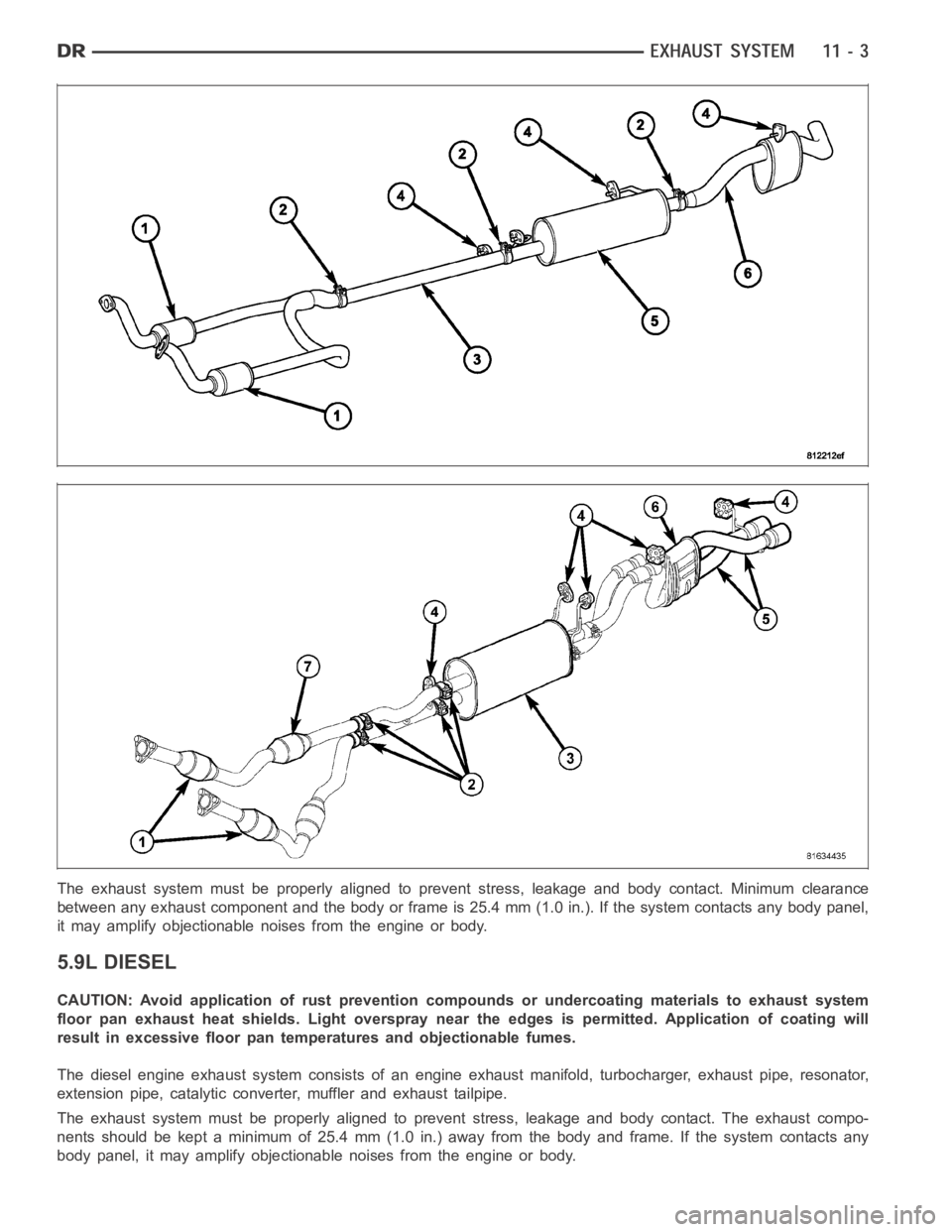
The exhaust system must be properly aligned to prevent stress, leakage andbody contact. Minimum clearance
between any exhaust component and the body or frame is 25.4 mm (1.0 in.). If the system contacts any body panel,
it may amplify objectionable noises from the engine or body.
5.9L DIESEL
CAUTION: Avoid application of rust prevention compounds or undercoatingmaterials to exhaust system
floor pan exhaust heat shields. Light overspray near the edges is permitted. Application of coating will
result in excessive floor pan temperatures and objectionable fumes.
The diesel engine exhaust system consists of an engine exhaust manifold, turbocharger, exhaust pipe, resonator,
extension pipe, catalytic converter, muffler and exhaust tailpipe.
The exhaust system must be properly aligned to prevent stress, leakage andbody contact. The exhaust compo-
nents should be kept a minimum of 25.4 mm (1.0 in.) away from the body and frame. If the system contacts any
body panel, it may amplify objectionable noises from the engine or body.
Page 2171 of 5267

CLEANING
CAUTION: Do not use caustic cleaners to clean the charge air cooler. Damageto the charge air cooler will
result.
NOTE: If internal debris cannot be removed from the cooler, the charge air cooler MUST be replaced.
1. If the engine experiences a turbocharger failure or any other situationwhere oil or debris get into the charge air
cooler, the charge air cooler must be cleaned internally.
2. Position the charge air cooler so the inlet and outlet tubes are vertical.
3. Flush the cooler internally with solvent in the direction opposite of normal air flow.
4. Shake the cooler and lightly tap on the end tanks with a rubber mallet to dislodge trapped debris.
5. Continue flushing until all debris or oil are removed.
6. Rinse the cooler with hot soapy water to remove any remaining solvent.
7. Rinse thoroughly with clean water and blow dry with compressed air.
INSPECTION
Visually inspect the charge air cooler for cracks, holes, or damage. Inspect the tubes, fins, and welds for tears,
breaks, or other damage. Replace the charge air cooler if damage is found.
Pressure test the charge air cooler, using Charge Air Cooler Tester Kit No.3824556. This kit is available through
Cummins
Service Products. Instructions are provided with the kit.
INSTALLATION
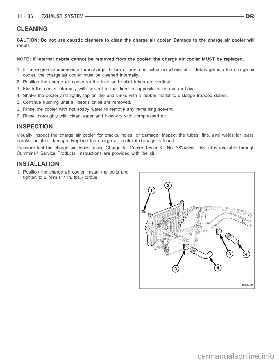
1. Position the charge air cooler. Install the bolts and
tighten to 2 Nꞏm (17 in. lbs.) torque.
Page 2180 of 5267
REAR BUMPER
REMOVAL
1. Raise and support the vehicle (Refer to LUBRICA-
TION & MAINTENANCE/HOISTING - STANDARD
PROCEDURE).
2. Remove the license plate.
3. Remove the bolts behind the plate.
4. Disconnect the license plate light electrical connec-
tors.
5. Disconnect the trailer light connector electrical con-
nection (if equipped).
6. Remove the two bolts along the front upper edge
of the bumper near the frame tips.
7. Support the bumper with a suitable lifting device.
8. Remove the bolts attaching the bumper support
brackets (4) to the trailer hitch (1).
Page 2181 of 5267
INSTALLATION
1. Align the holes in the bumpers to the trailer hitch
pins and install the bumper.
2. Loosely install the hitch bolts (2) in the support
bracket (4).
3. Install the front upper edge to the trailer hitch bolts
(2)andtightento54Nꞏm(40ft.lbs.).
4. Install the license plate reinforcement to hitch bolts
(2)andtightento54Nꞏm(40ft.lbs.).
5. Tighten the left bumper bracket bolts (3) to 54 Nꞏm
(40 ft. lbs.).
6. Tighten the right bumper bracket bolts (3) to 54
Nꞏm (40 ft. lbs.).
7. Connect the trailer light connector electrical con-
nection (if equipped).
8. Connect the license plate light electrical connec-
tors.
9. Install the license plate.
Page 2194 of 5267
11. Remove the upper radiator crossmember (4). (Refer to 23 - BODY/EXTERIOR/UPPER RADIATOR CROSS-
MEMBER - REMOVAL).
12. Remove the headlamp unit (5) (Refer to 8 -
ELECTRICAL/LAMPS/LIGHTING - EXTERIOR/
HEADLAMP UNIT - REMOVAL).
Page 2197 of 5267
27. Install the front cab mount bolt (2) if previously removed and tighten to81Nꞏm(60ft.lbs.).
28. Install the lower radiator crossmember (6) bolts (5) and tighten to 28 Nꞏm ( 2 1 f t . l b s . ) .
29. Install the headlamp unit (Refer to 8 - ELECTRI-
CAL/LAMPS/LIGHTING - EXTERIOR/HEADLAMP
UNIT - INSTALLATION).
Page 2218 of 5267
TORQUE
TORQUE SPECIFICATIONS
DESCRIPTION Nꞏm Ft. Lbs.
Cab mount bolts 81 60
Cargo box bolts 108 80
Front crossmember bolts - 2WD (light duty only) 61 45
Front crossmember bolts - 2WD (heavy duty only) 75 55
Front crossmember bolts - 4WD (light duty only) 102 75
Front skid plate bolts 34 25
Lower bumper support bracket bolt 54 40
Radiator crossmember bolts - lower 28 21
Radiator crossmember bolts - upper 28 21
Rear crossmember (light duty only) 102 75
Rear crossmember (heavy duty only) 115 85
Rear spring shackle bolts 163 120
Sparetirewinchbolts 41 30
Trailer hitch reinforcement bracket bolt 170 125
Transfercase skid plate bolts 34 25
Transercase skid plate crossmember bolts 34 25
Transmission mount to crossmember nuts 54 40
Page 2221 of 5267
INSTALLATION
1. Install the crossmember (1).
2. Install the bolts (2);
On light duty 2WD vehicles, tighten the bolts to
61 Nꞏm (45 ft. lbs.).
On heavy duty 2WD vehicles, tighten the bolts to
75 Nꞏm (55 ft. lbs.).
3. On 4WD models, install the crossmember (2).
4. Install the bolts (1) and tighten to 102 Nꞏm (75 ft.
lbs.).
5. Remove all OEM e-coat within 51 mm (2.0 in.) of
the weld on both the crossmember and the frame.
CAUTION: Shield the surrounding area and com-
ponents from exposure to the welding spatter and
heat.
6. Using the Weld Process Specifications table (Refer
to 13 - FRAME & BUMPERS/FRAME - SPECIFI-
CATIONS - WELDING), apply new welds to the
SRT-10 crossmember.
NOTE: Any burned surface coatings will need to
be removed prior to application of corrosion pre-
ventative coatings.
7. Dress the welded area and apply corrosion resis-
tant coatings.
a. Apply etch-primer to the repair area.
b. Apply a durable top coat to the outside of the repair area.