Page 2371 of 5267

MODULE - FUEL TANK
DESCRIPTION
.
The fuel tank module is installed in the top of the fuel tank. The fuel tank module contains the following compo-
nents:
An electric fuel transfer (lift) pump
Fuel reservoir
A separate in-tank fuel filter
Fuel gauge sending unit (fuel level sensor)
Fuel supply line connection
A special lockring to retain module to fuel tank
Fuel return line connection
OPERATION
Refer to Fuel Gauge Sending Unit.
REMOVAL
1. Drain and remove fuel tank (Refer to 14 - FUEL
SYSTEM/FUEL DELIVERY/FUEL TANK -
REMOVAL).
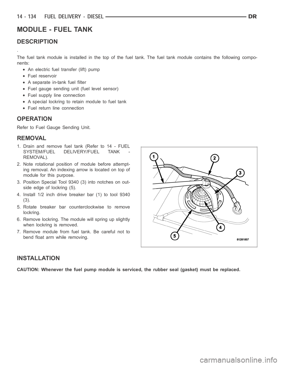
2. Note rotational position of module before attempt-
ing removal. An indexing arrow is located on top of
module for this purpose.
3. Position Special Tool 9340 (3) into notches on out-
side edge of lockring (5).
4. Install 1/2 inch drive breaker bar (1) to tool 9340
(3).
5. Rotate breaker bar counterclockwise to remove
lockring.
6. Remove lockring. The module will spring up slightly
when lockring is removed.
7. Remove module from fuel tank. Be careful not to
bend float arm while removing.
INSTALLATION
CAUTION: Whenever the fuel pump module is serviced, the rubber seal (gasket) must be replaced.
Page 2381 of 5267
INSTALLATION
1. Clean out machined hole in back of timing gear
housing.
2. Apply a small amount of engine oil to sensor O-ring
and sensor hole.
3. Install sensor into timing gear housing with a slight
rocking action. Do not twist sensor into position as
damagetoO-ringmayresult.
CAUTION: Before tightening sensor mounting bolt,
be sure sensor is completely flush to back of tim-
ing gear housing (cover). Remove (cover) if sensor
is not flush, damage to sensor mounting tang may
result.
4. Install mounting bolt and tighten. Torque to 9 Nꞏm
(80 in. lbs.).
5. Connect electrical connector (5) to sensor.
Page 2391 of 5267

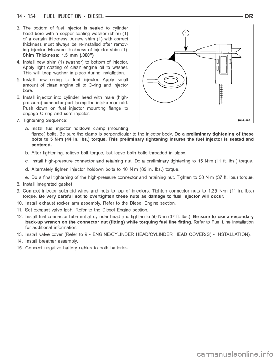
3. The bottom of fuel injector is sealed to cylinder
head bore with a copper sealing washer (shim) (1)
of a certain thickness. A new shim (1) with correct
thickness must always be re-installed after remov-
ing injector. Measure thickness of injector shim (1).
Shim Thickness: 1.5 mm (.060”)
4. Install new shim (1) (washer) to bottom of injector.
Apply light coating of clean engine oil to washer.
This will keep washer in place during installation.
5. Install new o-ring to fuel injector. Apply small
amount of clean engine oil to O-ring and injector
bore.
6. Install injector into cylinder head with male (high-
pressure) connector port facing the intake manifold.
Push down on fuel injector mounting flange to
engage O-ring and seat injector.
7. Tightening Sequence:
a. Install fuel injector holdown clamp (mounting
flange) bolts. Be sure the clamp is perpendicular to the injector body.Do a preliminary tightening of these
bolts to 5 Nꞏm (44 in. lbs.) torque. This preliminary tightening insures the fuel injector is seated and
centered.
b. After tightening, relieve bolt torque, but leave both bolts threaded inplace.
c. Install high-pressure connector and retaining nut. Do a preliminary tightening to 15 Nꞏm (11 ft. lbs.) torque.
d. Alternately tighten injector holdown bolts to 10 Nꞏm (89 in. lbs.) torque.
e. Do a final tightening of the high-pressure connector and retaining nut.Tighten to 50 Nꞏm (37 ft. lbs.) torque.
8. Install integrated gasket
9. Connect injector solenoid wires and nuts to top of injectors. Tighten connector nuts to 1.25 Nꞏm (11 in. lbs.)
torque.Be very careful not to overtighten these nuts as damage to fuel injector willoccur.
10. Install exhaust rocker arm assembly. Refer to the Diesel Engine section.
11. Set exhaust valve lash. Refer to the Diesel Engine section.
12. Install fuel connector tube nut at cylinder head and tighten to 50 Nꞏm (37ft.lbs.).Be sure to use a secondary
back-up wrench on the connector nut (fitting) while torquing fuel line fitting.Refer to Fuel Line Installation
for additional information.
13. Install valve cover (Refer to 9 - ENGINE/CYLINDER HEAD/CYLINDER HEAD COVER(S) - INSTALLATION).
14. Install breather assembly.
15. Connect negative battery cables to both batteries.
Page 2396 of 5267
INSTALLATION
1. Check condition of sensor O-ring.
2. Position sensor into top of air cleaner cover with a
slight twisting action.
3. Install 2 mounting screws (3).
4. Install electrical connector (2).
Page 2416 of 5267
8. Remove the clock spring, (Refer to 8 - ELECTRI-
CAL/RESTRAINTS/CLOCKSPRING - REMOVAL).
9. Disconnect the wiring harness (8) to the column.
10. Remove the shift cable (5) from the column shift
lever actuator (4) (Refer to 21 - TRANSMISSION/
TRANSAXLE/AUTOMATIC - 32RH/GEAR SHIFT
CABLE - REMOVAL).
11. Release the shift cable (5) from the column
bracket (7) and remove it from the bracket.
12. Remove the upper steering shaft coupler bolt (2).
13. Separate the shaft from the coupler (3).
14. Remove the brake light switch (2) and discard
(Refer to 8 - ELECTRICAL/LAMPS/LIGHTING -
EXTERIOR/BRAKE LAMP SWITCH - REMOVAL).
15. Remove the four steering column mounting nuts
(1 & 3).
Page 2417 of 5267

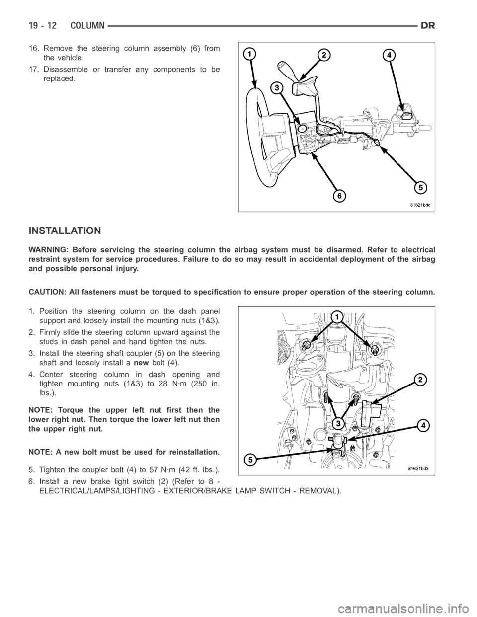
16. Remove the steering column assembly (6) from
the vehicle.
17. Disassemble or transfer any components to be
replaced.
INSTALLATION
WARNING: Before servicing the steering column the airbag system must be disarmed. Refer to electrical
restraint system for service procedures. Failure to do so may result in accidental deployment of the airbag
and possible personal injury.
CAUTION: All fasteners must be torqued to specification to ensure proper operation of the steering column.
1. Position the steering column on the dash panel
support and loosely install the mounting nuts (1&3).
2. Firmly slide the steering column upward against the
studs in dash panel and hand tighten the nuts.
3. Install the steering shaft coupler (5) on the steering
shaft and loosely install anewbolt (4).
4. Center steering column in dash opening and
tighten mounting nuts (1&3) to 28 Nꞏm (250 in.
lbs.).
NOTE: Torque the upper left nut first then the
lower right nut. Then torque the lower left nut then
the upper right nut.
NOTE: A new bolt must be used for reinstallation.
5. Tighten the coupler bolt (4) to 57 Nꞏm (42 ft. lbs.).
6. Install a new brake light switch (2) (Refer to 8 -
ELECTRICAL/LAMPS/LIGHTING - EXTERIOR/BRAKE LAMP SWITCH - REMOVAL).
Page 2419 of 5267
15. Install the steering column opening cover (1) and
kneeblocker (2) (Refer to 23 - BODY/INSTRU-
MENT PANEL/STEERING COLUMN OPENING
COVER - INSTALLATION).
16. Install the negative battery terminal.
17. Test the operation of the horn, Electronic PRNDL
Indicator, lights and any other functions that are
steering column operated.
SPECIFICATIONS
TORQUE
TORQUE SPECIFICATIONS
DESCRIPTION Nꞏm Ft. Lbs. In. Lbs.
Steering Coupling Upper
Pinch Bolt
LD & HD57 42 —
Steering Coupling Upper
Pinch Bolt
4X4 HD57 42 –
Steering Coupling Lower
Pinch Bolt
LD & HD57 42 —
Steering Coupling Lower
Pinch Bolt
SRT1038 28 —
Steering Coupling Lower
Pinch Bolt
4X4 HD28 21 250
Steering Wheel Bolt 61 45 —
Ignitiion Switch Mounting
Screws3—26
Tilt Lever Release
Mounting Screws4.5 — 40
Page 2487 of 5267

FLUID
DESCRIPTION
NOTE: It is normal that some pressure will build up inside the reservoir, especially, with a warm vehicle. A
slight popping noise upon removal ofthe cap is normal. The fluid level should read between the ADD and
the FULL COLD marks. When the fluid is hotit should read between ADD and FULLHOT marks. Only add
fluid when the vehicle is cold.
The recommended fluid for the power steering system is Mopar
AT F + 4 .
Mopar
ATF+4, when new is red in color. The ATF+4 is dyed red so it can be identified from other fluids used in the
vehicle such as engine oil or antifreeze. The red color is not permanent andis not an indicator of fluid condition, As
the vehicle is driven, the ATF+4 will begin to look darker in color and may eventually become brown.THIS IS NOR-
MAL.ATF+4 also has a unique odor that may change with age. Consequently, odor and color cannot be used to
indicate the fluid condition or the need for a fluid change.
STANDARD PROCEDURE
POWER STEERING FLUID LEVEL CHECKING
WARNING: FLUID LEVEL SHOULD BE CHECKED WITH THE ENGINE OFF TO PREVENT PERSONAL INJURY
FROM MOVING PARTS.
CAUTION: MOPAR
ATF+4 is to be used in the power steering system. No other power steering or auto-
matic transmission fluid is to be used in the system. Damage may result to the power steering pump and
system if any other fluid is used, and do not overfill.
The power steering fluid level can be viewed on the dipstick attached to thefiller cap. There are two ranges listed
on the dipstick, COLD and HOT. Before opening power steering system, wipe the reservoir filler cap free of dirt and
debris. Remove the cap and check the fluid level on its dipstick. When the fluid is at normal ambient temperature,
approximately 21°C to 27°C (70°F to 80°F), the fluid level should read between the minimum and maximum area of
the cold range. When the fluid is hot, fluid level is allowed to read up to thehighest end of the HOT range. Only add
fluid when the vehicle is cold.
Use only Mopar
AT F + 4 .Do not overfill the power steering system.