Page 2292 of 5267

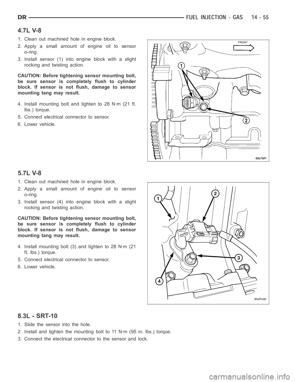
4.7L V-8
1. Clean out machined hole in engine block.
2. Apply a small amount of engine oil to sensor
o-ring.
3. Install sensor (1) into engine block with a slight
rocking and twisting action.
CAUTION: Before tightening sensor mounting bolt,
be sure sensor is completely flush to cylinder
block. If sensor is not flush, damage to sensor
mounting tang may result.
4. Install mounting bolt and tighten to 28 Nꞏm (21 ft.
lbs.) torque.
5. Connect electrical connector to sensor.
6. Lower vehicle.
5.7L V-8
1. Clean out machined hole in engine block.
2. Apply a small amount of engine oil to sensor
o-ring.
3. Install sensor (4) into engine block with a slight
rocking and twisting action.
CAUTION: Before tightening sensor mounting bolt,
be sure sensor is completely flush to cylinder
block. If sensor is not flush, damage to sensor
mounting tang may result.
4. Install mounting bolt (3) and tighten to 28 Nꞏm (21
ft. lbs.) torque.
5. Connect electrical connector to sensor.
6. Lower vehicle.
8.3L - SRT-10
1. Slide the sensor into the hole.
2. Install and tighten the mounting bolt to 11 Nꞏm (95 in. lbs.) torque.
3. Connect the electrical connector to the sensor and lock.
Page 2297 of 5267

12. Remove the fuel injector from the fuel rail.
INSTALLATION
3.7/ 4.7/ 5.7L
1. Install fuel injector(s) into fuel rail assembly and install retainingclip(s).
2. If same injector(s) is being reinstalled, install new O-ring(s).
3. Apply a small amount of clean engine oil to each injector O-ring. This will aid in installation.
4. Install fuel rail. (Refer to 14 - FUEL SYSTEM/FUEL DELIVERY/FUEL RAIL - INSTALLATION)
5. Start engine and check for fuel leaks.
8.3L - SRT-10
1. Install the fuel injectors to the fuel rail.
2. Install fuel rail under throttle body.
3. Apply a light coating of clean engine oiltotheO-ringonthenozzleendofeach injector.
4. Insert fuel injector nozzles into openings in intake manifold. Seat theinjectors in place. Tighten fuel rail bolts to
12 Nꞏm (105 in. lbs.).
5. Attach electrical connectors to fuel injectors.
6. Connect the electrical connector to the MAP sensor and Coolant Temperature sensor.
7. Connect the electrical connector to the TPS and Idle Air Control.
8. Install the wiring harness to the wiring clips under the throttle body.
9. Connect fuel supply tube to fuel rail. Refer to Quick Connect Fittings inthe Fuel Delivery section
10. Install the negative battery cable and install the battery cover.
11. Install the air cleaner assembly, refer to the Engine/Air Intake System/Air Cleaner Housing for more information.
12. Use the DRBIII
scan tool ASD Fuel System Test to pressurize the fuel system. Check for leaks.
Page 2300 of 5267

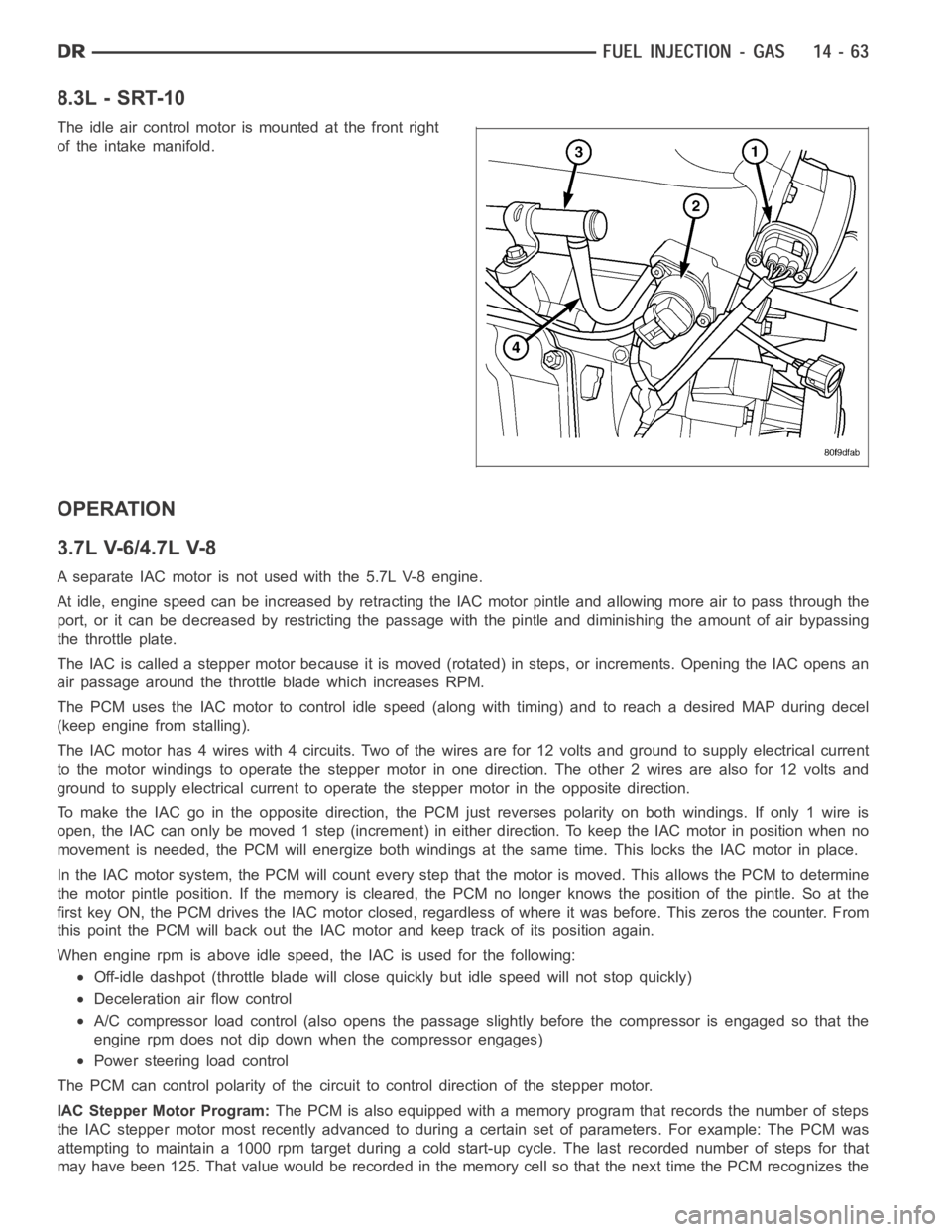
8.3L - SRT-10
The idle air control motor is mounted at the front right
of the intake manifold.
OPERATION
3.7L V-6/4.7L V-8
A separate IAC motor is not used with the 5.7L V-8 engine.
At idle, engine speed can be increased by retracting the IAC motor pintle and allowing more air to pass through the
port, or it can be decreased by restricting the passage with the pintle and diminishing the amount of air bypassing
the throttle plate.
The IAC is called a stepper motor because it is moved (rotated) in steps, or increments. Opening the IAC opens an
air passage around the throttle blade which increases RPM.
The PCM uses the IAC motor to control idle speed (along with timing) and to reach a desired MAP during decel
(keep engine from stalling).
The IAC motor has 4 wires with 4 circuits. Two of the wires are for 12 volts andground to supply electrical current
to the motor windings to operate the stepper motor in one direction. The other2wiresarealsofor12voltsand
ground to supply electrical current to operate the stepper motor in the opposite direction.
To make the IAC go in the opposite direction, the PCM just reverses polarityon both windings. If only 1 wire is
open, the IAC can only be moved 1 step (increment) in either direction. To keeptheIACmotorinpositionwhenno
movement is needed, the PCM will energize both windings at the same time. This locks the IAC motor in place.
In the IAC motor system, the PCM will count every step that the motor is moved. This allows the PCM to determine
the motor pintle position. If the memory is cleared, the PCM no longer knowsthe position of the pintle. So at the
first key ON, the PCM drives the IAC motor closed, regardless of where it wasbefore. This zeros the counter. From
this point the PCM will back out the IAC motor and keep track of its position again.
When engine rpm is above idle speed, the IAC is used for the following:
Off-idle dashpot (throttle blade will close quickly but idle speed will notstopquickly)
Deceleration air flow control
A/C compressor load control (also opens the passage slightly before the compressor is engaged so that the
engine rpm does not dip down when the compressor engages)
Power steering load control
The PCM can control polarity of the circuit to control direction of the stepper motor.
IAC Stepper Motor Program:The PCM is also equipped with a memory program that records the number of steps
the IAC stepper motor most recently advanced to during a certain set of parameters. For example: The PCM was
attempting to maintain a 1000 rpm target during a cold start-up cycle. The last recorded number of steps for that
may have been 125. That value would be recorded in the memory cell so that thenext time the PCM recognizes the
Page 2338 of 5267
INSTALLATION
3.7L V-6
The Throttle Position Sensor (TPS) (1) is mounted to
the throttle body.
The throttle shaft end of throttle body slides into a
socket in TPS. The TPS must be installed so that it
can be rotated a few degrees. (If sensor will not
rotate, install sensor with throttle shaft on other side of
socket tangs). The TPS will be under slight tension
when rotated.
1. Install TPS and retaining screws.
2. Tighten screws to 7 Nꞏm (60 in. lbs.) torque.
3. Connect TPS electrical connector to TPS.
4. Manually operate throttle (by hand) to check for
any TPS binding before starting engine.
5. Install air cleaner tube to throttle body.
Page 2339 of 5267
4.7L V-8
The throttle shaft end of throttle body (5) slides into a
socket in TPS. The TPS must be installed so that it
can be rotated a few degrees. If sensor will not rotate,
install sensor with throttle shaft on other side of socket
tangs. The TPS will be under slight tension when
rotated.
1. Install TPS and two retaining bolts.
2. Tighten bolts to 7 Nꞏm (60 in. lbs.) torque.
3. Manually operate throttle control lever by hand to
check for any binding of TPS.
4. Connect TPS electrical connector to TPS.
5. Install air duct/air box to throttle body.
Page 2340 of 5267
8.3L - SRT-10
The TPS is attached to the throttle body.
The throttle shaft end of the throttle body slides into a
socket in the TPS. When indexed correctly, the TPS
can rotate a few degrees to line up the mounting
screw holes with the screw holes in the throttle body.
If the sensor will not rotate into place, install the sen-
sor with the throttle shaft on the other side of the
socket tangs. The TPS has slight tension when rotated
to align the mounting holes.
1. Install TPS and mounting screws.
2. Attach electrical connector to the TPS.
Page 2351 of 5267

a. Install new o-ring seal to WIF sensor.
b. Apply a light film of clean oil to o-ring seal.
c. Install sensor into housing.
d. Tighten sensor to 2.5 Nꞏm (25 in. lbs.) torque.
e. Connect electrical connector to WIF sensor.
4.Fuel Heater Element:
a. Install fuel heater into fuel filter housing.
b. Install fuel heater thermostat onto the outside of the fuel filter housing.
c. Install fuel heater mounting screws and tighten to 1-1.5 Nꞏm (8 - 13 in. lbs.) torque.
d. Connect electrical connector to fuel heater thermostat.
e. Install new filter cover O-ring onto fuel filter housing cover and lubricate with clean engine oil.
f. Tighten fuel filter housing cover (lid) to 34 Nꞏm (25 ft. lbs.).
5.Drain Valve:
a. Install 2 new O-rings to valve.
b. Lubricate with silicon grease.
c. Installfueldrainvalve.
d. Install 4 mounting screws and tighten to 1–1.5 Nꞏm (8–13 in. lbs.) torque.
e. Connect drain hose to drain valve.
6. Install two new sealing washers to bolt.
7. Install screened banjo bolt Tighten to 24 Nꞏm (18 ft. lbs.)
8. Start engine and check for leaks.
Page 2358 of 5267

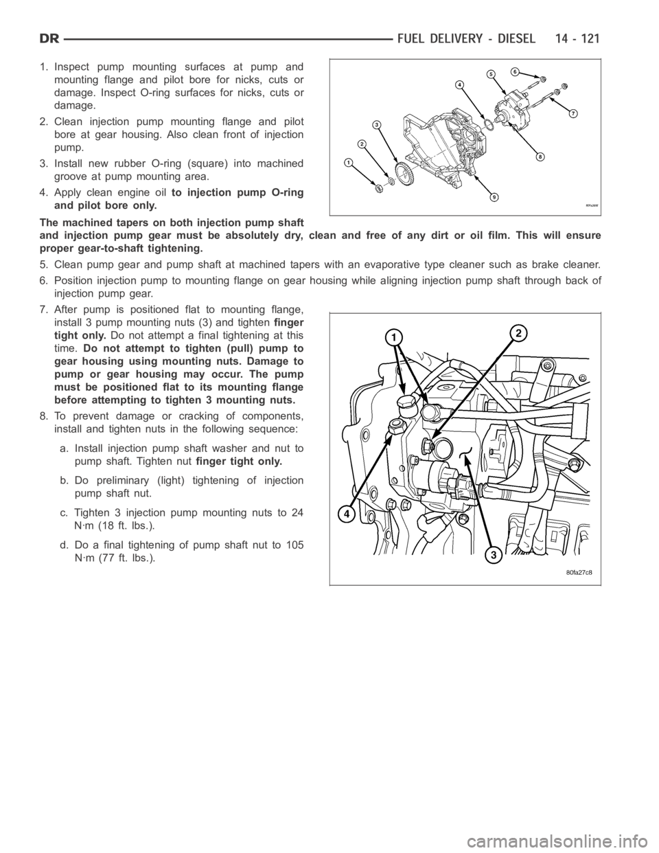
1. Inspect pump mounting surfaces at pump and
mounting flange and pilot bore for nicks, cuts or
damage. Inspect O-ring surfaces for nicks, cuts or
damage.
2. Clean injection pump mounting flange and pilot
bore at gear housing. Also clean front of injection
pump.
3. Install new rubber O-ring (square) into machined
groove at pump mounting area.
4. Apply clean engine oilto injection pump O-ring
and pilot bore only.
The machined tapers on both injection pump shaft
and injection pump gear must be absolutely dry, clean and free of any dirt oroil film. This will ensure
proper gear-to-shaft tightening.
5. Clean pump gear and pump shaft at machined tapers with an evaporative type cleaner such as brake cleaner.
6. Position injection pump to mounting flange on gear housing while aligning injection pump shaft through back of
injection pump gear.
7. After pump is positioned flat to mounting flange,
install 3 pump mounting nuts (3) and tightenfinger
tight only.Do not attempt a final tightening at this
time.Do not attempt to tighten (pull) pump to
gear housing using mounting nuts. Damage to
pump or gear housing may occur. The pump
must be positioned flat to its mounting flange
before attempting to tighten 3 mounting nuts.
8. To prevent damage or cracking of components,
install and tighten nuts in the following sequence:
a. Install injection pump shaft washer and nut to
pump shaft. Tighten nutfinger tight only.
b. Do preliminary (light) tightening of injection
pump shaft nut.
c. Tighten 3 injection pump mounting nuts to 24
Nꞏm (18 ft. lbs.).
d. Do a final tightening of pump shaft nut to 105
Nꞏm (77 ft. lbs.).