Page 2229 of 5267
INSTALLATION
1. OnLight Duty Vehicles, install the crossmember
(2) and the bolts (4). Tighten the bolts to 102 Nꞏm
(75 ft. lbs.).
2. Install the transmission mount nuts and tighten to
54 Nꞏm (40 ft. lbs.).
3. OnHeavy Duty Vehicles, install the crossmember
(4) and the bolts (3). Tighten the bolts to 115 Nꞏm
(85 ft. lbs.).
4. Install the transmission mount nuts and tighten to
54 Nꞏm (40 ft. lbs.).
5. Remove the transmission support (2).
Page 2231 of 5267
TRAILER HITCH
REMOVAL
1. Remove the rear bumper (Refer to 13 -FRAME & BUMPERS/BUMPERS/REAR BUMPER-REMOVAL).
2. OnLight Duty Vehicles, remove the hitch bolts (7)
Page 2233 of 5267
INSTALLATION
1. OnLight Duty Vehicles, install the hitch (5) onto the frame rails and make sure the locators (1 and2) on the
inside of the hitch brackets are engaged with the holes in the top of the frame rails properly.
2. Install the hitch bolts (7) and tighten to 170 Nꞏm (125 ft. lbs.).
3. Connect all wire harness support push pins.
Page 2257 of 5267

MODULE - FUEL PUMP
DESCRIPTION
The fuel pump module assembly is located on the top of the fuel tank. The complete assembly contains the fol-
lowing components:
A combination fuel filter/fuel pressure regulator
A separate fuel pick-up, or inlet filter
An electric fuel pump
Alockringtoretainpumpmoduletotank
A soft gasket between tank flange and module
A fuel gauge sending unit (fuel level sensor)
Fuel line connection
The fuel gauge sending unit may be serviced separately. If the electrical fuel pump, primary inlet filter, fuel filter or
fuel pressure regulator require service, the fuel pump module must be replaced.
OPERATION
Refer to Fuel Pump, Inlet Filter, Fuel Filter / Fuel Pressure Regulator andFuel Gauge Sending Unit.
REMOVAL
WARNING: The fuel system may be under a constant pressure (even with the engine off). Before servicing
the fuel pump module, the fuel system pressure must be released.
1. Drain and remove fuel tank. Refer to Fuel Tank
Removal/Installation.
2. Note rotational position of module before attempt-
ing removal. An indexing arrow is located on top of
module for this purpose.
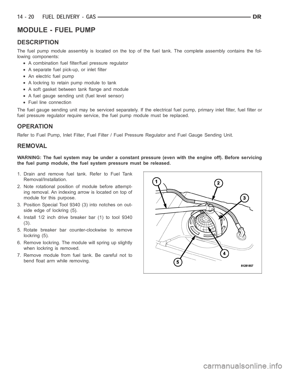
3. Position Special Tool 9340 (3) into notches on out-
side edge of lockring (5).
4. Install 1/2 inch drive breaker bar (1) to tool 9340
(3).
5. Rotate breaker bar counter-clockwise to remove
lockring (5).
6. Remove lockring. The module will spring up slightly
when lockring is removed.
7. Remove module from fuel tank. Be careful not to
bend float arm while removing.
Page 2267 of 5267

INSTALLATION
3.7L
1. If fuel injectors are to be installed, (Refer to 14 -
FUEL SYSTEM/FUEL INJECTION/FUEL INJEC-
TOR - INSTALLATION).
2. Clean out fuel injector machined bores in intake
manifold.
3. Apply a small amount of engine oil to each fuel
injector O-ring. This will helpin fuel rail installation.
4. Position fuel rail/fuel injector assembly to machined
injector openings in cylinder head.
5. Guide each injector into cylinder head. Be careful
not to tear injector O-rings.
6. Pushrightside of fuel rail down until fuel injectors
have bottomed on cylinder head shoulder. Push
leftfuel rail down until injectors have bottomed on
cylinder head shoulder.
7. Install 4 fuel rail mounting bolts and tighten. (Refer
to 14 - FUEL SYSTEM/FUEL DELIVERY - SPECI-
FICATIONS)
8. Install 6 ignition coils. (Refer to 8 - ELECTRICAL/
IGNITION CONTROL/IGNITION COIL - INSTALLA-
TION)
9. Connect electrical connectors to throttle body.
10. Connect electrical connectors at all fuel injectors.
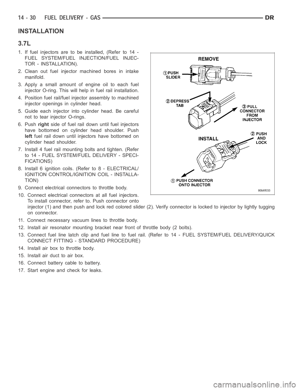
To install connector, refer to. Push connector onto
injector (1) and then push and lock red colored slider (2). Verify connector is locked to injector by lightly tugging
on connector.
11. Connect necessary vacuum lines to throttle body.
12. Install air resonator mounting bracket near front of throttle body (2 bolts).
13. Connect fuel line latch clip and fuel line to fuel rail. (Refer to 14 - FUEL SYSTEM/FUEL DELIVERY/QUICK
CONNECT FITTING - STANDARD PROCEDURE)
14. Install air box to throttle body.
15. Install air duct to air box.
16. Connect battery cable to battery.
17. Start engine and check for leaks.
Page 2268 of 5267

4.7L
1. If fuel injectors are to be installed, (Refer to 14 -
FUEL SYSTEM/FUEL INJECTION/FUEL INJEC-
TOR - INSTALLATION).
2. Clean out fuel injector machined bores in intake
manifold.
3. Apply a small amount of engine oil to each fuel
injector O-ring. This will helpin fuel rail installation.
4. Position fuel rail/fuel injector assembly to machined
injector openings in cylinder head.
5. Guide each injector into cylinder head. Be careful
not to tear injector O-rings.
6. Pushrightside of fuel rail down until fuel injectors
have bottomed on cylinder head shoulder. Push
leftfuel rail down until injectors have bottomed on
cylinder head shoulder.
7. Install 4 fuel rail mounting bolts and tighten. (Refer
to 14 - FUEL SYSTEM/FUEL DELIVERY - SPECI-
FICATIONS)
8. Install 8 ignition coils. (Refer to 8 - ELECTRICAL/
IGNITION CONTROL/IGNITION COIL - INSTALLA-
TION)
9. Connect electrical connectors to throttle body.
10. Connect electrical connectors at all fuel injectors.
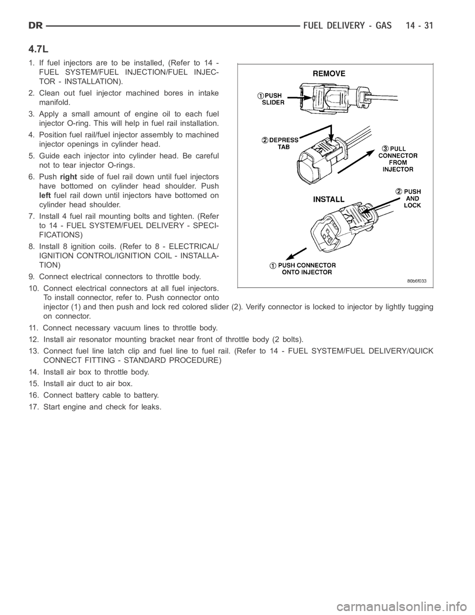
To install connector, refer to. Push connector onto
injector (1) and then push and lock red colored slider (2). Verify connector is locked to injector by lightly tugging
on connector.
11. Connect necessary vacuum lines to throttle body.
12. Install air resonator mounting bracket near front of throttle body (2 bolts).
13. Connect fuel line latch clip and fuel line to fuel rail. (Refer to 14 - FUEL SYSTEM/FUEL DELIVERY/QUICK
CONNECT FITTING - STANDARD PROCEDURE)
14. Install air box to throttle body.
15. Install air duct to air box.
16. Connect battery cable to battery.
17. Start engine and check for leaks.
Page 2269 of 5267

5.7L
1. If fuel injectors are to be installed, (Refer to 14 -
FUEL SYSTEM/FUEL INJECTION/FUEL INJEC-
TOR - INSTALLATION).
2. Clean out fuel injector machined bores in intake
manifold.
3. Apply a small amount of engine oil to each fuel
injector O-ring. This will helpin fuel rail installation.
4. Position fuel rail/fuel injector assembly to machined
injector openings in intake manifold.
5. Guide each injector into intake manifold. Be careful
not to tear injector O-rings.
6. Pushrightside of fuel rail down until fuel injectors
have bottomed on shoulders. Pushleftfuel rail
down until injectors have bottomed on shoulders.
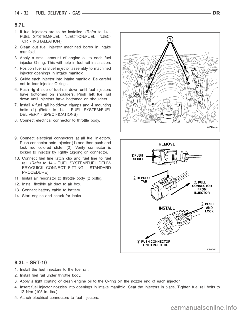
7. Install 4 fuel rail holddown clamps and 4 mounting
bolts (1) (Refer to 14 - FUEL SYSTEM/FUEL
DELIVERY - SPECIFICATIONS).
8. Connect electrical connector to throttle body.
9. Connect electrical connectors at all fuel injectors.
Push connector onto injector (1) and then push and
lock red colored slider (2). Verify connector is
locked to injector by lightly tugging on connector.
10. Connect fuel line latch clip and fuel line to fuel
rail. (Refer to 14 - FUEL SYSTEM/FUEL DELIV-
ERY/QUICK CONNECT FITTING - STANDARD
PROCEDURE).
11. Install air resonator to throttle body (2 bolts).
12. Install flexible air duct to air box.
13. Connect battery cable to battery.
14. Start engine and check for leaks.
8.3L - SRT-10
1. Install the fuel injectors to the fuel rail.
2. Install fuel rail under throttle body.
3. Apply a light coating of clean engine oiltotheO-ringonthenozzleendofeach injector.
4. Insert fuel injector nozzles into openings in intake manifold. Seat theinjectors in place. Tighten fuel rail bolts to
12 Nꞏm (105 in. lbs.).
5. Attach electrical connectors to fuel injectors.
Page 2291 of 5267
1. Disconnect electrical connector from crankshaft
position sensor.
2. Remove sensor mounting bolt.
3. Pull sensor out. A light tap to top of sensor may
ease removal.
INSTALLATION
3.7L V-6
1. Clean out machined hole in engine block.
2. Apply a small amount of engine oil to sensor O-ring
(3).
3. Install sensor into engine block with a slight rocking
and twisting action.
CAUTION: Before tightening sensor mounting bolt,
be sure sensor is completely flush to cylinder
block. If sensor is not flush, damage to sensor
mounting tang may result.
4. Install mounting bolt and tighten to 28 Nꞏm (21 ft.
lbs.) torque.
5. Connect electrical connector to sensor.
6. Lower vehicle.