2006 DODGE RAM SRT-10 light
[x] Cancel search: lightPage 2030 of 5267
3. Using a black light, inspect the entire engine for fluorescent dye, particularly at the suspected area of oil leak. If
the oil leak is found and identified, repair as necessary.
4. If dye is not observed, drive the vehicle at various speeds for approximately 24 km (15 miles), and repeat inspec-
tion.
5.If the oil leak source is not positively identified at this time, proceed with the air leak detection test method
as follows:
1. Disconnect the PCV hoses at the cylinder head covers and plug or cap the outlet on the covers.
2. Attach an air hose with pressure gauge and regulator to the dipstick tube.
CAUTION: Do not subject the engine assembly to more than 20.6 kpa (3 PSI) of test pressure.
3. Gradually apply air pressure from 6.89 kPa (1 psi) to 17.23 kPa (2.5 psi) maximum while applying soapy water
at the suspected source. Adjust the regulator to the suitable test pressure that provides the best bubbles which
will pinpoint the leak source. If the oil leak is detected and identified, repair per service manual procedures.
4. If the leakage occurs at the crankshaft rear oil seal area, refer to the section, Inspection for Rear Seal Area
Leak.
6. If no leaks are detected, turn off the air supply. Remove the air hose, allplugs, and caps. Connect the PCV
hoses. Proceed to next step.
7. Clean the oil off the suspect oil leak area using a suitable solvent. Drive the vehicle at various speeds approx-
imately 24 km (15 miles). Inspect the engine for signs of an oil leak by usinga black light.
NOTE: If oil leakage is observed at the dipstick tube to oil pan location; remove the tube, clean and reseal
using Mopar
Stud & Bearing Mount (press fit tube applications only), and for O-ring style tubes, remove
tube and replace the O-ring seal.
INSPECTION FOR REAR SEAL AREA LEAKS
Since it is sometimes difficult to determine the source of an oil leak in therear seal area of the engine, a more
involved inspection is necessary. The following steps should be followedto help pinpoint the source of the leak.
If the leakage occurs at the crankshaft rear oil seal area:
1. Disconnect the battery.
2. Raise the vehicle.
3. Remove clutch housing inspection cover and inspect rear of block for evidence of oil. Use a black light to check
for the oil leak. If a leak is present in this area, remove transmission for further inspection.
a. Circular spray pattern generally indicates seal leakage or crankshaftdamage.
b. Where leakage tends to run straight down, possible causes are a porous block, oil gallery cup plug or rear
crankshaft seal retainer gasket leak. See proper repair procedures for these items.
4. If no leaks are detected, pressurize the crankcase as previously described.
CAUTION: Do not exceed 20.6 kPa (3 psi).
5. If the leak is not detected, very slowly turn the crankshaft and watch forleakage. If a leak is detected between
the crankshaft and seal while slowly turning the crankshaft, it is possible the crankshaft seal surface is damaged.
The seal area on the crankshaft could have minor nicks or scratches that canbe polished out with emery cloth.
CAUTION: Use extreme caution when crankshaft polishing is necessary to remove minor nicks and
scratches. The crankshaft seal flange is especially machined to complement the function of the rear oil seal.
6. For bubbles that remain steady with shaft rotation, no further inspection can be done until disassembled.
7. After the oil leak root cause and appropriate corrective action have been identified, replace component(s) as
necessary.
Page 2031 of 5267
STANDARD PROCEDURE
ENGINE CORE AND OIL GALLERY PLUGS
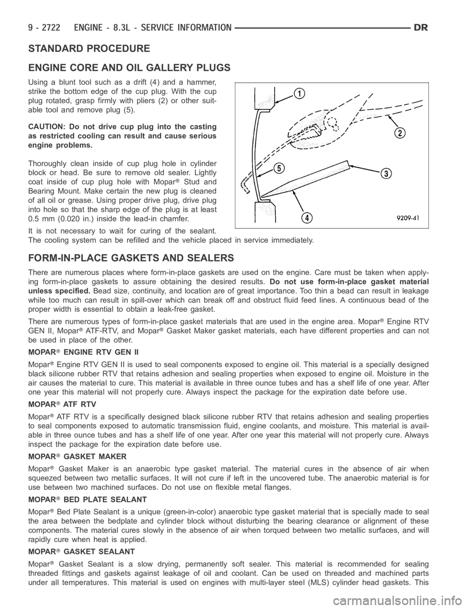
Using a blunt tool such as a drift (4) and a hammer,
strike the bottom edge of the cup plug. With the cup
plug rotated, grasp firmly with pliers (2) or other suit-
able tool and remove plug (5).
CAUTION: Do not drive cup plug into the casting
as restricted cooling can result and cause serious
engine problems.
Thoroughly clean inside of cup plug hole in cylinder
block or head. Be sure to remove old sealer. Lightly
coat inside of cup plug hole with Mopar
Stud and
Bearing Mount. Make certain the new plug is cleaned
of all oil or grease. Using proper drive plug, drive plug
into hole so that the sharp edge of the plug is at least
0.5 mm (0.020 in.) inside the lead-in chamfer.
It is not necessary to wait for curing of the sealant.
The cooling system can be refilled and the vehicle placed in service immediately.
FORM-IN-PLACE GASKETS AND SEALERS
There are numerous places where form-in-place gaskets are used on the engine. Care must be taken when apply-
ing form-in-place gaskets to assure obtaining the desired results.Do not use form-in-place gasket material
unless specified.Bead size, continuity, and location are of great importance. Too thin a bead can result in leakage
while too much can result in spill-overwhich can break off and obstruct fluid feed lines. A continuous bead of the
proper width is essential to obtain a leak-free gasket.
There are numerous types of form-in-place gasket materials that are used in the engine area. Mopar
Engine RTV
GEN II, Mopar
ATF-RTV, and MoparGasket Maker gasket materials, each have different properties and can not
be used in place of the other.
MOPAR
ENGINE RTV GEN II
Mopar
Engine RTV GEN II is used to seal components exposed to engine oil. This material is a specially designed
black silicone rubber RTV that retains adhesion and sealing properties when exposed to engine oil. Moisture in the
air causes the material to cure. This material is available in three ounce tubes and has a shelf life of one year. After
one year this material will not properly cure. Always inspect the package for the expiration date before use.
MOPAR
AT F R T V
Mopar
ATF RTV is a specifically designed black silicone rubber RTV that retains adhesion and sealing properties
to seal components exposed to automatic transmission fluid, engine coolants, and moisture. This material is avail-
able in three ounce tubes and has a shelf life of one year. After one year thismaterial will not properly cure. Always
inspect the package for the expiration date before use.
MOPAR
GASKET MAKER
Mopar
Gasket Maker is an anaerobic type gasket material. The material cures in the absence of air when
squeezed between two metallic surfaces. It will not cure if left in the uncovered tube. The anaerobic material is for
use between two machined surfaces. Do not use on flexible metal flanges.
MOPAR
BED PLATE SEALANT
Mopar
Bed Plate Sealant is a unique (green-in-color) anaerobic type gasket material that is specially made to seal
the area between the bedplate and cylinder block without disturbing the bearing clearance or alignment of these
components. The material cures slowly in the absence of air when torqued between two metallic surfaces, and will
rapidly cure when heat is applied.
MOPAR
GASKET SEALANT
Mopar
Gasket Sealant is a slow drying, permanently soft sealer. This material isrecommended for sealing
threaded fittings and gaskets against leakage of oil and coolant. Can be used on threaded and machined parts
under all temperatures. This material is used on engines with multi-layersteel (MLS) cylinder head gaskets. This
Page 2067 of 5267
CLEANING
CLEANING AND INSPECTION
1. Before cleaning, check for leaks, damage and
cracks.
2. Clean cylinder head and oil passages.
3. Check cylinder head for flatness.
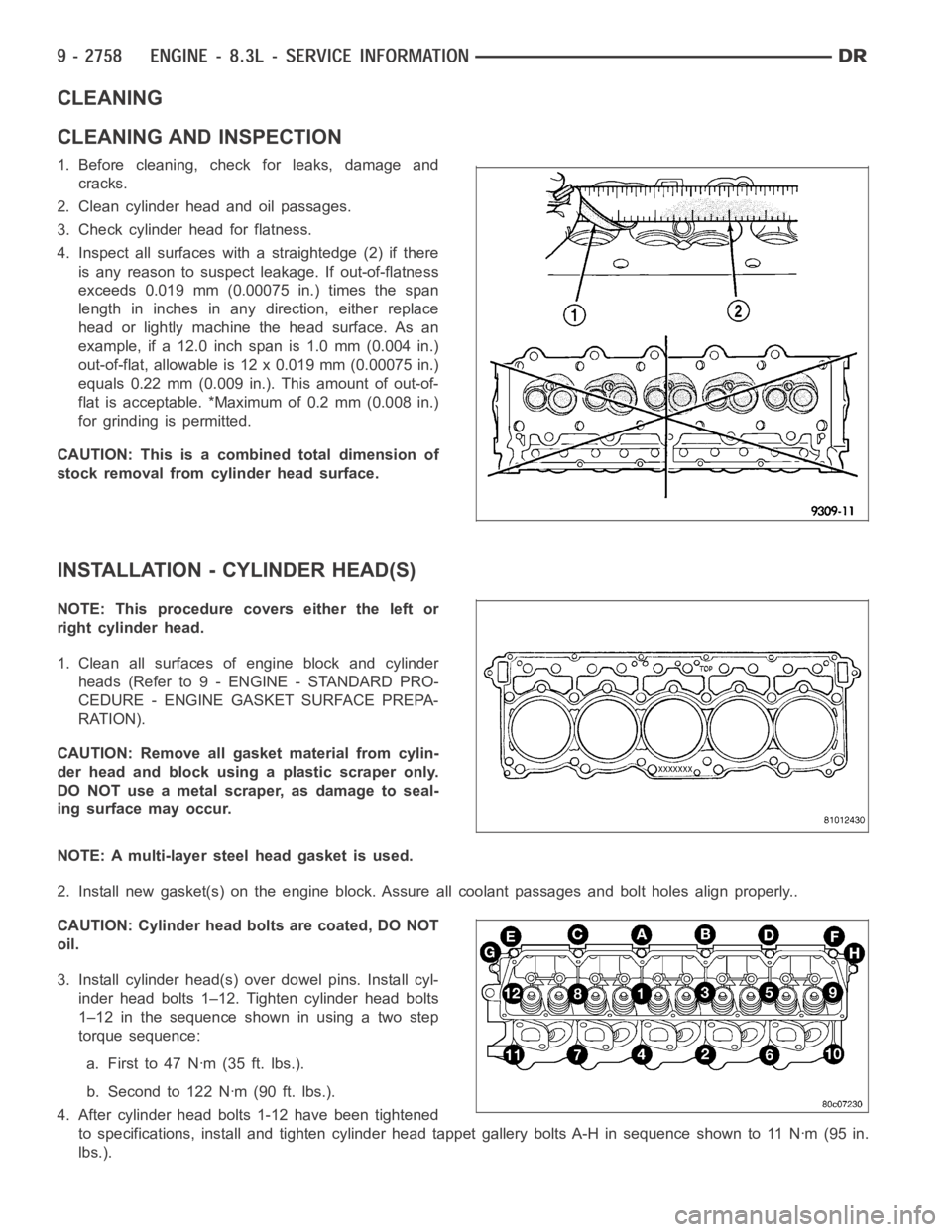
4. Inspect all surfaces with a straightedge (2) if there
is any reason to suspect leakage. If out-of-flatness
exceeds 0.019 mm (0.00075 in.) times the span
length in inches in any direction, either replace
head or lightly machine the head surface. As an
example, if a 12.0 inch span is 1.0 mm (0.004 in.)
out-of-flat, allowable is 12 x 0.019 mm (0.00075 in.)
equals 0.22 mm (0.009 in.). This amount of out-of-
flat is acceptable. *Maximum of 0.2 mm (0.008 in.)
for grinding is permitted.
CAUTION: This is a combined total dimension of
stock removal from cylinder head surface.
INSTALLATION - CYLINDER HEAD(S)
NOTE: This procedure covers either the left or
right cylinder head.
1. Clean all surfaces of engine block and cylinder
heads (Refer to 9 - ENGINE - STANDARD PRO-
CEDURE - ENGINE GASKET SURFACE PREPA-
RATION).
CAUTION: Remove all gasket material from cylin-
der head and block using a plastic scraper only.
DO NOT use a metal scraper, as damage to seal-
ing surface may occur.
NOTE: A multi-layer steel head gasket is used.
2. Install new gasket(s) on the engine block. Assure all coolant passages and bolt holes align properly..
CAUTION: Cylinder head bolts are coated, DO NOT
oil.
3. Install cylinder head(s) over dowel pins. Install cyl-
inder head bolts 1–12. Tighten cylinder head bolts
1–12 in the sequence shown in using a two step
torque sequence:
a. Firstto47Nꞏm(35ft.lbs.).
b. Second to 122 Nꞏm (90 ft. lbs.).
4. After cylinder head bolts 1-12 have been tightened
to specifications, install and tighten cylinder head tappet gallery bolts A-H in sequence shown to 11 Nꞏm (95 in.
lbs.).
Page 2075 of 5267
INTAKE/EXHAUST - VALVES/SEATS/GUIDES
STANDARD PROCEDURE - VALVE AND VALVE SEAT - REFACING
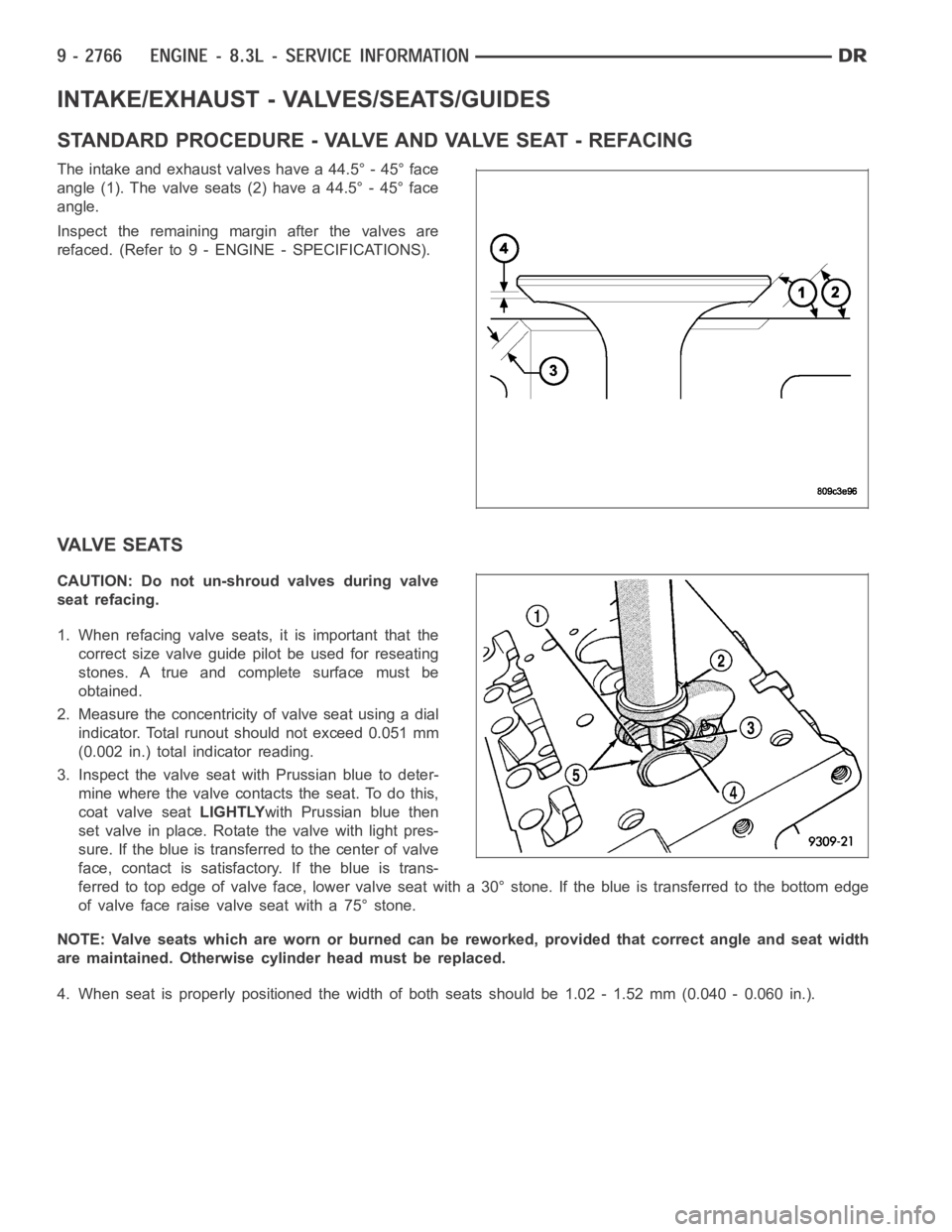
The intake and exhaust valves have a 44.5° - 45° face
angle (1). The valve seats (2) have a 44.5° - 45° face
angle.
Inspect the remaining margin after the valves are
refaced. (Refer to 9 - ENGINE - SPECIFICATIONS).
VALVE SEATS
CAUTION: Do not un-shroud valves during valve
seat refacing.
1. When refacing valve seats, it is important that the
correct size valve guide pilot be used for reseating
stones. A true and complete surface must be
obtained.
2. Measure the concentricity of valve seat using a dial
indicator. Total runout should not exceed 0.051 mm
(0.002 in.) total indicator reading.
3. Inspect the valve seat with Prussian blue to deter-
mine where the valve contacts the seat. To do this,
coat valve seatLIGHTLYwith Prussian blue then
set valve in place. Rotate the valve with light pres-
sure. If the blue is transferred to the center of valve
face, contact is satisfactory. If the blue is trans-
ferred to top edge of valve face, lower valve seat with a 30° stone. If the blue is transferred to the bottom edge
of valve face raise valve seat with a 75° stone.
NOTE: Valve seats which are worn or burned can be reworked, provided that correct angle and seat width
are maintained. Otherwise cylinder head must be replaced.
4. When seat is properly positioned the width of both seats should be 1.02 - 1.52 mm (0.040 - 0.060 in.).
Page 2086 of 5267
LUBRICATION
DESCRIPTION
The engine lubrication system is a full-flow filtration pressure feed type.
OPERATION
Engine oil stored in the oil pan is taken in and discharged by an internal geartypeoilpump,whichisdrivenbythe
crankshaft. A pressure relief valve is located in the timing chain case cover; it regulates oil pressure. The oil is
pumped through an oil filter and feeds a main oil gallery. Also, oil is routedtoanexternaloilcooler.Themainoil
gallery feeds oil under pressure to the main bearings, connecting rod bearings, and camshaft bearings. Passages in
the cylinder block feed oil to the hydraulic lifters. The oil then flows through hollow pushrods, which feed the rocker
arm pivots.
DIAGNOSIS AND TESTING
CHECKING ENGINE OIL PRESSURE
1. Remove oil pressure sensor (Refer to 9 - ENGINE/LUBRICATION/OIL PRESSURE SENSOR - REMOVAL).
2. Install oil pressure gauge.
3. Warm engine at high idle until thermostat opens.
CAUTION: If oil pressure is 0 at idle, Do Not Run engine at 3000 RPM.
4. Oil pressure should be 68.9 kPa (10 psi) at idle or 310 - 517 kPa (45 - 75 psi)at 3000 RPM.
5. If oil pressure is 0 at idle, shut off engine. Check for a clogged oil pick-up screen or a pressure relief valve stuck
open.
ENGINE OIL LEAK
Begin with a thorough visual inspection of the engine, particularly at thearea of the suspected leak. If an oil leak
source is not readily identifiable, thefollowingstepsshouldbefollowed:
1. Do not clean or degrease the engine at this time because some solvents maycause rubber to swell, temporarily
stopping the leak.
2. Add an oil soluble dye (use as recommended by manufacturer). Start the engine and let idle for approximately 15
minutes. Check the oil dipstick to make sure the dye is thoroughly mixed as indicated with a bright yellow color
under a black light.
3. Using a black light, inspect the entire engine for fluorescent dye, particularly at the suspected area of oil leak. If
the oil leak is found and identified, repair per service manual instructions.
4. If dye is not observed, drive the vehicle at various speeds for approximately 24 km (15 miles), and repeat inspec-
tion.If the oil leak source is not positively identified at this time, proceed with the air leak detection test
method.
Air Leak Detection Test Method
1. Remove the PCV valve from the IAFM. Cap or plug the PCV valve grommet.
2. Attach an air hose with pressure gauge and regulator to the dipstick tube.
CAUTION: Do not subject the engine assembly to more than 20.6 kPa (3 PSI) of test pressure.
3. Gradually apply air pressure from 6.89 - 17.23 kPa (1 - 2.5 psi) maximum while applying soapy water at the
suspected source. Adjust the regulator to the suitable test pressure thatprovide the best bubbles which will pin-
point the leak source. If the oil leak is detected and identified, repair per service manual procedures.
4. If the leakage occurs at the rear oil seal area, refer to the section, Inspection for Rear Seal Area Leak.
5. If no leaks are detected, turn off the air supply and remove the air hose and all plugs and caps. Install the PCV
valve.
6. Clean the oil off the suspect oil leak area using a suitable solvent. Drive the vehicle at various speeds approx-
imately 24 km (15 miles). Inspect the engine for signs of an oil leak by usinga black light.
Page 2087 of 5267
INSPECTION FOR REAR SEAL AREA LEAKS
Since it is sometimes difficult to determine the source of an oil leak in therear seal area of the engine, a more
involved inspection is necessary. The following steps should be followedto help pinpoint the source of the leak.
If the leakage occurs at the crankshaft rear oil seal area:
1. Disconnect the battery.
2. Raise the vehicle.
3. Remove torque converter or clutch housing cover and inspect rear of block for evidence of oil. Use a black light
to check for the oil leak:
a. Circular spray pattern generally indicates seal leakage or crankshaftdamage.
b. Where leakage tends to run straight down, possible causes are a porous block, distributor seal, camshaft
bore cup plugs oil galley pipe plugs, oil filter runoff, and main bearing cap to cylinder block mating surfaces.
4. If no leaks are detected, pressurize the crankcase as outlined in the, Inspection (Engine oil Leaks in general)
CAUTION: Do not exceed 20.6 kPa (3 psi).
5. If the leak is not detected, very slowly turn the crankshaft and watch forleakage. If a leak is detected between
the crankshaft and seal while slowly turning the crankshaft, it is possible the crankshaft seal surface is damaged.
The seal area on the crankshaft could have minor nicks or scratches that canbe polished out with emery cloth.
CAUTION: Use extreme caution when crankshaft polishing is necessary to remove minor nicks and
scratches. The crankshaft seal flange is especially machined to complement the function of the rear oil seal.
6. For bubbles that remain steady with shaft rotation, no further inspection can be done until disassembled.
Page 2104 of 5267
BLOCK-ENGINE
DESCRIPTION
The cylinder block is made of a sand-cast aluminum alloy. The cylinder block has interference-fit cast iron cylinder
liners. The cylinder liners are thermally installed during block manufacturing; they are not serviceable items.
Six iron main bearing caps use four bolts per cap; two vertical and two horizontal. A crankshaft oil scraper is
attached to the main bearing caps via extended main bearing cap bolts and nuts.
STANDARD PROCEDURE - CYLINDER BORE HONING
Before honing, stuff plenty of clean shop towels under
the bores and over the crankshaft to keep abrasive
materials from entering the crankshaft area.
1. Used carefully, the Cylinder Bore Sizing Hone
C-823, equipped with 220 grit stones, is the best
tool for this job. In addition to deglazing, it will
reduce taper and out-of-round, as well as removing
light scuffing, scoring and scratches. Usually, a few
strokes will clean up a bore and maintain the
required limits.
CAUTION: DO NOT use rigid type hones to remove
cylinder wall glaze.
2. Deglazing of the cylinder walls may be done if the
cylinder bore is straight and round. Use a cylinder
surfacing hone, Honing Tool C-3501, equipped with
280 grit stones (C-3501-3810). about 20-60
strokes, depending on the bore condition, will be
sufficient to provide a satisfactory surface. Using
honing oil C-3501-3880, or a light honing oil, avail-
able from major oil distributors.
CAUTION: DO NOT use engine or transmission oil, mineral spirits, or kerosene.
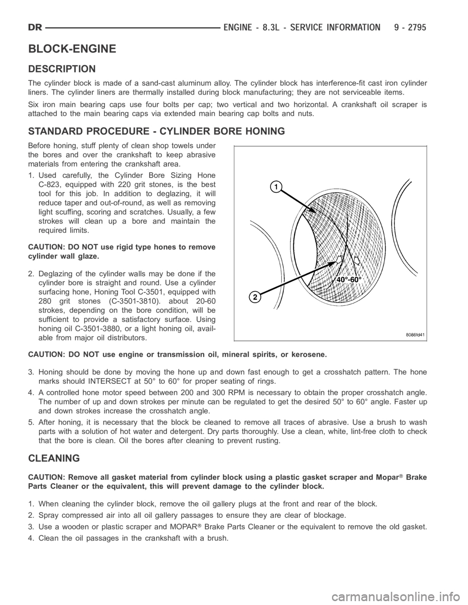
3. Honing should be done by moving the hone up and down fast enough to get a crosshatch pattern. The hone
marks should INTERSECT at 50° to 60° for proper seating of rings.
4. A controlled hone motor speed between 200 and 300 RPM is necessary to obtain the proper crosshatch angle.
The number of up and down strokes per minute can be regulated to get the desired 50° to 60° angle. Faster up
and down strokes increase the crosshatch angle.
5. After honing, it is necessary that the block be cleaned to remove all traces of abrasive. Use a brush to wash
parts with a solution of hot water and detergent. Dry parts thoroughly. Usea clean, white, lint-free cloth to check
that the bore is clean. Oil the bores after cleaning to prevent rusting.
CLEANING
CAUTION: Remove all gasket material from cylinder block using a plastic gasket scraper and MoparBrake
Parts Cleaner or the equivalent, this will prevent damage to the cylinder block.
1. When cleaning the cylinder block, remove the oil gallery plugs at the front and rear of the block.
2. Spray compressed air into all oil gallery passages to ensure they are clear of blockage.
3. Use a wooden or plastic scraper and MOPAR
Brake Parts Cleaner or the equivalent to remove the old gasket.
4. Clean the oil passages in the crankshaft with a brush.
Page 2137 of 5267
EXHAUST SYSTEM
DESCRIPTION
GAS ENGINES
CAUTION: Avoid application of rust prevention compounds or undercoatingmaterials to exhaust system
floor pan exhaust heat shields. Light overspray near the edges is permitted. Application of coating will
result in excessive floor pan temperatures and objectionable fumes.
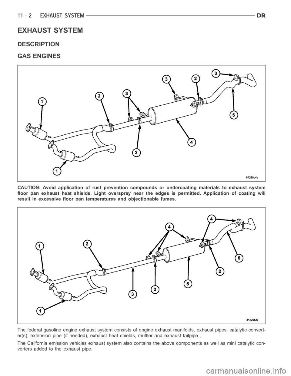
The federal gasoline engine exhaust system consists of engine exhaust manifolds, exhaust pipes, catalytic convert-
er(s), extension pipe (if needed), exhaust heat shields, muffler and exhaust tailpipe ,.
The California emission vehicles exhaust system also contains the above components as well as mini catalytic con-
verters added to the exhaust pipe.