2006 DODGE RAM SRT-10 light
[x] Cancel search: lightPage 1688 of 5267
ENGINE BLOCK
DESCRIPTION
The cylinder block is made of cast iron.The block is a closed deck design with the left bank forward. To provide
high rigidity and improved NVH an enhanced compacted graphite bedplate isbolted to the block. The block design
allows coolant flow between the cylinders bores, and an internal coolant bypass to a single poppet inlet thermostat
is included in the cast aluminum front cover.
STANDARD PROCEDURE - CYLINDER BORE HONING
Before honing, stuff plenty of clean shop towels under
the bores and over the crankshaft to keep abrasive
materials from entering the crankshaft area.
1. Used carefully, the Cylinder Bore Sizing Hone
C-823, equipped with 220 grit stones, is the best
tool for this job. In addition to deglazing, it will
reduce taper and out-of-round, as well as removing
light scuffing, scoring and scratches. Usually, a few
strokes will clean up a bore and maintain the
required limits.
CAUTION: DO NOT use rigid type hones to remove
cylinder wall glaze.
2. Deglazing of the cylinder walls may be done if the
cylinder bore is straight and round. Use a cylinder
surfacing hone, Honing Tool C-3501, equipped with
280 grit stones (C-3501-3810). about 20-60
strokes, depending on the bore condition, will be
sufficient to provide a satisfactory surface. Using
honing oil C-3501-3880, or a light honing oil, avail-
able from major oil distributors.
CAUTION: DO NOT use engine or transmission oil, mineral spirits, or kerosene.
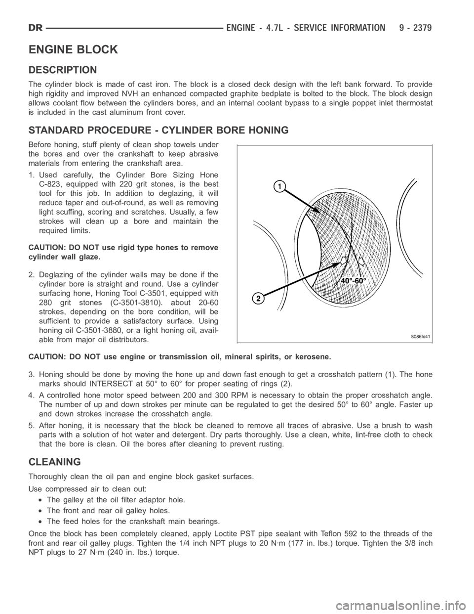
3. Honing should be done by moving the hone up and down fast enough to get a crosshatch pattern (1). The hone
marks should INTERSECT at 50° to 60° for proper seating of rings (2).
4. A controlled hone motor speed between 200 and 300 RPM is necessary to obtain the proper crosshatch angle.
The number of up and down strokes per minute can be regulated to get the desired 50° to 60° angle. Faster up
and down strokes increase the crosshatch angle.
5. After honing, it is necessary that the block be cleaned to remove all traces of abrasive. Use a brush to wash
parts with a solution of hot water and detergent. Dry parts thoroughly. Usea clean, white, lint-free cloth to check
that the bore is clean. Oil the bores after cleaning to prevent rusting.
CLEANING
Thoroughly clean the oil pan and engine block gasket surfaces.
Use compressed air to clean out:
The galley at the oil filter adaptor hole.
The front and rear oil galley holes.
The feed holes for the crankshaft main bearings.
Once the block has been completely cleaned, apply Loctite PST pipe sealantwith Teflon 592 to the threads of the
front and rear oil galley plugs. Tighten the 1/4 inch NPT plugs to 20 Nꞏm (177in. lbs.) torque. Tighten the 3/8 inch
NPT plugs to 27 Nꞏm (240 in. lbs.) torque.
Page 1689 of 5267
INSPECTION
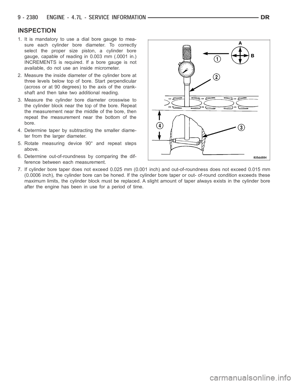
1. It is mandatory to use a dial bore gauge to mea-
sure each cylinder bore diameter. To correctly
select the proper size piston, a cylinder bore
gauge, capable of reading in 0.003 mm (.0001 in.)
INCREMENTS is required. If a bore gauge is not
available, do not use an inside micrometer.
2. Measure the inside diameter of the cylinder bore at
three levels below top of bore. Start perpendicular
(across or at 90 degrees) to the axis of the crank-
shaft and then take two additional reading.
3. Measure the cylinder bore diameter crosswise to
the cylinder block near the top of the bore. Repeat
the measurement near the middle of the bore, then
repeat the measurement near the bottom of the
bore.
4. Determine taper by subtracting the smaller diame-
ter from the larger diameter.
5. Rotate measuring device 90° and repeat steps
above.
6. Determine out-of-roundness by comparing the dif-
ference between each measurement.
7. If cylinder bore taper does not exceed 0.025 mm (0.001 inch) and out-of-roundness does not exceed 0.015 mm
(0.0006 inch), the cylinder bore can be honed. If the cylinder bore taper orout- of-round condition exceeds these
maximum limits, the cylinder block must be replaced. A slight amount of taper always exists in the cylinder bore
after the engine has been in use for a period of time.
Page 1702 of 5267
SEAL - CRANKSHAFT OIL - REAR
DIAGNOSIS AND TESTING - REAR SEAL AREA LEAKS
Since it is sometimes difficult to determine the source of an oil leak in therear seal area of the engine, a more
involved inspection is necessary. The following steps should be followedto help pinpoint the source of the leak.
If the leakage occurs at the crankshaft rear oil seal area:
1. Disconnect the battery.
2. Raise the vehicle.
3. Remove torque converter or clutch housing cover and inspect rear of block for evidence of oil. Use a black light
to check for the oil leak:
a. Circular spray pattern generally indicates seal leakage or crankshaftdamage.
b. Where leakage tends to run straight down, possible causes are a porous block, oil galley pipe plugs, oil filter
runoff, and main bearing cap to cylinder block mating surfaces. See Engine, for proper repair procedures of
these items.
4. If no leaks are detected, pressurized the crankcase as outlined in the section, Inspection (Engine oil Leaks in
general)
CAUTION: Do not exceed 20.6 kPa (3 psi).
5. If the leak is not detected, very slowly turn the crankshaft and watch forleakage. If a leak is detected between
the crankshaft and seal while slowly turning the crankshaft, it is possible the crankshaft seal surface is damaged.
The seal area on the crankshaft could have minor nicks or scratches that canbe polished out with emery cloth.
CAUTION: Use extreme caution when crankshaft polishing is necessary to remove minor nicks or
scratches. The crankshaft seal flange is specially machined to complement the function of the rear oil seal.
6. For bubbles that remain steady with shaft rotation, no further inspection can be done until disassembled. (Refer
to 9 - ENGINE - DIAGNOSIS AND TESTING), under the Oil Leak row, for components inspections on possible
causes and corrections.
7. After the oil leak root cause and appropriate corrective action have been identified, (Refer to 9 - ENGINE/EN-
GINE BLOCK/CRANKSHAFT OIL SEAL - REAR - REMOVAL).
REMOVAL
NOTE: This procedure can be performed in vehi-
cle.
1. If being performed in vehicle, remove the transmis-
sion.
2. Remove the flexplate (Refer to 9 - ENGINE/EN-
GINE BLOCK/FLEX PLATE - REMOVAL).
NOTE: The crankshaft oil seal CAN NOT be reused
after removal.
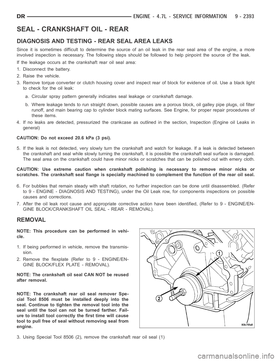
NOTE: The crankshaft rear oil seal remover Spe-
cial Tool 8506 must be installed deeply into the
seal. Continue to tighten the removal tool into the
seal until the tool can not be turned farther. Fail-
ure to install tool correctly the first time will cause
tool to pull free of seal without removing seal from
engine.
3. Using Special Tool 8506 (2), remove the crankshaft rear oil seal (1)
Page 1705 of 5267
ROD - PISTON & CONNECTING
DESCRIPTION
CAUTION: Do not use a metal stamp to mark connecting rods as damage may result, instead use ink or a
scratch awl.
Thepistonsaremadeofahighstrengthaluminumalloy.Theanodizedtopring groove and crown has been
replaced with a coated top ring that is blue in color on the bottom surface. Piston skirts are coated with a solid
lubricant (Molykote) to reduce friction and provide scuff resistance. The connecting rods are made of forged pow-
dered metal, with a “fractured cap” design. A pressed fit piston pin is usedto attach the piston and connecting rod.
STANDARD PROCEDURE - PISTON FITTING
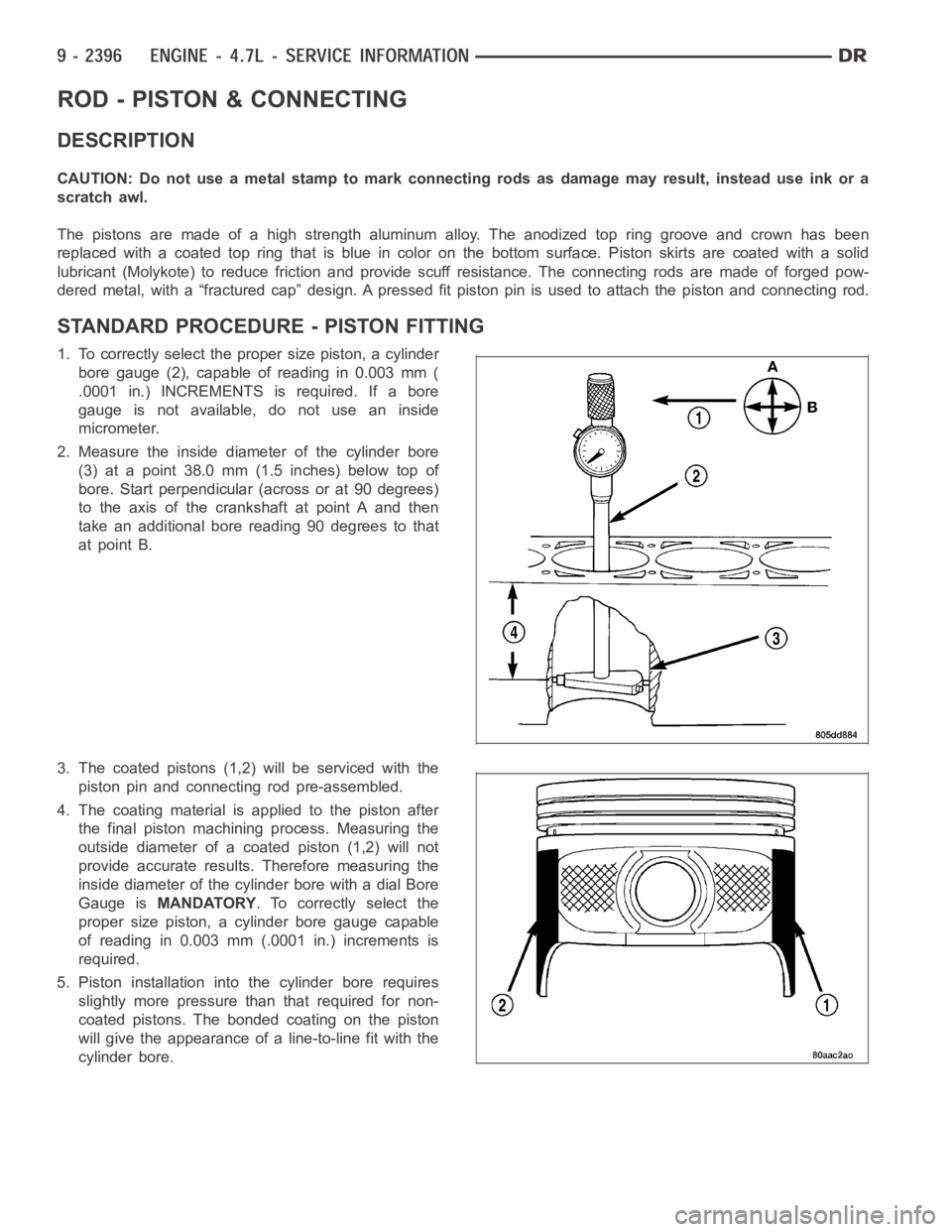
1. To correctly select the proper size piston, a cylinder
bore gauge (2), capable of reading in 0.003 mm (
.0001 in.) INCREMENTS is required. If a bore
gauge is not available, do not use an inside
micrometer.
2. Measure the inside diameter of the cylinder bore
(3) at a point 38.0 mm (1.5 inches) below top of
bore. Start perpendicular (across or at 90 degrees)
to the axis of the crankshaft at point A and then
take an additional bore reading 90 degrees to that
at point B.
3. The coated pistons (1,2) will be serviced with the
piston pin and connecting rod pre-assembled.
4. The coating material is applied to the piston after
the final piston machining process. Measuring the
outside diameter of a coated piston (1,2) will not
provide accurate results. Therefore measuring the
inside diameter of the cylinder bore with a dial Bore
Gauge isMANDATORY. To correctly select the
proper size piston, a cylinder bore gauge capable
of reading in 0.003 mm (.0001 in.) increments is
required.
5. Piston installation intothe cylinder bore requires
slightly more pressure than that required for non-
coated pistons. The bonded coating on the piston
will give the appearance of a line-to-line fit with the
cylinder bore.
Page 1713 of 5267
INSTALLATION
CAUTION: To prevent severe damage to the Crank-
shaft, Damper or Special Tool 8512–A, thoroughly
clean the damper bore and the crankshaft nose
before installing Damper.
1. Align crankshaft damper slot with key in crankshaft.
Slide damper onto crankshaft slightly.
CAUTION: Special Tool 8512–A, is assembled in a
specific sequence. Failure to assemble this tool in
this sequence can result in tool failure and severe
damage to either the tool or the crankshaft.
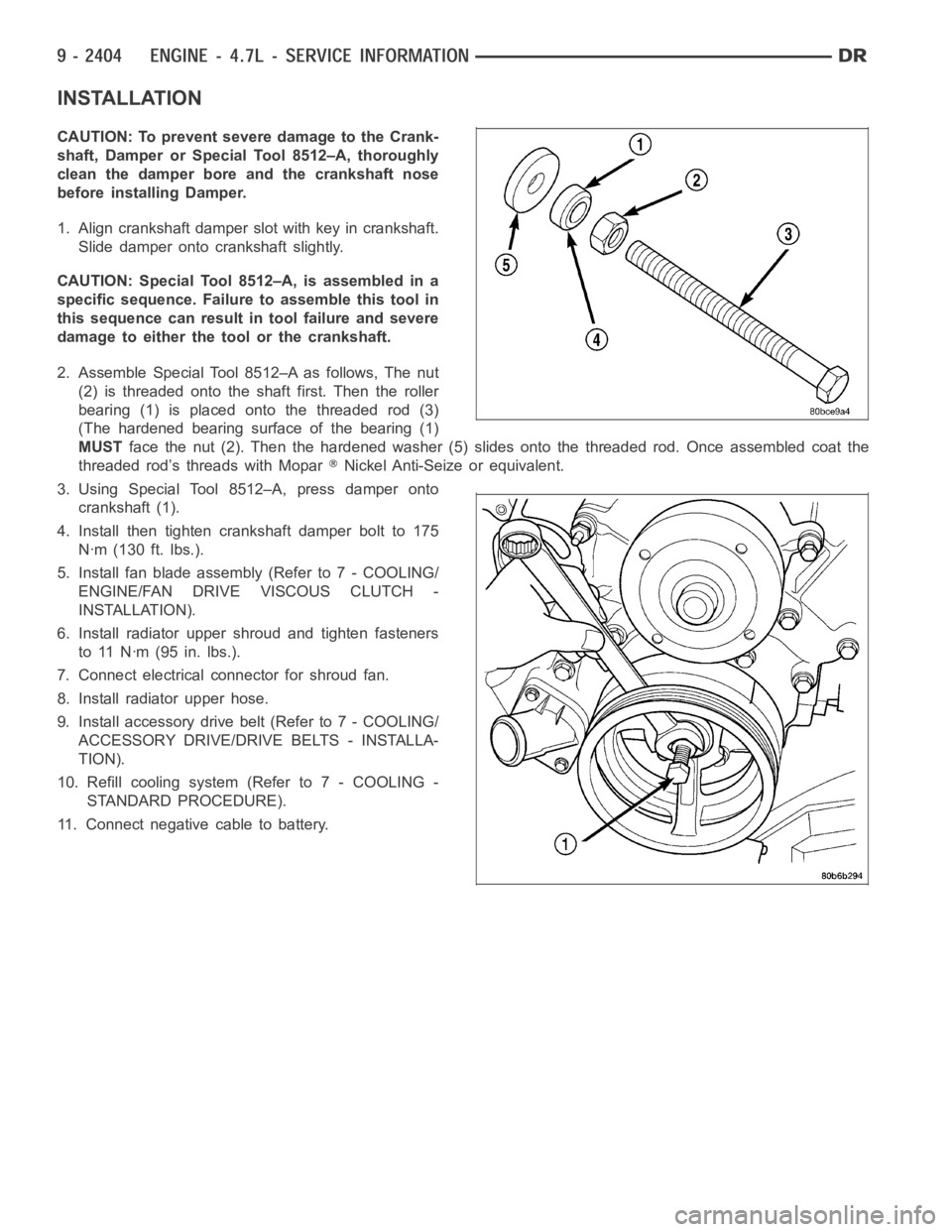
2. Assemble Special Tool 8512–A as follows, The nut
(2) is threaded onto the shaft first. Then the roller
bearing (1) is placed onto the threaded rod (3)
(The hardened bearing surface of the bearing (1)
MUSTface the nut (2). Then the hardened washer (5) slides onto the threaded rod.Once assembled coat the
threaded rod’s threads with Mopar
Nickel Anti-Seize or equivalent.
3. Using Special Tool 8512–A, press damper onto
crankshaft (1).
4. Install then tighten crankshaft damper bolt to 175
Nꞏm (130 ft. lbs.).
5. Install fan blade assembly (Refer to 7 - COOLING/
ENGINE/FAN DRIVE VISCOUS CLUTCH -
INSTALLATION).
6. Install radiator upper shroud and tighten fasteners
to 11 Nꞏm (95 in. lbs.).
7. Connect electrical connector for shroud fan.
8. Install radiator upper hose.
9. Install accessory drive belt (Refer to 7 - COOLING/
ACCESSORY DRIVE/DRIVE BELTS - INSTALLA-
TION).
10. Refill cooling system (Refer to 7 - COOLING -
STANDARD PROCEDURE).
11. Connect negative cable to battery.
Page 1722 of 5267
DIAGNOSIS AND TESTING - ENGINE OIL LEAK
Begin with a thorough visual inspection of the engine, particularly at thearea of the suspected leak. If an oil leak
source is not readily identifiable, thefollowingstepsshouldbefollowed:
1. Do not clean or degrease the engine at this time because some solvents maycause rubber to swell, temporarily
stopping the leak.
2. Add an oil soluble dye (use as recommended by manufacturer). Start the engine and let idle for approximately 15
minutes. Check the oil dipstick to make sure the dye is thoroughly mixed as indicated with a bright yellow color
under a black light.
3. Using a black light, inspect the entire engine for fluorescent dye, particularly at the suspected area of oil leak. If
the oil leak is found and identified, repair per service manual instructions.
4. If dye is not observed, drive the vehicle at various speeds for approximately 24 km (15 miles), and repeat inspec-
tion.If the oil leak source is not positively identified at this time, proceed with the air leak detection test method.
Air Leak Detection Test Method
1. Disconnect the breather cap to air cleaner hose at the breather cap end. Cap or plug breather cap nipple.
2. Remove the PCV valve from the cylinder head cover. Cap or plug the PCV valvegrommet.
3. Attach an air hose with pressure gauge and regulator to the dipstick tube.
CAUTION: Do not subject the engine assembly to more than 20.6 kPa (3 PSI) of test pressure.
4. Gradually apply air pressure from 1 psi to 2.5 psi maximum while applyingsoapy water at the suspected source.
Adjust the regulator to the suitable test pressure that provide the best bubbles which will pinpoint the leak
source. If the oil leak is detected and identified, repair per service manual procedures.
5. If the leakage occurs at the rear oil seal area, refer to the section, Inspection for Rear Seal Area Leak.
6. If no leaks are detected, turn off the air supply and remove the air hose and all plugs and caps. Install the PCV
valve and breather cap hose.
7. Clean the oil off the suspect oil leak area using a suitable solvent. Drive the vehicle at various speeds approx-
imately 24 km (15 miles). Inspect the engine for signs of an oil leak by usinga black light.
INSPECTION FOR REAR SEAL AREA LEAKS
Since it is sometimes difficult to determine the source of an oil leak in therear seal area of the engine, a more
involved inspection is necessary. The following steps should be followedto help pinpoint the source of the leak.
If the leakage occurs at the crankshaft rear oil seal area:
1. Disconnect the battery.
2. Raise the vehicle.
3. Remove torque converter or clutch housing cover and inspect rear of block for evidence of oil. Use a black light
to check for the oil leak:
a. Circular spray pattern generally indicates seal leakage or crankshaftdamage.
b. Where leakage tends to run straight down, possible causes are a porous block, oil galley pipe plugs, oil filter
runoff, and main bearing cap to cylinder block mating surfaces.
4. If no leaks are detected, pressurize the crankcase as outlined in the, Inspection (Engine oil Leaks in general)
CAUTION: Do not exceed 20.6 kPa (3 psi).
5. If the leak is not detected, very slowly turn the crankshaft and watch forleakage. If a leak is detected between
the crankshaft and seal while slowly turning the crankshaft, it is possible the crankshaft seal surface is damaged.
The seal area on the crankshaft could have minor nicks or scratches that canbe polished out with emery cloth.
CAUTION: Use extreme caution when crankshaft polishing is necessary to remove minor nicks and
scratches. The crankshaft seal flange is especially machined to complement the function of the rear oil seal.
6. For bubbles that remain steady with shaft rotation, no further inspection can be done until disassembled.
Page 1725 of 5267
FILTER - ENGINE OIL
REMOVAL
All engines are equipped with a high quality full-flow,
disposable type oil filter. DaimlerChrysler Corporation
recommends a Mopar
or equivalent oil filter be used.
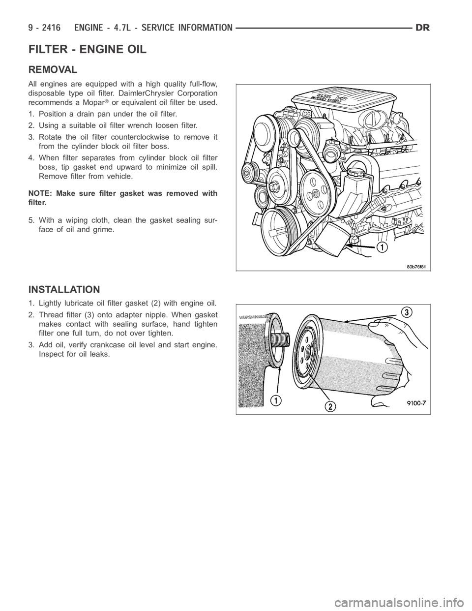
1. Position a drain pan under the oil filter.
2. Using a suitable oil filter wrench loosen filter.
3. Rotate the oil filter counterclockwise to remove it
from the cylinder block oil filter boss.
4. When filter separates from cylinder block oil filter
boss, tip gasket end upward to minimize oil spill.
Remove filter from vehicle.
NOTE: Make sure filter gasket was removed with
filter.
5. With a wiping cloth, clean the gasket sealing sur-
face of oil and grime.
INSTALLATION
1. Lightly lubricate oil filter gasket (2) with engine oil.
2. Thread filter (3) onto adapter nipple. When gasket
makes contact with sealing surface, hand tighten
filter one full turn, do not over tighten.
3. Add oil, verify crankcase oil level and start engine.
Inspect for oil leaks.
Page 1735 of 5267
MANIFOLD - EXHAUST
DESCRIPTION
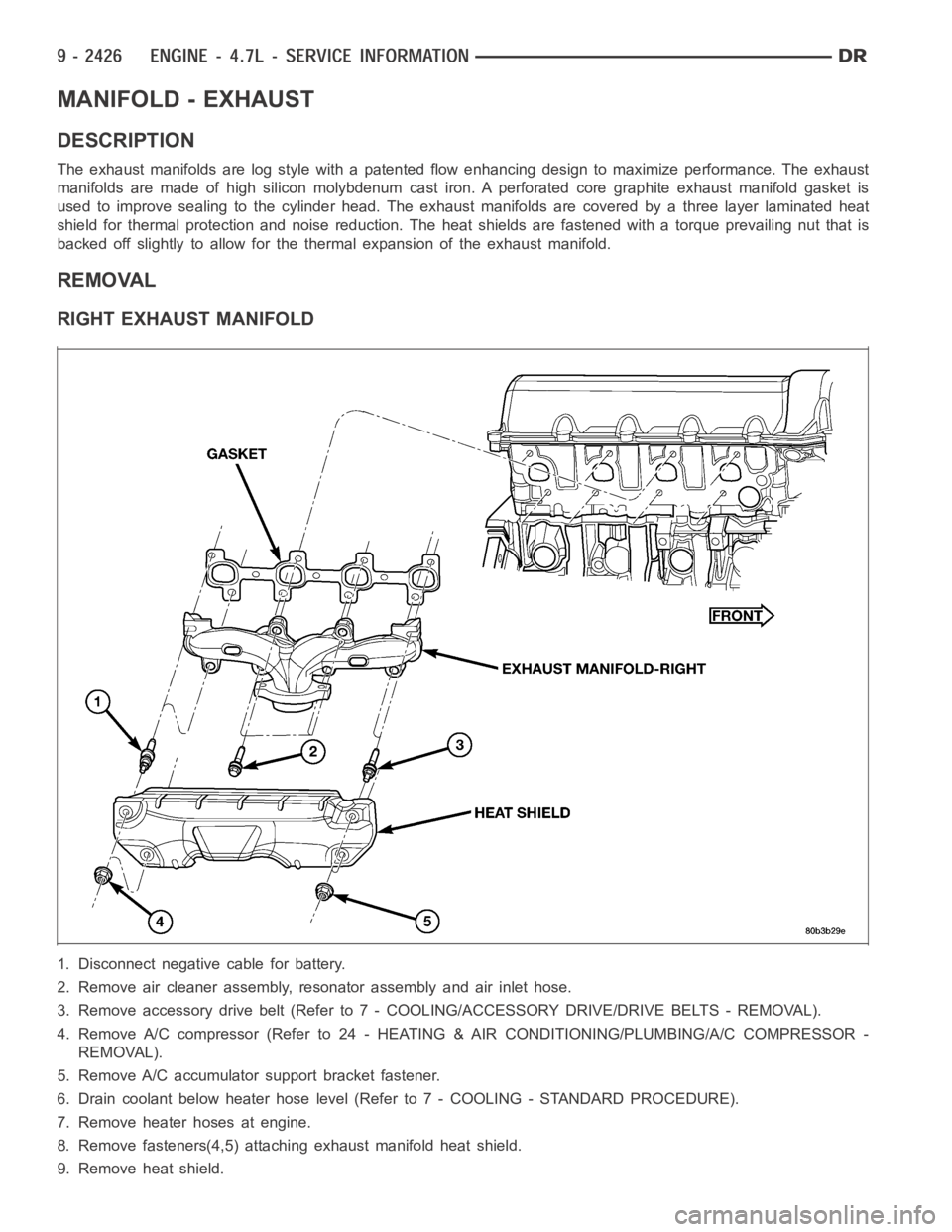
The exhaust manifolds are log style with a patented flow enhancing design to maximize performance. The exhaust
manifolds are made of high silicon molybdenum cast iron. A perforated coregraphite exhaust manifold gasket is
used to improve sealing to the cylinder head. The exhaust manifolds are covered by a three layer laminated heat
shield for thermal protection and noise reduction. The heat shields are fastened with a torque prevailing nut that is
backed off slightly to allow for the thermal expansion of the exhaust manifold.
REMOVAL
RIGHT EXHAUST MANIFOLD
1. Disconnect negative cable for battery.
2. Remove air cleaner assembly, resonator assembly and air inlet hose.
3. Remove accessory drive belt (Refer to 7 - COOLING/ACCESSORY DRIVE/DRIVE BELTS - REMOVAL).
4. Remove A/C compressor (Refer to 24 -HEATING & AIR CONDITIONING/PLUMBING/A/C COMPRESSOR -
REMOVAL).
5. Remove A/C accumulator support bracket fastener.
6. Drain coolant below heater hose level (Refer to 7 - COOLING - STANDARD PROCEDURE).
7. Remove heater hoses at engine.
8. Remove fasteners(4,5) attaching exhaust manifold heat shield.
9. Remove heat shield.