2006 DODGE RAM SRT-10 light
[x] Cancel search: lightPage 1463 of 5267
Possible Causes
(A103) FUSED B+ CIRCUIT
(Z429) BRAKE LAMP SWITCH GROUND CIRCUIT OPEN
BRAKE LAMP SWITCH
(B29) BRAKE SWITCH NO.1 SIGNAL CIRCUIT OPEN
(B29) BRAKE SWITCH NO.1 SIGNAL CIRCUIT SHORT TO GROUND
PCM
Always perform the Pre-Diagnostic Troubleshooting procedure before proceeding. (Refer to 9 - ENGINE -
DIAGNOSIS AND TESTING)
Diagnostic Test
1.SCAN TOOL DOES NOT SHOW BRAKE SW PRESSED OR RELEASED
Ignition on, engine not running.
With the scan tool in Inputs/Outputs, read the Brake Switch state.
While observing the scan tool display, press and release the brake pedal several times.
Does the scan tool display Brake Switch PRESSED and RELEASED?
Ye s>>
The Brake Lamp Switch is operating properly at this time.
Perform the POWERTRAIN VERIFICATION TEST. (Refer to 9 - ENGINE - STANDARD PROCEDURE)
No>>
Go To 2
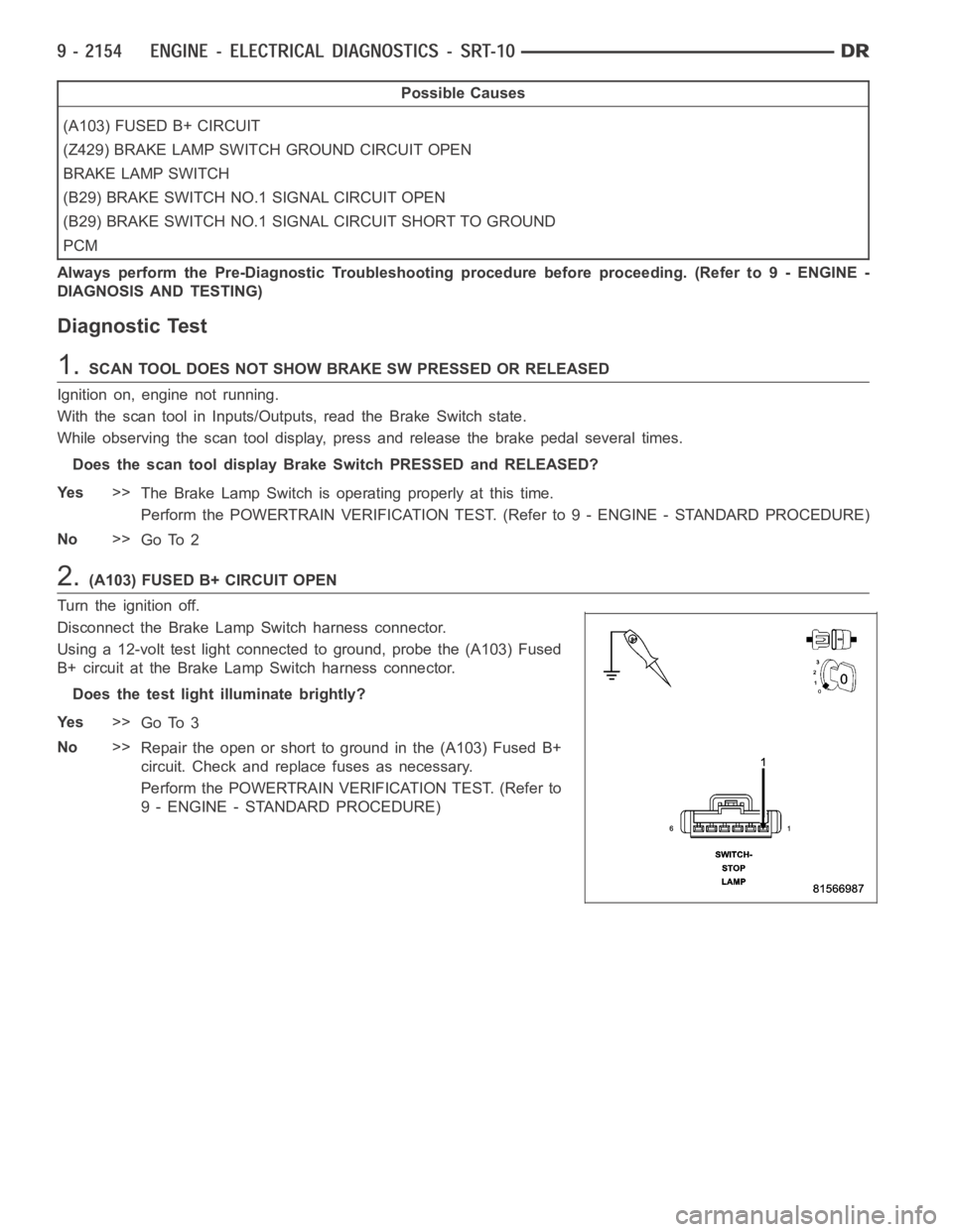
2.(A103) FUSED B+ CIRCUIT OPEN
Turn the ignition off.
Disconnect the Brake Lamp Switch harness connector.
Using a 12-volt test light connected to ground, probe the (A103) Fused
B+ circuit at the Brake Lamp Switch harness connector.
Does the test light illuminate brightly?
Ye s>>
Go To 3
No>>
Repair the open or short to ground in the (A103) Fused B+
circuit. Check and replace fuses as necessary.
Perform the POWERTRAIN VERIFICATION TEST. (Refer to
9 - ENGINE - STANDARD PROCEDURE)
Page 1464 of 5267
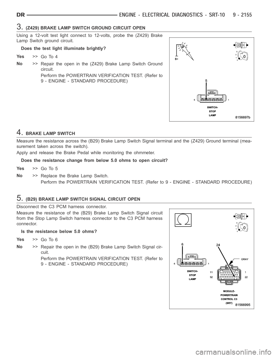
3.(Z429) BRAKE LAMP SWITCH GROUND CIRCUIT OPEN
Using a 12-volt test light connect to 12-volts, probe the (Z429) Brake
Lamp Switch ground circuit.
Does the test light illuminate brightly?
Ye s>>
Go To 4
No>>
Repair the open in the (Z429) Brake Lamp Switch Ground
circuit.
Perform the POWERTRAIN VERIFICATION TEST. (Refer to
9 - ENGINE - STANDARD PROCEDURE)
4.BRAKE LAMP SWITCH
Measure the resistance across the (B29) Brake Lamp Switch Signal terminaland the (Z429) Ground terminal (mea-
surement taken across the switch).
Apply and release the Brake Pedal while monitoring the ohmmeter.
Does the resistance change frombelow 5.0 ohms to open circuit?
Ye s>>
Go To 5
No>>
Replace the Brake Lamp Switch.
Perform the POWERTRAIN VERIFICATION TEST. (Refer to 9 - ENGINE - STANDARD PROCEDURE)
5.(B29) BRAKE LAMP SWITCH SIGNAL CIRCUIT OPEN
Disconnect the C3 PCM harness connector.
Measure the resistance of the (B29) Brake Lamp Switch Signal circuit
from the Stop Lamp Switch harness connector to the C3 PCM harness
connector.
Is the resistance below 5.0 ohms?
Ye s>>
Go To 6
No>>
Repair the open in the (B29) Brake Lamp Switch Signal cir-
cuit.
Perform the POWERTRAIN VERIFICATION TEST. (Refer to
9 - ENGINE - STANDARD PROCEDURE)
Page 1465 of 5267
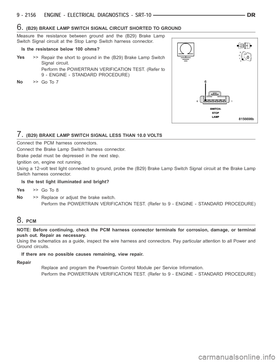
6.(B29) BRAKE LAMP SWITCH SIGNAL CIRCUIT SHORTED TO GROUND
Measure the resistance between ground and the (B29) Brake Lamp
Switch Signal circuit at the Stop Lamp Switch harness connector.
Istheresistancebelow100ohms?
Ye s>>
Repair the short to ground in the (B29) Brake Lamp Switch
Signal circuit.
Perform the POWERTRAIN VERIFICATION TEST. (Refer to
9 - ENGINE - STANDARD PROCEDURE)
No>>
Go To 7
7.(B29) BRAKE LAMP SWITCH SIGNAL LESS THAN 10.0 VOLTS
Connect the PCM harness connectors.
Connect the Brake Lamp Switch harness connector.
Brake pedal must be depressed in the next step.
Ignition on, engine not running.
Using a 12-volt test light connected to ground, probe the (B29) Brake Lamp Switch Signal circuit at the Brake Lamp
Switch harness connector.
Is the test light illuminated and bright?
Ye s>>
Go To 8
No>>
Replace or adjust the brake switch.
Perform the POWERTRAIN VERIFICATION TEST. (Refer to 9 - ENGINE - STANDARD PROCEDURE)
8.PCM
NOTE: Before continuing, check the PCM harness connector terminals for corrosion, damage, or terminal
push out. Repair as necessary.
Using the schematics as a guide, inspect the wire harness and connectors. Pay particular attention to all Power and
Ground circuits.
If there are no possible causes remaining, view repair.
Repair
Replace and program the Powertrain Control Module per Service Information.
Perform the POWERTRAIN VERIFICATION TEST. (Refer to 9 - ENGINE - STANDARD PROCEDURE)
Page 1470 of 5267
4.REFRIGERATION SYSTEM NOT PROPERLY CHARGED
Turn the ignition off.
Verify that the Refrigerant System is properly charged per Service Procedure.
Is the Refrigerant System properly charged?
Ye s>>
Go To 5
No>>
Properly charge the Refrigerant System per Service Information.
Perform BODY VERIFICATION TEST - VER 1.
5.HIGH PRESSURE CUT-OFF SWITCH
Turn the ignition off.
Verify the High Pressure Cut-Off Switch operation per Service Information.
Is the High Pressure Cut-Off Switch OK?
Ye s>>
Go To 6
No>>
Replace the High Pressure Cut-Off Switch.
Perform BODY VERIFICATION TEST - VER 1.
6.LOW PRESSURE SWITCH
Turn the ignition off.
Verify the Low Pressure Switch operation per Service Information.
Is the Low Pressure Switch OK?
Ye s>>
Go To 7
No>>
Replace the Low Pressure Switch.
Perform BODY VERIFICATION TEST - VER 1.
7.A/C CLUTCH COIL
Ignition on, engine not running.
Disconnect the A/C Compressor Clutch harness connector.
Connect a test light between the ground circuit and the A/C Clutch Relay Output circuit.
With the scan tool, actuate the A/C Clutch Relay.
Does the test light illuminate brightly on and off with the relay actuation?
Ye s>>
Replace the A/C Clutch Coil.
Perform BODY VERIFICATION TEST - VER 1.
No>>
Go To 8
8.A/C COMPRESSOR CLUTCH GROUND CIRCUIT OPEN
Turn the ignition off.
Disconnect the A/C Clutch harness connector.
NOTE: Check connectors - Clean/repair as necessary.
Measure the resistance between ground and the A/C Compressor Clutch ground circuit in the A/C Clutch harness
connector.
Is the resistance below 5.0 ohms?
Ye s>>
Go To 9
No>>
Repair the open in the A/C Compressor Clutch ground circuit.
Perform BODY VERIFICATION TEST - VER 1.
Page 1475 of 5267
Replace and program the Powertrain Control Module per Service Information.
Perform the POWERTRAIN VERIFICATION TEST. (Refer to 9 - ENGINE - STANDARD PROCEDURE)
8.GENERATOR BELT CONDITION
Turn the ignition off.
NOTE: Battery condition must be verified prior to this test.
Inspect the Generator Belt tension and condition.
Is the Generator Belt OK?
Ye s>>
Go To 9
No>>
Repair as necessary.
Perform the POWERTRAIN VERIFICATION TEST. (Refer to 9 - ENGINE - STANDARD PROCEDURE)
9.ACTIVE DTC SET
Start the engine.
Turn on all accessories.
Raise engine speed to 2000 RPM for 30 seconds then return to idle.
With the scan tool, read DTCs.
Are there any
Charging SystemTrouble Codes?
Ye s>>
Refer to DTC list for the related Charging DTCs.
Perform the POWERTRAIN VERIFICATION TEST. (Refer to 9 - ENGINE - STANDARD PROCEDURE)
No>>
Go To 10
10.WIRE HARNESS INSPECTION
Ignition on, engine not running.
With the scan tool, actuate the Generator Field Driver.
Using a 12-volt test light, backprobe the Generator Field Driver Terminalat the back of the Generator.
NOTE: The test light should blink On and Off every 1.4 seconds.
While monitoring the 12-volt test light, wiggle the Field Terminals back to the PCM and ASD Relay.
Was there any interruption in the normal cycle of the test light?
Ye s>>
Repair the wire or connector where the wiggling interrupted the voltage cycle.
Perform the POWERTRAIN VERIFICATION TEST. (Refer to 9 - ENGINE - STANDARD PROCEDURE)
No>>
Te s t C o m p l e t e .
Page 1479 of 5267
Possible Causes
(A919) PCM FUSED B+ CIRCUIT
(F202) PCM FUSED IGNITION SWITCH OUTPUT CIRCUIT
(Z130) AND (Z131) PCM GROUND CIRCUITS
Always perform the Pre-Diagnostic Troubleshooting procedure before proceeding. (Refer to 9 - ENGINE -
DIAGNOSIS AND TESTING)
Diagnostic Test
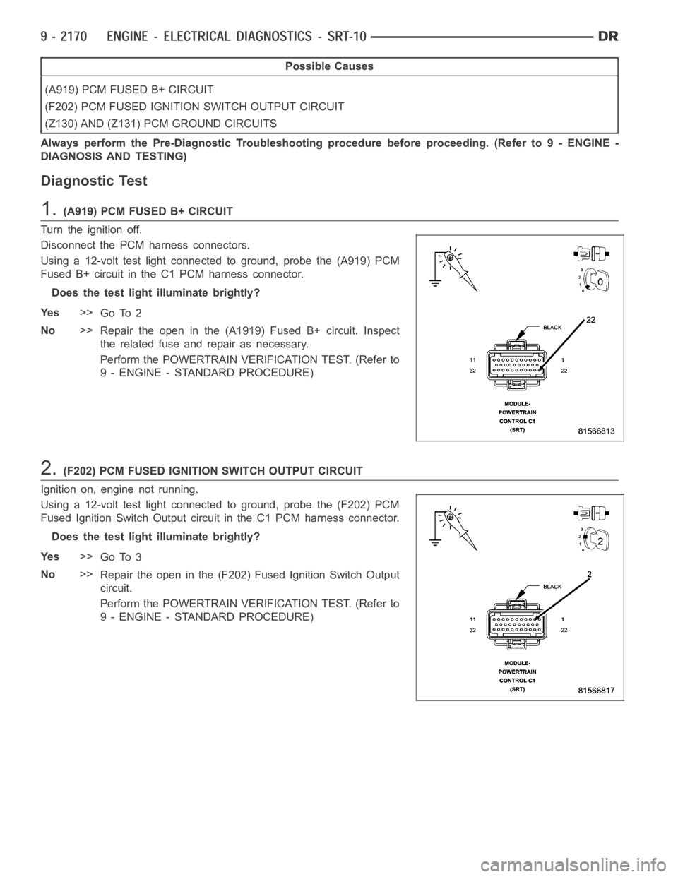
1.(A919) PCM FUSED B+ CIRCUIT
Turn the ignition off.
Disconnect the PCM harness connectors.
Using a 12-volt test light connected to ground, probe the (A919) PCM
Fused B+ circuit in the C1 PCM harness connector.
Does the test light illuminate brightly?
Ye s>>
Go To 2
No>>
Repair the open in the (A1919) Fused B+ circuit. Inspect
the related fuse and repair as necessary.
Perform the POWERTRAIN VERIFICATION TEST. (Refer to
9 - ENGINE - STANDARD PROCEDURE)
2.(F202) PCM FUSED IGNITION SWITCH OUTPUT CIRCUIT
Ignition on, engine not running.
Using a 12-volt test light connected to ground, probe the (F202) PCM
Fused Ignition Switch Output circuit in the C1 PCM harness connector.
Does the test light illuminate brightly?
Ye s>>
Go To 3
No>>
Repair the open in the (F202) Fused Ignition Switch Output
circuit.
Perform the POWERTRAIN VERIFICATION TEST. (Refer to
9 - ENGINE - STANDARD PROCEDURE)
Page 1480 of 5267
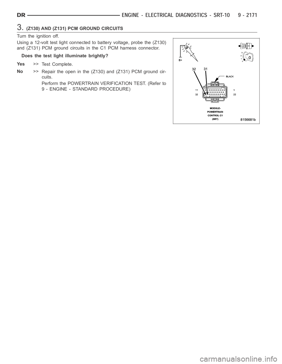
3.(Z130) AND (Z131) PCM GROUND CIRCUITS
Turn the ignition off.
Using a 12-volt test light connected to battery voltage, probe the (Z130)
and (Z131) PCM ground circuits in the C1 PCM harness connector.
Does the test light illuminate brightly?
Ye s>>
Te s t C o m p l e t e .
No>>
Repair the open in the (Z130) and (Z131) PCM ground cir-
cuits.
Perform the POWERTRAIN VERIFICATION TEST. (Refer to
9 - ENGINE - STANDARD PROCEDURE)
Page 1483 of 5267
POWERTRAIN VERIFICATION TEST
For a complete wiring diagramRefer to Section 8W.
Diagnostic Test
1.SELECTING THE PROPER VERIFICATION TEST
The following verification test are for different repairs. Select the appropriate Verification test for the
repair that has been completed.
Speed Control repair
Go To 2
Charging System repair
Go To 3
NVLD System repair
Go To 4
All other repairs
Go To 5
2.POWERTRAIN VERIFICATION TEST 1
NOTE: 1. If this vehicle is equipped with an Electronic Throttle Control system, and the APP Sensors, PCM,
or Throttle Body Assembly have been replaced, use the scan tool to perform the ETC RELEARN function.
NOTE: 2. After completing the Powertrain Verification Test the Transmission Verification Test must be per-
formed.
NOTE: 3. If the PCM has been replaced and the correct VIN and mileage have notbeen programmed, a DTC
will set in the ABS Module, Airbag Module and the SKIM/SKREEM.
NOTE: 4. If the vehicle is equipped with a Sentry Key Remote Entry, Secret Key data must be updated. Refer
to the Service Information for the PCM, SKIM/SKREEM and the Transponder (ignition key) for programming
information. Using the scan tool, program the Secret Key information intothe PCM using the PCM replaced
function under the WCM menu.
5. Inspect the vehicle to make sure that all engine components are properlyinstalled and connected.
6. Connect the scan tool to the data link connector and erase all codes.
7. Turn the speed control ON (if equipped, cruise light will be on).
8. Depress and release the SET Switch when the vehicle speed is greater than35 MPH. The speed control should
engage and hold the selected speed.
9. Press and hold the RESUME/ACCEL Switch. The vehicle speed should increase by at least 2 MPH.
10. Press and hold the COAST switch. The vehicle speed should decrease.
11. Using caution, press and release the brake pedal. The speed control should disengage.
12. Bring the vehicle speed back up to 35 MPH.
13. Press the RESUME/ACCEL switch. The speed control should resume the previously set speed.
14. Hold down the SET switch. The vehicle should decelerate.
15. Make sure vehicle speed is greater than 35 mph and release the SET Switch. The vehicle should adjust and set
a new vehicle speed.
16. Press and release the CANCEL switch. The speed control should disengage.
17. Bring the vehicle speed back up above 35 mph and engage speed control.
18. Turn the Speed Control Off. (Cruise light will be off). The speed control should disengage.
NOTE: OVERSHOOT/UNDERSHOOT FOLLOWING SPEED CONTROL SET.
19. If the vehicle operator repeatedly presses and releases the SET buttonwith their foot off of the accelerator
(referred to as
lift foot set), the vehicle may accelerate and exceed the desired set speed by up to 5 mph (8km/h).
20. It may also decelerate to less than the desired set speed, before finally achieving the desired set speed.
21. The Speed Control System has an adaptive strategy that compensates forvehicle-to-vehicle variations in speed
control cable lengths.
22. When the speed control is set with the vehicles operators foot off of theaccelerator pedal, the speed control
thinks there is excessive speed control cable slack and adapts accordingly.