2006 DODGE RAM SRT-10 light
[x] Cancel search: lightPage 1588 of 5267
DIAGNOSIS AND TESTING - CHECKING ENGINE OIL PRESSURE
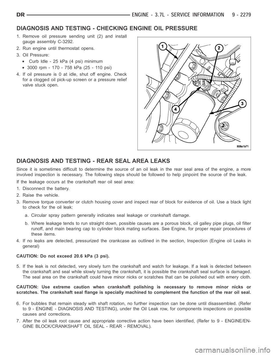
1. Remove oil pressure sending unit (2) and install
gauge assembly C-3292.
2. Run engine until thermostat opens.
3. Oil Pressure:
Curb Idle - 25 kPa (4 psi) minimum
3000 rpm - 170 - 758 kPa (25 - 110 psi)
4. If oil pressure is 0 at idle, shut off engine. Check
for a clogged oil pick-up screen or a pressure relief
valve stuck open.
DIAGNOSIS AND TESTING - REAR SEAL AREA LEAKS
Since it is sometimes difficult to determine the source of an oil leak in therear seal area of the engine, a more
involved inspection is necessary. The following steps should be followedto help pinpoint the source of the leak.
If the leakage occurs at the crankshaft rear oil seal area:
1. Disconnect the battery.
2. Raise the vehicle.
3. Remove torque converter or clutch housing cover and inspect rear of block for evidence of oil. Use a black light
to check for the oil leak:
a. Circular spray pattern generally indicates seal leakage or crankshaftdamage.
b. Where leakage tends to run straight down, possible causes are a porous block, oil galley pipe plugs, oil filter
runoff, and main bearing cap to cylinder block mating surfaces. See Engine, for proper repair procedures of
these items.
4. If no leaks are detected, pressurized the crankcase as outlined in the section, Inspection (Engine oil Leaks in
general)
CAUTION: Do not exceed 20.6 kPa (3 psi).
5. If the leak is not detected, very slowly turn the crankshaft and watch forleakage. If a leak is detected between
the crankshaft and seal while slowly turning the crankshaft, it is possible the crankshaft seal surface is damaged.
The seal area on the crankshaft could have minor nicks or scratches that canbe polished out with emery cloth.
CAUTION: Use extreme caution when crankshaft polishing is necessary to remove minor nicks or
scratches. The crankshaft seal flange is specially machined to complement the function of the rear oil seal.
6. For bubbles that remain steady with shaft rotation, no further inspection can be done until disassembled. (Refer
to 9 - ENGINE - DIAGNOSIS AND TESTING), under the Oil Leak row, for components inspections on possible
causes and corrections.
7. After the oil leak root cause and appropriate corrective action have been identified, (Refer to 9 - ENGINE/EN-
GINE BLOCK/CRANKSHAFT OIL SEAL - REAR - REMOVAL).
Page 1597 of 5267
FILTER-ENGINE OIL
REMOVAL
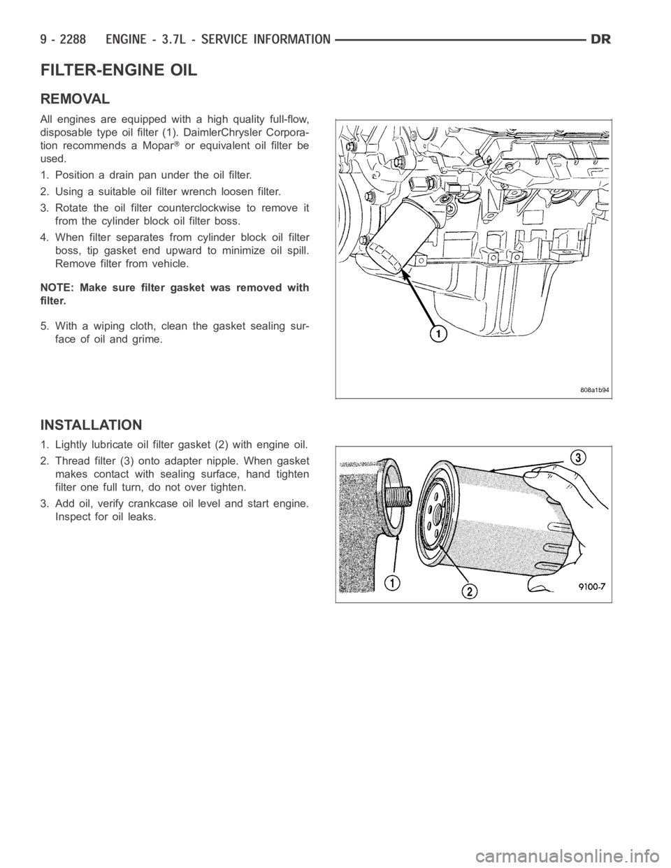
All engines are equipped with a high quality full-flow,
disposable type oil filter (1). DaimlerChrysler Corpora-
tion recommends a Mopar
or equivalent oil filter be
used.
1. Position a drain pan under the oil filter.
2. Using a suitable oil filter wrench loosen filter.
3. Rotate the oil filter counterclockwise to remove it
from the cylinder block oil filter boss.
4. When filter separates from cylinder block oil filter
boss, tip gasket end upward to minimize oil spill.
Remove filter from vehicle.
NOTE: Make sure filter gasket was removed with
filter.
5. With a wiping cloth, clean the gasket sealing sur-
face of oil and grime.
INSTALLATION
1. Lightly lubricate oil filter gasket (2) with engine oil.
2. Thread filter (3) onto adapter nipple. When gasket
makes contact with sealing surface, hand tighten
filter one full turn, do not over tighten.
3. Add oil, verify crankcase oil level and start engine.
Inspect for oil leaks.
Page 1603 of 5267
MANIFOLD-EXHAUST
DESCRIPTION
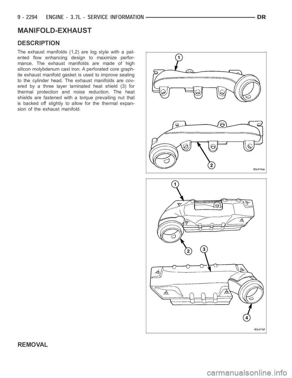
The exhaust manifolds (1,2) are log style with a pat-
ented flow enhancing design to maximize perfor-
mance. The exhaust manifolds are made of high
silicon molybdenum cast iron. A perforated core graph-
ite exhaust manifold gasket is used to improve sealing
to the cylinder head. The exhaust manifolds are cov-
ered by a three layer laminated heat shield (3) for
thermal protection and noise reduction. The heat
shields are fastened witha torque prevailing nut that
is backed off slightly to allow for the thermal expan-
sion of the exhaust manifold.
REMOVAL
Page 1606 of 5267
VALVE TIMING
DESCRIPTION
The timing drive system has been designed to provide quiet performance andreliability to support anon-free
wheelingengine. Specifically the intake valves are non-free wheeling and can be easily damaged with forceful
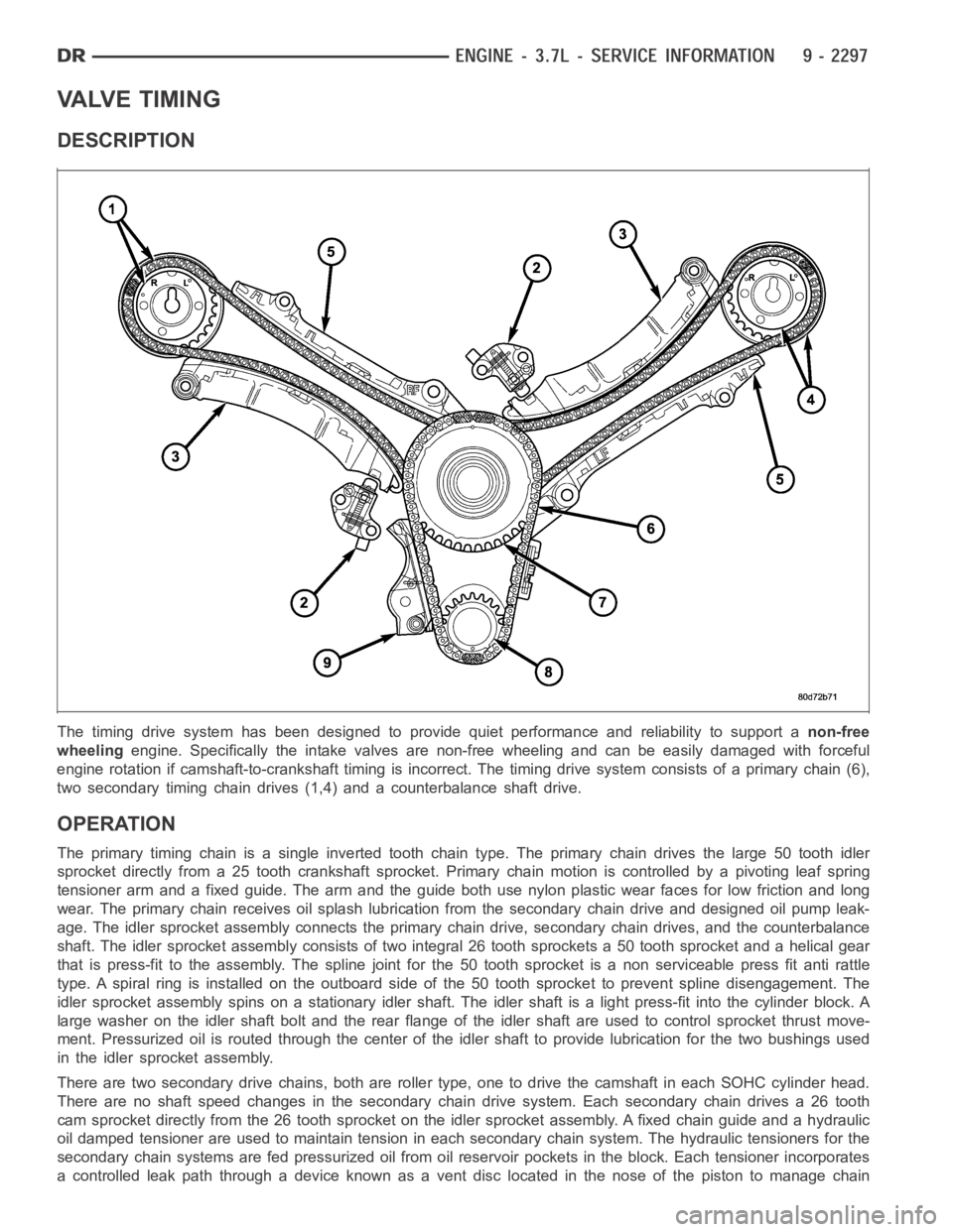
engine rotation if camshaft-to-crankshaft timing is incorrect. The timing drive system consists of a primary chain (6),
two secondary timing chain drives (1,4) and a counterbalance shaft drive.
OPERATION
The primary timing chain is a single inverted tooth chain type. The primarychaindrivesthelarge50toothidler
sprocket directly from a 25 tooth crankshaft sprocket. Primary chain motion is controlled by a pivoting leaf spring
tensioner arm and a fixed guide. The arm and the guide both use nylon plasticwear faces for low friction and long
wear. The primary chain receives oil splash lubrication from the secondary chain drive and designed oil pump leak-
age. The idler sprocket assembly connects the primary chain drive, secondary chain drives, and the counterbalance
shaft. The idler sprocket assembly consists of two integral 26 tooth sprockets a 50 tooth sprocket and a helical gear
that is press-fit to the assembly. Thespline joint for the 50 tooth sprocket is a non serviceable press fit anti rattle
type. A spiral ring is installed on the outboard side of the 50 tooth sprocket to prevent spline disengagement. The
idler sprocket assembly spins on a stationary idler shaft. The idler shaftis a light press-fit into the cylinder block. A
large washer on the idler shaft bolt and the rear flange of the idler shaft are used to control sprocket thrust move-
ment. Pressurized oil is routed through the center of the idler shaft to provide lubrication for the two bushings used
in the idler sprocket assembly.
There are two secondary drive chains, both are roller type, one to drive thecamshaft in each SOHC cylinder head.
There are no shaft speed changes in the secondary chain drive system. Each secondary chain drives a 26 tooth
cam sprocket directly from the 26 tooth sprocket on the idler sprocket assembly. A fixed chain guide and a hydraulic
oil damped tensioner are used to maintain tension in each secondary chain system. The hydraulic tensioners for the
secondary chain systems are fed pressurized oil from oil reservoir pockets in the block. Each tensioner incorporates
a controlled leak path through a device known as a vent disc located in the nose of the piston to manage chain
Page 1619 of 5267
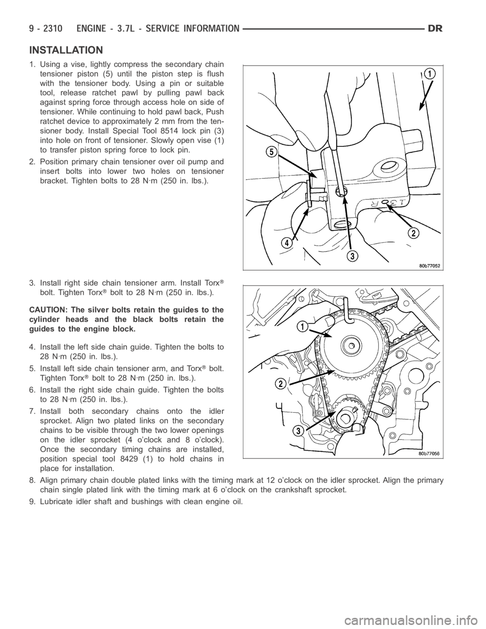
INSTALLATION
1. Using a vise, lightly compress the secondary chain
tensioner piston (5) until the piston step is flush
with the tensioner body. Using a pin or suitable
tool, release ratchet pawl by pulling pawl back
against spring force through access hole on side of
tensioner. While continuing to hold pawl back, Push
ratchet device to approximately 2 mm from the ten-
sioner body. Install Special Tool 8514 lock pin (3)
into hole on front of tensioner. Slowly open vise (1)
to transfer piston spring force to lock pin.
2. Position primary chain tensioner over oil pump and
insert bolts into lower two holes on tensioner
bracket. Tighten bolts to 28 Nꞏm (250 in. lbs.).
3. Install right side chain tensioner arm. Install Torx
bolt. Tighten Torxbolt to 28 Nꞏm (250 in. lbs.).
CAUTION: The silver bolts retain the guides to the
cylinder heads and the black bolts retain the
guides to the engine block.
4. Install the left side chain guide. Tighten the bolts to
28 Nꞏm (250 in. lbs.).
5. Install left side chain tensioner arm, and Torx
bolt.
Tighten Torx
bolt to 28 Nꞏm (250 in. lbs.).
6. Install the right side chain guide. Tighten the bolts
to 28 Nꞏm (250 in. lbs.).
7. Install both secondary chains onto the idler
sprocket. Align two plated links on the secondary
chains to be visible through the two lower openings
on the idler sprocket (4 o’clock and 8 o’clock).
Once the secondary timing chains are installed,
position special tool 8429 (1) to hold chains in
place for installation.
8. Align primary chain double platedlinks with the timing mark at 12 o’clock on the idler sprocket. Align the primary
chain single plated link with the timing mark at 6 o’clock on the crankshaftsprocket.
9. Lubricate idler shaft and bushings with clean engine oil.
Page 1620 of 5267
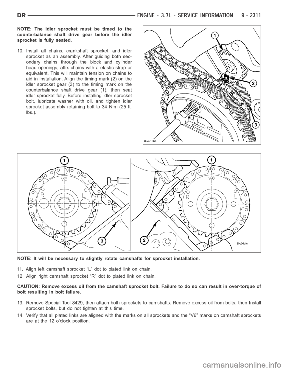
NOTE: The idler sprocket must be timed to the
counterbalance shaft drive gear before the idler
sprocket is fully seated.
10. Install all chains, crankshaft sprocket, and idler
sprocket as an assembly. After guiding both sec-
ondary chains through the block and cylinder
head openings, affix chains with a elastic strap or
equivalent. This will maintain tension on chains to
aid in installation. Align the timing mark (2) on the
idler sprocket gear (3) to the timing mark on the
counterbalance shaft drive gear (1), then seat
idler sprocket fully. Before installing idler sprocket
bolt, lubricate washer with oil, and tighten idler
sprocketassemblyretainingboltto34Nꞏm(25ft.
lbs.).
NOTE: It will be necessary to slightly rotate camshafts for sprocket installation.
11. Align left camshaft sprocket “L” dot to plated link on chain.
12. Align right camshaft sprocket “R” dot to plated link on chain.
CAUTION: Remove excess oil from the camshaft sprocket bolt. Failure to do so can result in over-torque of
bolt resulting in bolt failure.
13. Remove Special Tool 8429, then attach both sprockets to camshafts. Remove excess oil from bolts, then Install
sprocket bolts, but do not tighten at this time.
14. Verify that all plated links are aligned with the marks on all sprocketsand the “V6” marks on camshaft sprockets
are at the 12 o’clock position.
Page 1625 of 5267
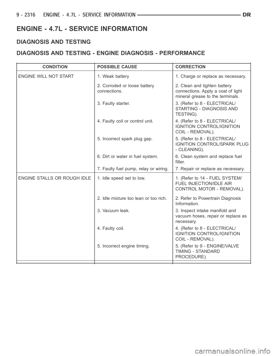
ENGINE - 4.7L - SERVICE INFORMATION
DIAGNOSIS AND TESTING
DIAGNOSIS AND TESTING - ENGINE DIAGNOSIS - PERFORMANCE
CONDITION POSSIBLE CAUSE CORRECTION
ENGINE WILL NOT START 1. Weak battery 1. Charge or replace as necessary.
2. Corroded or loose battery
connections.2. Clean and tighten battery
connections. Apply a coat of light
mineral grease to the terminals.
3. Faulty starter. 3. (Refer to 8 - ELECTRICAL/
STARTING - DIAGNOSIS AND
TESTING).
4. Faulty coil or control unit. 4. (Refer to 8 - ELECTRICAL/
IGNITION CONTROL/IGNITION
COIL - REMOVAL).
5. Incorrect spark plug gap. 5. (Refer to 8 - ELECTRICAL/
IGNITION CONTROL/SPARK PLUG
- CLEANING).
6. Dirt or water in fuel system. 6. Clean system and replace fuel
filter.
7. Faulty fuel pump, relay or wiring. 7. Repair or replace as necessary.
ENGINE STALLS OR ROUGH IDLE 1. Idle speed set to low. 1. (Refer to 14 - FUEL SYSTEM/
FUEL INJECTION/IDLE AIR
CONTROL MOTOR - REMOVAL).
2. Idle mixture too lean or too rich. 2. Refer to Powertrain Diagnosis
Information.
3. Vacuum leak. 3. Inspect intake manifold and
vacuum hoses, repair or replace as
necessary.
4. Faulty coil. 4. (Refer to 8 - ELECTRICAL/
IGNITION CONTROL/IGNITION
COIL - REMOVAL).
5. Incorrect engine timing. 5. (Refer to 9 - ENGINE/VALVE
TIMING - STANDARD
PROCEDURE).
Page 1634 of 5267
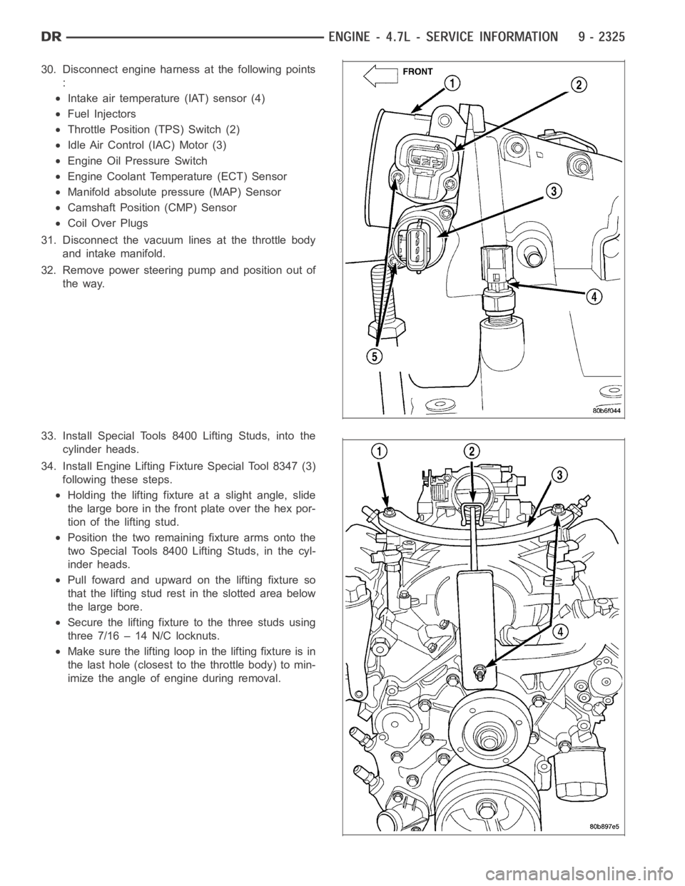
30. Disconnect engine harness at the following points
:
Intake air temperature (IAT) sensor (4)
Fuel Injectors
Throttle Position (TPS) Switch (2)
Idle Air Control (IAC) Motor (3)
Engine Oil Pressure Switch
Engine Coolant Temperature (ECT) Sensor
Manifold absolute pressure (MAP) Sensor
Camshaft Position (CMP) Sensor
Coil Over Plugs
31. Disconnect the vacuum lines at the throttle body
and intake manifold.
32. Remove power steering pump and position out of
the way.
33. Install Special Tools 8400 Lifting Studs, into the
cylinder heads.
34. Install Engine Lifting Fixture Special Tool 8347 (3)
following these steps.
Holding the lifting fixture at a slight angle, slide
the large bore in the front plate over the hex por-
tion of the lifting stud.
Position the two remaining fixture arms onto the
two Special Tools 8400 Lifting Studs, in the cyl-
inder heads.
Pull foward and upward on the lifting fixture so
that the lifting stud rest in the slotted area below
the large bore.
Secure the lifting fixture to the three studs using
three 7/16 – 14 N/C locknuts.
Make sure the lifting loop in the lifting fixture is in
the last hole (closest to the throttle body) to min-
imize the angle of engine during removal.