2006 DODGE RAM SRT-10 light
[x] Cancel search: lightPage 3069 of 5267
TORQUE CONVERTER CLUTCH (TCC)
In a standard torque converter, the impeller and tur-
bine are rotating at about the same speed and the
stator is freewheeling, providing no torque multiplica-
tion. By applying the turbine’s piston and friction mate-
rial to the front cover, a total converter engagement
can be obtained. The result of this engagement is a
direct 1:1 mechanical link between the engine and the
transmission.
The clutch can be engaged in second, third, fourth,
and fifth (if appicable) gear ranges depending on over-
drive control switch position. If the overdrive control
switch is in the normal ON position, the clutch will
engage after the shift to fourth gear. If the control
switch is in the OFF position, the clutch will engage
after the shift to third gear.
The TCM controls the torque converter by way of
internal logic software. The programming of the soft-
ware provides the TCM with control over the L/R-CC
Solenoid. There are four output logic states that can
be applied as follows:
No EMCC
Partial EMCC
Full EMCC
Gradual-to-no EMCC
NO EMCC
Under No EMCC conditions, the L/R Solenoid is OFF. There are several conditions that can result in NO EMCC
operations. No EMCC can be initiated due to a fault in the transmission or because the TCM does not see the need
for EMCC under current driving conditions.
PARTIAL EMCC
Partial EMCC operation modulates the L/R Solenoid (duty cycle) to obtain partial torque converter clutch application.
Partial EMCC operation is maintaineduntil Full EMCC is called for and actuated. During Partial EMCC some slip
does occur. Partial EMCC will usually occur at low speeds, low load and light throttle situations.
FULL EMCC
During Full EMCC operation, the TCM increases the L/R Solenoid duty cycle to full ON after Partial EMCC control
brings the engine speed within the desired slip range of transmission input speed relative to engine rpm.
GRADUAL-TO-NO EMCC
This operation is to soften the change from Full or Partial EMCC to No EMCC. This is done at mid-throttle by
decreasing the L/R Solenoid duty cycle.
REMOVAL
1. Remove transmission and torque converter from vehicle. (Refer to 21 - TRANSMISSION/AUTOMATIC - 45RFE/
545RFE - REMOVAL)
2. Place a suitable drain pan under the converter housing end of the transmission.
CAUTION: Verify that transmission is secure on the lifting device or work surface, the center of gravity of
the transmission will shift when the torque converter is removed creatingan unstable condition. The torque
converter is a heavy unit. Use caution when separating the torque converter from the transmission.
3. Pull the torque converter forward until the center hub clears the oil pumpseal.
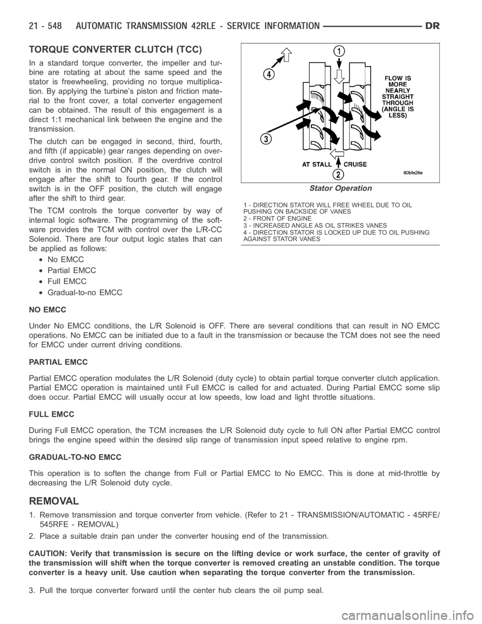
Stator Operation
1 - DIRECTION STATOR WILL FREE WHEEL DUE TO OIL
PUSHING ON BACKSIDE OF VANES
2-FRONTOFENGINE
3 - INCREASED ANGLE AS OIL STRIKES VANES
4 - DIRECTION STATOR IS LOCKED UP DUE TO OIL PUSHING
AGAINST STATOR VANES
Page 3071 of 5267
SWITCH-TOW/HAUL OVERDRIVE
DESCRIPTION
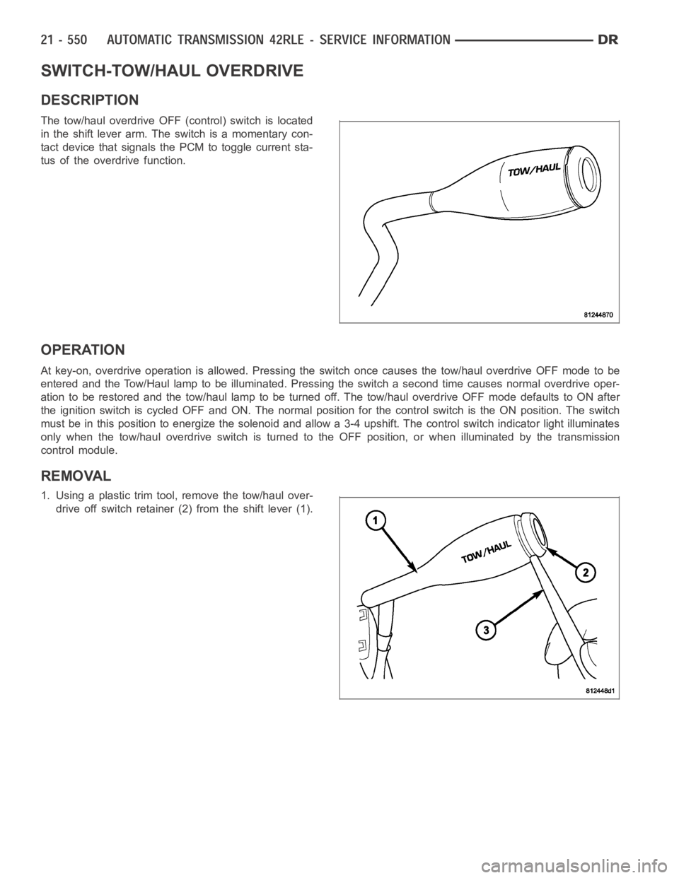
The tow/haul overdrive OFF (control) switch is located
in the shift lever arm. The switch is a momentary con-
tact device that signals the PCM to toggle current sta-
tus of the overdrive function.
OPERATION
At key-on, overdrive operation is allowed. Pressing the switch once causes the tow/haul overdrive OFF mode to be
entered and the Tow/Haul lamp to be illuminated. Pressing the switch a second time causes normal overdrive oper-
ationtoberestoredandthetow/haullamptobeturnedoff.Thetow/hauloverdrive OFF mode defaults to ON after
the ignition switch is cycled OFF and ON. The normal position for the control switch is the ON position. The switch
must be in this position to energize the solenoid and allow a 3-4 upshift. The control switch indicator light illuminates
only when the tow/haul overdrive switch is turned to the OFF position, or when illuminated by the transmission
control module.
REMOVAL
1. Using a plastic trim tool, remove the tow/haul over-
drive off switch retainer (2) from the shift lever (1).
Page 3083 of 5267
CONVERTER CLUTCH CONTROL VALVE
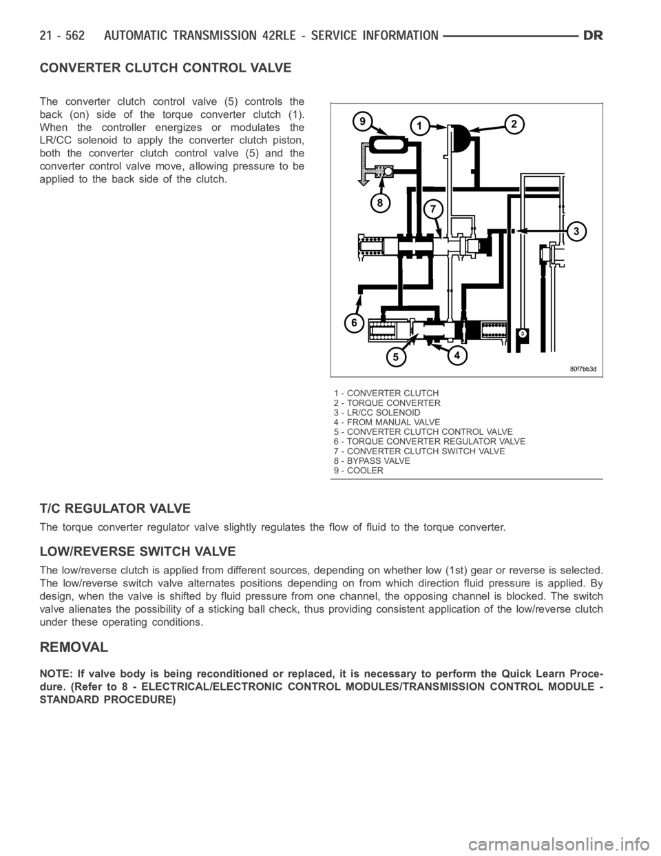
The converter clutch control valve (5) controls the
back (on) side of the torque converter clutch (1).
When the controller energizes or modulates the
LR/CC solenoid to apply the converter clutch piston,
both the converter clutch control valve (5) and the
converter control valve move, allowing pressure to be
applied to the back side of the clutch.
T/C REGULATOR VALVE
The torque converter regulator valve slightly regulates the flow of fluidto the torque converter.
LOW/REVERSE SWITCH VALVE
The low/reverse clutch is applied from different sources, depending on whether low (1st) gear or reverse is selected.
The low/reverse switch valve alternates positions depending on from which direction fluid pressure is applied. By
design, when the valve is shifted by fluid pressure from one channel, the opposing channel is blocked. The switch
valve alienates the possibility of a sticking ball check, thus providing consistent application of the low/reverse clutch
under these operating conditions.
REMOVAL
NOTE: If valve body is being reconditioned or replaced, it is necessary to perform the Quick Learn Proce-
dure. (Refer to 8 - ELECTRICAL/ELECTRONIC CONTROL MODULES/TRANSMISSIONCONTROL MODULE -
STANDARD PROCEDURE)
1 - CONVERTER CLUTCH
2 - TORQUE CONVERTER
3 - LR/CC SOLENOID
4 - FROM MANUAL VALVE
5 - CONVERTER CLUTCH CONTROL VALVE
6 - TORQUE CONVERTER REGULATOR VALVE
7 - CONVERTER CLUTCH SWITCH VALVE
8 - BYPASS VALVE
9 - COOLER
Page 3112 of 5267
3.CONDITION P0562 PRESENT
With the scan tool, read Transmission DTCs.
With the scan tool, Check the STARTS SINCE SET counter for P0562.
NOTE: This counter only applies to the last DTC set.
Is the STARTS SINCE SET counter set at 0?
Ye s>>
Go To 4
No>>
Go To 7
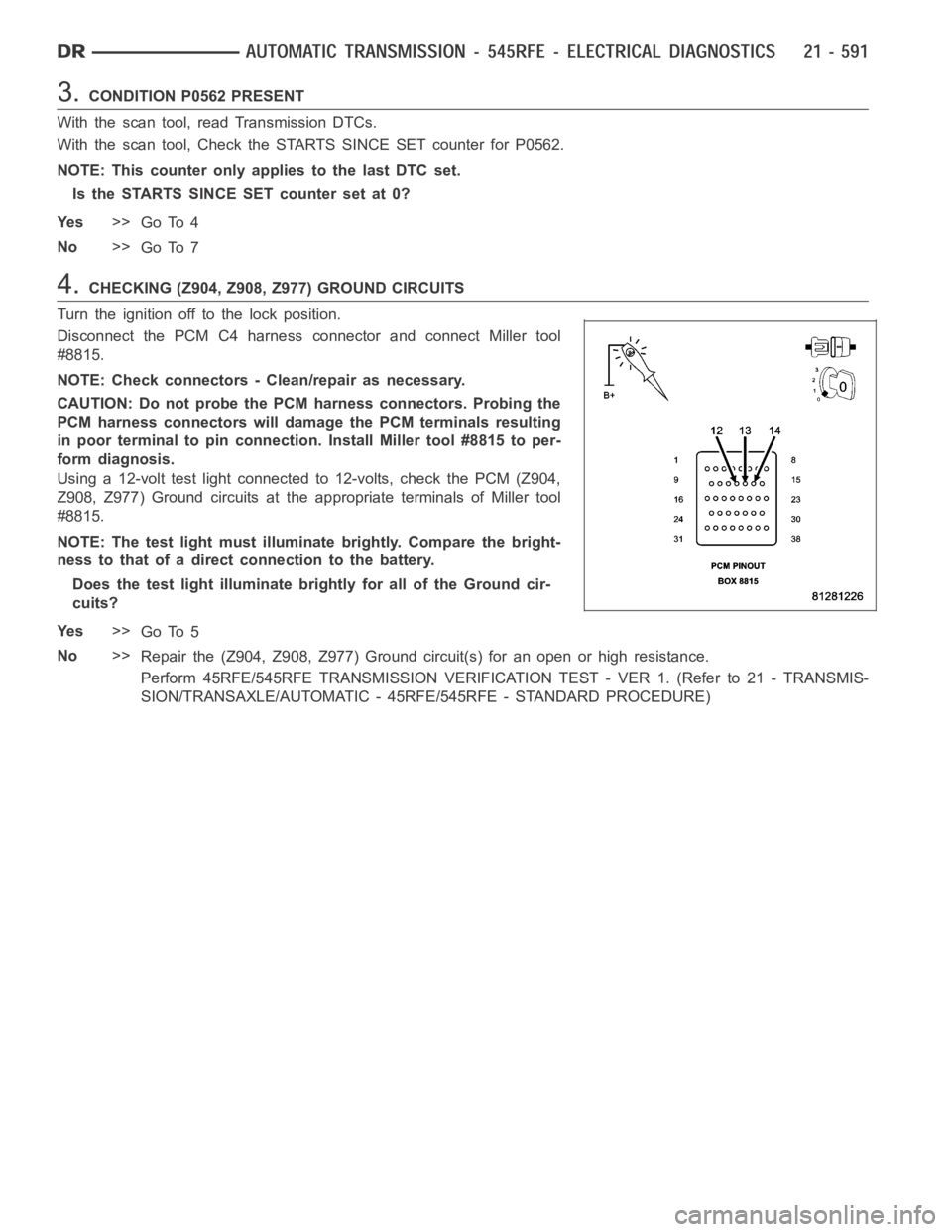
4.CHECKING (Z904, Z908, Z977) GROUND CIRCUITS
Turn the ignition off to the lock position.
Disconnect the PCM C4 harness connector and connect Miller tool
#8815.
NOTE: Check connectors - Clean/repair as necessary.
CAUTION: Do not probe the PCM harness connectors. Probing the
PCM harness connectors will damage the PCM terminals resulting
in poor terminal to pin connection. Install Miller tool #8815 to per-
form diagnosis.
Using a 12-volt test light connected to 12-volts, check the PCM (Z904,
Z908, Z977) Ground circuits at the appropriate terminals of Miller tool
#8815.
NOTE: The test light must illuminate brightly. Compare the bright-
ness to that of a direct connection to the battery.
Does the test light illuminate brightly for all of the Ground cir-
cuits?
Ye s>>
Go To 5
No>>
Repair the (Z904, Z908, Z977) Ground circuit(s) for an open or high resistance.
Perform 45RFE/545RFE TRANSMISSION VERIFICATION TEST - VER 1. (Refer to 21- TRANSMIS-
SION/TRANSAXLE/AUTOMATIC - 45RFE/545RFE - STANDARD PROCEDURE)
Page 3113 of 5267
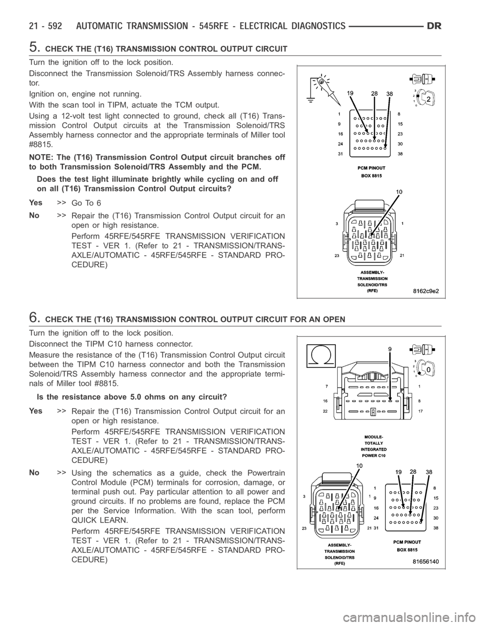
5.CHECK THE (T16) TRANSMISSION CONTROL OUTPUT CIRCUIT
Turn the ignition off to the lock position.
Disconnect the Transmission Solenoid/TRS Assembly harness connec-
tor.
Ignition on, engine not running.
With the scan tool in TIPM, actuate the TCM output.
Using a 12-volt test light connected to ground, check all (T16) Trans-
mission Control Output circuits at the Transmission Solenoid/TRS
Assembly harness connector and the appropriate terminals of Miller tool
#8815.
NOTE: The (T16) Transmission Control Output circuit branches off
to both Transmission Solenoid/TRS Assembly and the PCM.
Does the test light illuminate brightly while cycling on and off
on all (T16) Transmission Control Output circuits?
Ye s>>
Go To 6
No>>
Repair the (T16) Transmission Control Output circuit for an
open or high resistance.
Perform 45RFE/545RFE TRANSMISSION VERIFICATION
TEST - VER 1. (Refer to 21 - TRANSMISSION/TRANS-
AXLE/AUTOMATIC - 45RFE/545RFE - STANDARD PRO-
CEDURE)
6.CHECK THE (T16) TRANSMISSION CONTROL OUTPUT CIRCUIT FOR AN OPEN
Turn the ignition off to the lock position.
Disconnect the TIPM C10 harness connector.
Measure the resistance of the (T16) Transmission Control Output circuit
between the TIPM C10 harness connector and both the Transmission
Solenoid/TRS Assembly harness connector and the appropriate termi-
nals of Miller tool #8815.
Is the resistance above 5.0 ohms on any circuit?
Ye s>>
Repair the (T16) Transmission Control Output circuit for an
open or high resistance.
Perform 45RFE/545RFE TRANSMISSION VERIFICATION
TEST - VER 1. (Refer to 21 - TRANSMISSION/TRANS-
AXLE/AUTOMATIC - 45RFE/545RFE - STANDARD PRO-
CEDURE)
No>>
Using the schematics as a guide, check the Powertrain
Control Module (PCM) terminals for corrosion, damage, or
terminal push out. Pay particular attention to all power and
ground circuits. If no problems are found, replace the PCM
per the Service Information.With the scan tool, perform
QUICK LEARN.
Perform 45RFE/545RFE TRANSMISSION VERIFICATION
TEST - VER 1. (Refer to 21 - TRANSMISSION/TRANS-
AXLE/AUTOMATIC - 45RFE/545RFE - STANDARD PRO-
CEDURE)
Page 3115 of 5267
P0602-CONTROL MODULE PROGRAMMING ERROR/NOT PROGRAMMED
For a complete wiring diagramRefer to Section 8W
Theory of Operation
The controller is programmed during manufacturing with generic softwareto facilitate testing. However, generic soft-
ware does not have the proper calibrations to control a transmission in a vehicle. The check for generic software is
made at power-up. If generic software is found , the MIL will light immediately and the MIL will stay on even if the
fault is cleared, until the proper software is installed. Note: Transmission will be placed in limp-in mode.
When Monitored:
Check for generic software is made at power-up
Set Condition:
If generic software is found, the MIL will light immediately. This DTC is designed to inform the technician that
the controller still has generic software installed.
Possible Causes
PCM - PROGRAMMING ERROR
Always perform the Pre-Diagnostic Troubleshooting procedure before proceeding. (Refer to 21 - TRANSMIS-
SION/TRANSAXLE/AUTOMATIC - 45RFE/545RFE - STANDARD PROCEDURE)
Diagnostic Test
1.CONTROL MODULE PROGRAMMING ERROR
NOTE: Controller is programmed with generic software and will not allow the correct vehicle Powertrain
management.
With the scan tool.
Record the vehicles controller part number.
Select Use Controller Part Number under the Flash Tab.
Flash the controller with the correct software.
Verify the controller flashed successfully.
Te s t C o m p l e t e
Perform 45RFE/545RFE TRANSMISSION VERIFICATION TEST - VER 1. (Refer to 21- TRANSMIS-
SION/TRANSAXLE/AUTOMATIC - 45RFE/545RFE - STANDARD PROCEDURE)
Page 3307 of 5267
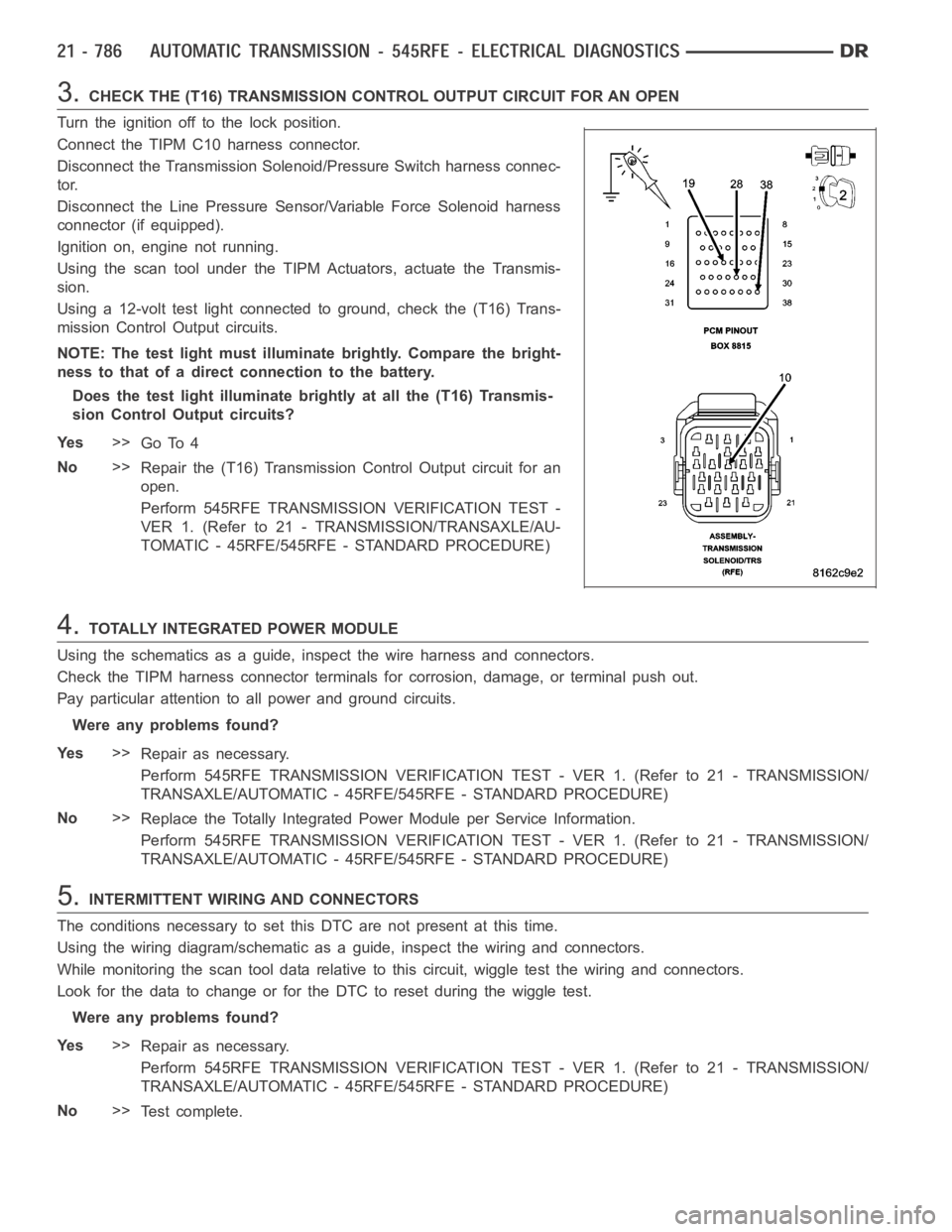
3.CHECK THE (T16) TRANSMISSION CONTROL OUTPUT CIRCUIT FOR AN OPEN
Turn the ignition off to the lock position.
Connect the TIPM C10 harness connector.
Disconnect the Transmission Solenoid/Pressure Switch harness connec-
tor.
Disconnect the Line Pressure Sensor/Variable Force Solenoid harness
connector (if equipped).
Ignition on, engine not running.
Using the scan tool under the TIPM Actuators, actuate the Transmis-
sion.
Using a 12-volt test light connected to ground, check the (T16) Trans-
mission Control Output circuits.
NOTE: The test light must illuminate brightly. Compare the bright-
ness to that of a direct connection to the battery.
Does the test light illuminate brightly at all the (T16) Transmis-
sion Control Output circuits?
Ye s>>
Go To 4
No>>
Repair the (T16) Transmission Control Output circuit for an
open.
Perform 545RFE TRANSMISSION VERIFICATION TEST -
VER 1. (Refer to 21 - TRANSMISSION/TRANSAXLE/AU-
TOMATIC - 45RFE/545RFE - STANDARD PROCEDURE)
4.TOTALLY INTEGRATED POWER MODULE
Using the schematics as a guide, inspect the wire harness and connectors.
Check the TIPM harness connector terminals for corrosion, damage, or terminal push out.
Pay particular attention to all power and ground circuits.
Were any problems found?
Ye s>>
Repair as necessary.
Perform 545RFE TRANSMISSION VERIFICATION TEST - VER 1. (Refer to 21 - TRANSMISSION/
TRANSAXLE/AUTOMATIC - 45RFE/545RFE - STANDARD PROCEDURE)
No>>
Replace the Totally Integrated Power Module per Service Information.
Perform 545RFE TRANSMISSION VERIFICATION TEST - VER 1. (Refer to 21 - TRANSMISSION/
TRANSAXLE/AUTOMATIC - 45RFE/545RFE - STANDARD PROCEDURE)
5.INTERMITTENT WIRING AND CONNECTORS
The conditions necessary to set this DTC are not present at this time.
Using the wiring diagram/schematic as a guide, inspect the wiring and connectors.
While monitoring the scan tool data relative to this circuit, wiggle test the wiring and connectors.
Look for the data to change or for the DTC to reset during the wiggle test.
Were any problems found?
Ye s>>
Repair as necessary.
Perform 545RFE TRANSMISSION VERIFICATION TEST - VER 1. (Refer to 21 - TRANSMISSION/
TRANSAXLE/AUTOMATIC - 45RFE/545RFE - STANDARD PROCEDURE)
No>>
Te s t c o m p l e t e .
Page 3312 of 5267
When Monitored:
With the ignition on. Battery voltage greater than 10 volts.
Set Condition:
An open condition of the Transmission Control Output circuit is detected by the Totally Integrated Power Mod-
ule (TIPM).
Possible Causes
(T16) TRANSMISSION CONTROL OUTPUT CIRCUIT OPEN
TOTALLY INTEGRATED POWER MODULE (TIPM)
Diagnostic Test
1.CHECK IF THE DTC IS ACTIVE
Ignition on, engine not running.
With the scan tool, select View DTCs.
Is the status Active for this DTC?
Ye s>>
Go to 2
No>>
Go to 4
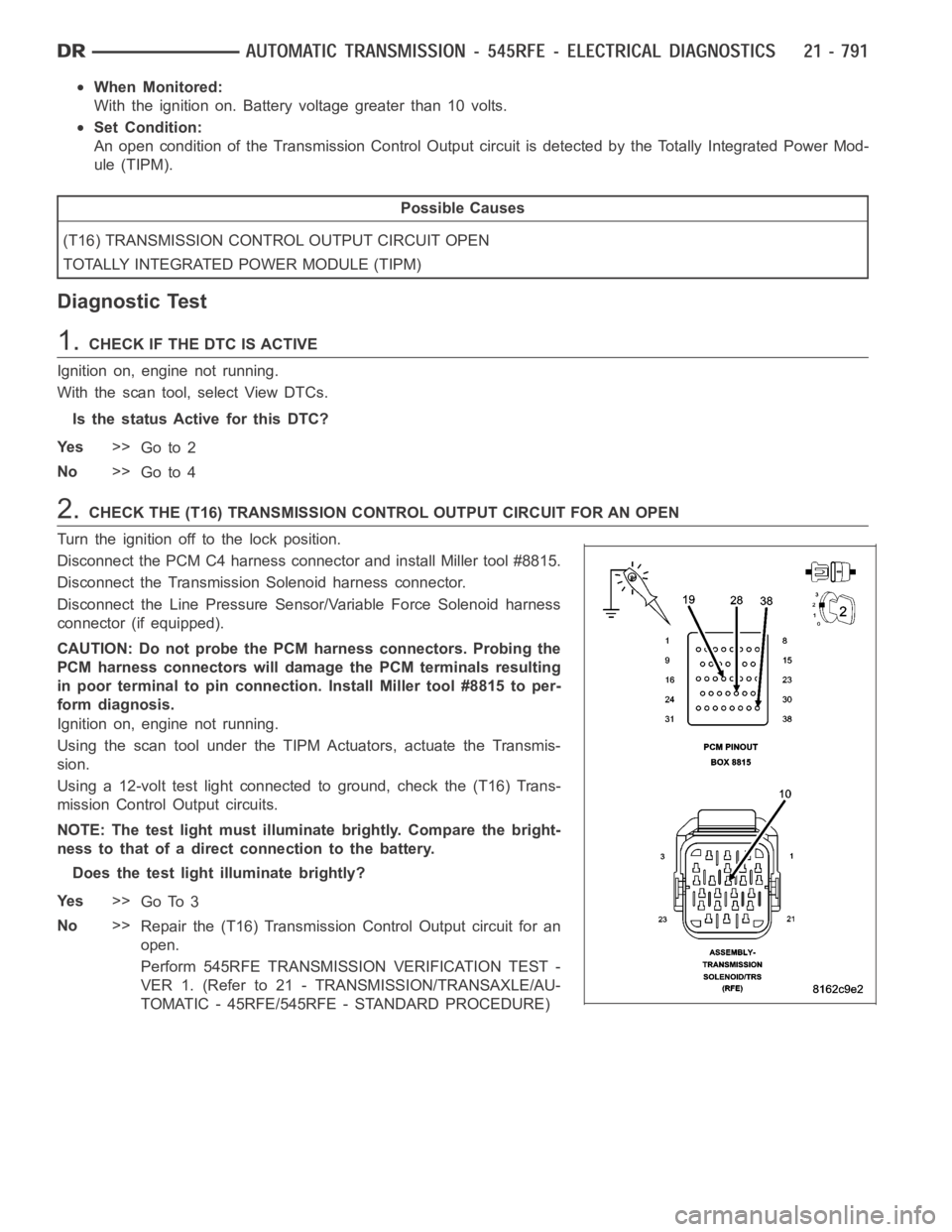
2.CHECK THE (T16) TRANSMISSION CONTROL OUTPUT CIRCUIT FOR AN OPEN
Turn the ignition off to the lock position.
Disconnect the PCM C4 harness connector and install Miller tool #8815.
Disconnect the Transmission Solenoid harness connector.
Disconnect the Line Pressure Sensor/Variable Force Solenoid harness
connector (if equipped).
CAUTION: Do not probe the PCM harness connectors. Probing the
PCM harness connectors will damage the PCM terminals resulting
in poor terminal to pin connection. Install Miller tool #8815 to per-
form diagnosis.
Ignition on, engine not running.
Using the scan tool under the TIPM Actuators, actuate the Transmis-
sion.
Using a 12-volt test light connected to ground, check the (T16) Trans-
mission Control Output circuits.
NOTE: The test light must illuminate brightly. Compare the bright-
ness to that of a direct connection to the battery.
Does the test light illuminate brightly?
Ye s>>
Go To 3
No>>
Repair the (T16) Transmission Control Output circuit for an
open.
Perform 545RFE TRANSMISSION VERIFICATION TEST -
VER 1. (Refer to 21 - TRANSMISSION/TRANSAXLE/AU-
TOMATIC - 45RFE/545RFE - STANDARD PROCEDURE)