2006 DODGE RAM SRT-10 light
[x] Cancel search: lightPage 3374 of 5267
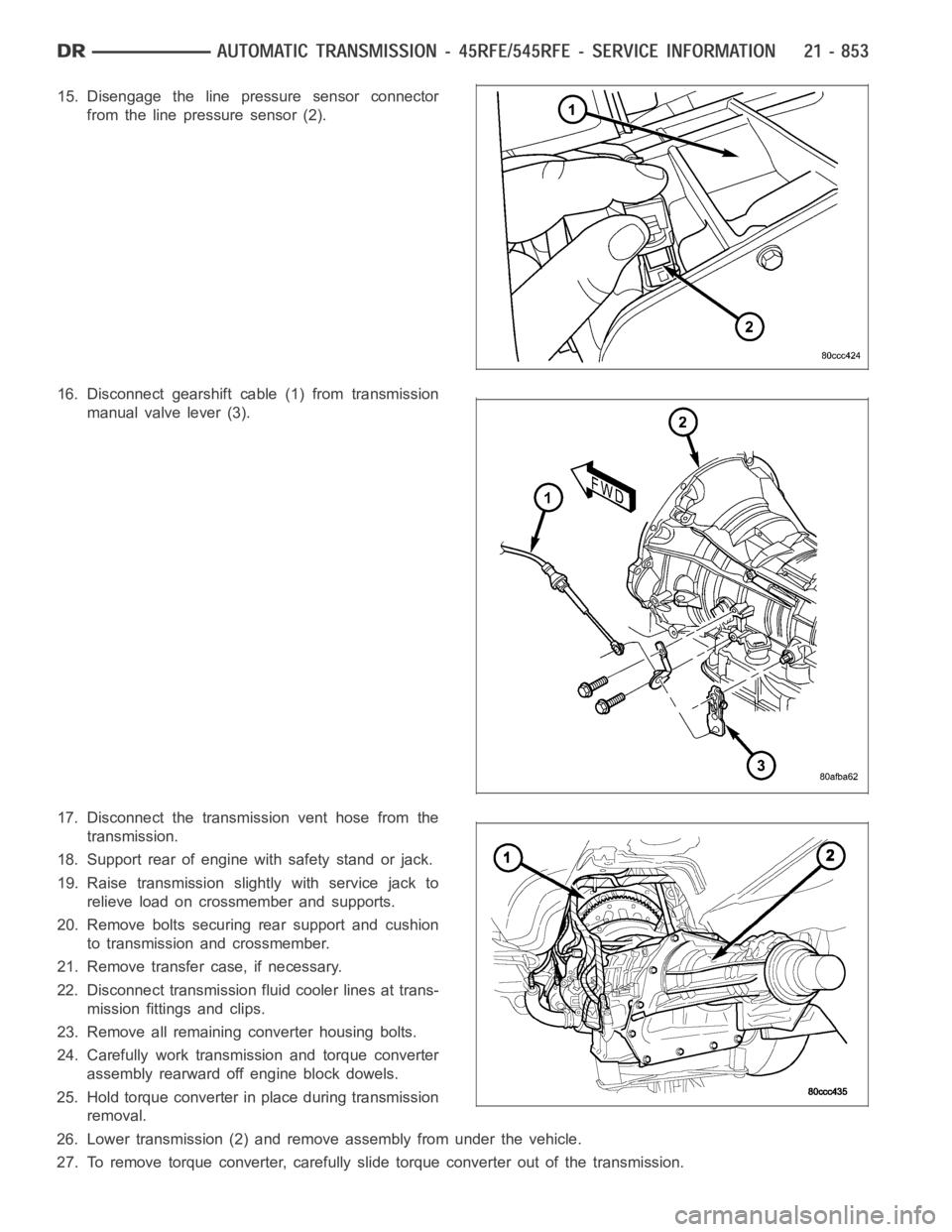
15. Disengage the line pressure sensor connector
from the line pressure sensor (2).
16. Disconnect gearshift cable (1) from transmission
manual valve lever (3).
17. Disconnect the transmission vent hose from the
transmission.
18. Support rear of engine with safety stand or jack.
19. Raise transmission slightly with service jack to
relieve load on crossmember and supports.
20. Remove bolts securing rear support and cushion
to transmission and crossmember.
21. Remove transfer case, if necessary.
22. Disconnect transmission fluid cooler lines at trans-
mission fittings and clips.
23. Remove all remaining converter housing bolts.
24. Carefully work transmission and torque converter
assembly rearward off engine block dowels.
25. Hold torque converter in place during transmission
removal.
26. Lower transmission (2) and remove assembly from under the vehicle.
27. To remove torque converter, carefully slide torque converter out of the transmission.
Page 3392 of 5267
INSTALLATION
1. Check torque converter hub and hub drive flats for
sharp edges burrs, scratches, or nicks. Polish the
hub and flats with 320/400 grit paper and crocus
cloth if necessary. Verify that the converter hub
o-ring is properly installed and is free of any debris.
The hub must be smooth to avoid damaging pump
seal at installation.
2. If a replacement transmission is being installed,
transfer any components necessary, such as the
manual shift lever and shift cable bracket, from the
original transmission onto the replacement trans-
mission.
3. Lubricate oil pump seal lip with transmission fluid.
4. Align converter and oil pump.
5. Carefully insert converter in oil pump. Then rotate
converter back and forth until fully seated in pump
gears.
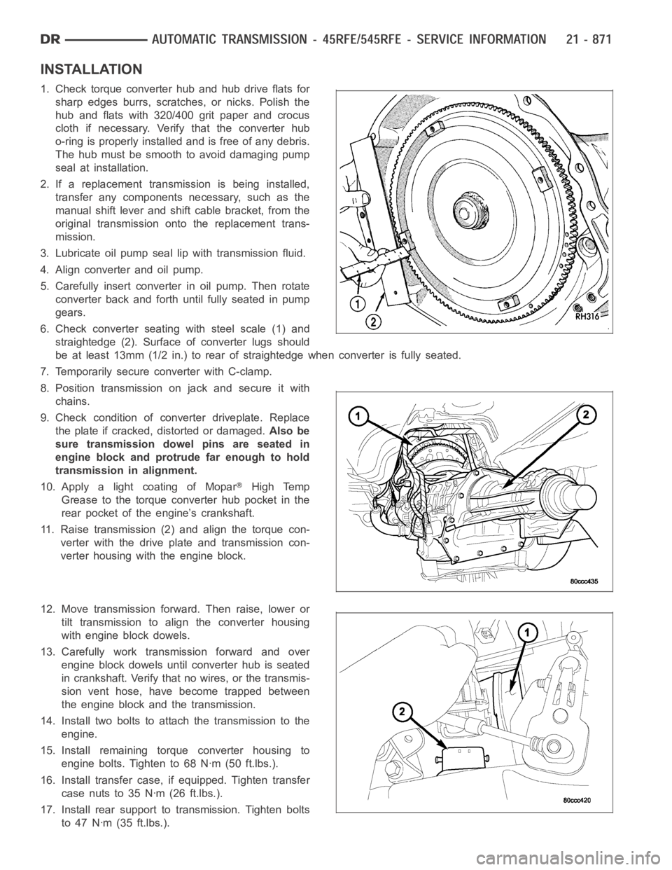
6. Check converter seating with steel scale (1) and
straightedge (2). Surface of converter lugs should
be at least 13mm (1/2 in.) to rear of straightedge when converter is fully seated.
7. Temporarily secure converter with C-clamp.
8. Position transmission on jack and secure it with
chains.
9. Check condition of converter driveplate. Replace
the plate if cracked, distorted or damaged.Also be
sure transmission dowel pins are seated in
engine block and protrude far enough to hold
transmission in alignment.
10. Apply a light coating of Mopar
High Temp
Grease to the torque converter hub pocket in the
rear pocket of the engine’s crankshaft.
11. Raise transmission (2) and align the torque con-
verter with the drive plate and transmission con-
verter housing with the engine block.
12. Move transmission forward. Then raise, lower or
tilt transmission to align the converter housing
with engine block dowels.
13. Carefully work transmission forward and over
engine block dowels until converter hub is seated
in crankshaft. Verify that no wires, or the transmis-
sion vent hose, have become trapped between
theengineblockandthetransmission.
14. Install two bolts to attach the transmission to the
engine.
15. Install remaining torque converter housing to
engine bolts. Tighten to 68 Nꞏm (50 ft.lbs.).
16. Install transfer case, if equipped. Tighten transfer
case nuts to 35 Nꞏm (26 ft.lbs.).
17. Install rear support to transmission. Tighten bolts
to 47 Nꞏm (35 ft.lbs.).
Page 3432 of 5267
FLUID AND FILTER REPLACEMENT
For proper service intervals (Refer to LUBRICATION & MAINTENANCE/MAINTENANCE SCHEDULES - DESCRIP-
TION).
REMOVAL
1. Hoist and support vehicle on safety stands.
2. Place a large diameter shallow drain pan beneath the transmission pan.
3. Remove bolts holding front and sides of pan to transmission.
4. Loosen bolts holding rear of pan to transmission.
5. Slowly separate front of pan away from transmission allowing the fluid to drain into drain pan.
6. Hold up pan and remove remaining bolts holding pan to transmission.
7. While holding pan level, lower pan away from transmission.
8. Pour remaining fluid in pan into drain pan.
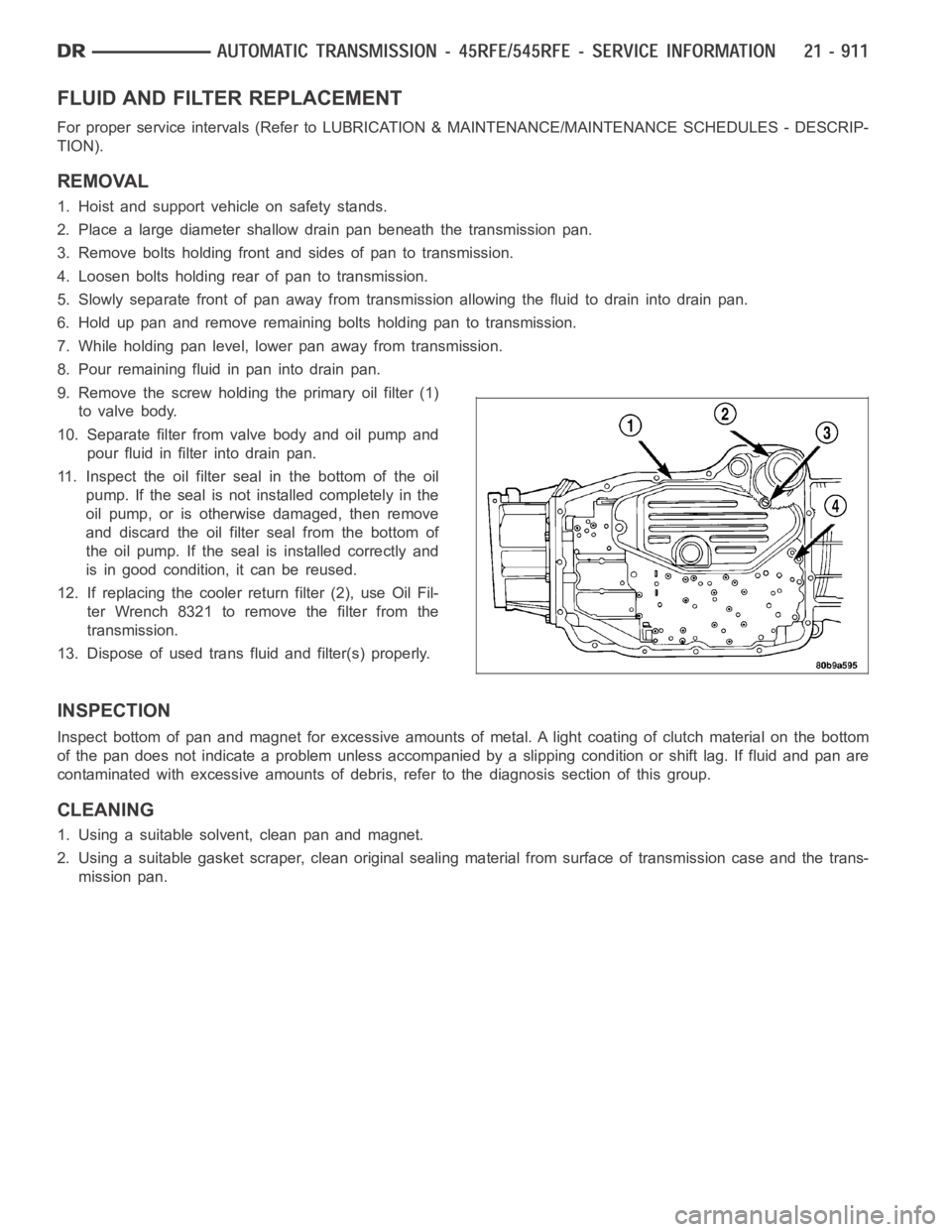
9. Remove the screw holding the primary oil filter (1)
to valve body.
10. Separate filter from valve body and oil pump and
pour fluid in filter into drain pan.
11. Inspect the oil filter seal in the bottom of the oil
pump. If the seal is not installed completely in the
oil pump, or is otherwise damaged, then remove
and discard the oil filter seal from the bottom of
the oil pump. If the seal is installed correctly and
is in good condition, it can be reused.
12. If replacing the cooler return filter (2), use Oil Fil-
ter Wrench 8321 to remove the filter from the
transmission.
13. Dispose of used trans fluid and filter(s) properly.
INSPECTION
Inspect bottom of pan and magnet for excessive amounts of metal. A light coating of clutch material on the bottom
of the pan does not indicate a problem unless accompanied by a slipping condition or shift lag. If fluid and pan are
contaminated with excessive amounts of debris, refer to the diagnosis section of this group.
CLEANING
1. Using a suitable solvent, clean pan and magnet.
2. Using a suitable gasket scraper, clean original sealing material from surface of transmission case and the trans-
mission pan.
Page 3467 of 5267
INSPECTION
Check condition of the seal rings and thrust washer on the reaction shaft support. The seal rings do not need to be
replaced unless cracked, broken, or severely worn.
Inspect the pump and support components. Replace the pump or support if theseal ring grooves or machined sur-
faces are worn, scored, pitted, or damaged. Replace the pump gears if pitted, worn chipped, or damaged.
Inspect the pump reaction shaft support bushings. Replace either bushingonly if heavily worn, scored or damaged.
It is not necessary to replace the bushings unless they are actually damaged.
Inspect the valves and plugs for scratches, burrs, nicks, or scores. Minorsurface scratches on steel valves and
plugs can be removed with crocus cloth butdo not round off the edges of the valve or plug lands.Maintaining
sharpness of these edges is vitally important. The edges prevent foreign matter from lodging between the valves
and plugs and the bore.
Inspect all the valve and plug bores in the oil pump cover. Use a penlight to view the bore interiors. Replace the oil
pump if any bores are distorted or scored. Inspect all of the valve springs.The springs must be free of distortion,
warpageorbrokencoils.
Trial fit each valve and plug in its bore to check freedom of operation. Whenclean and dry, the valves and plugs
shoulddropfreelyintothebores.
ASSEMBLY
NOTE: Clean and inspect all components. Make sure that all passages are thoroughly cleaned and are free
from dirt or debris. Make sure that all valves move freely in their proper bore. Make sure that all gear pock-
ets and bushings are free from excessive wear and scoring. Replace the oil pump if any excessive wear or
scoring is found.
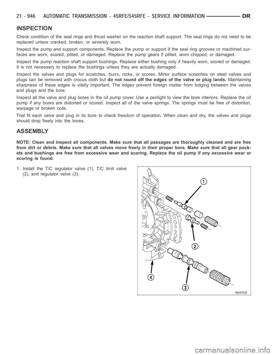
1. Install the T/C regulator valve (1), T/C limit valve
(2), and regulator valve (3).
Page 3474 of 5267
SWITCH-TOW/HAUL OVERDRIVE
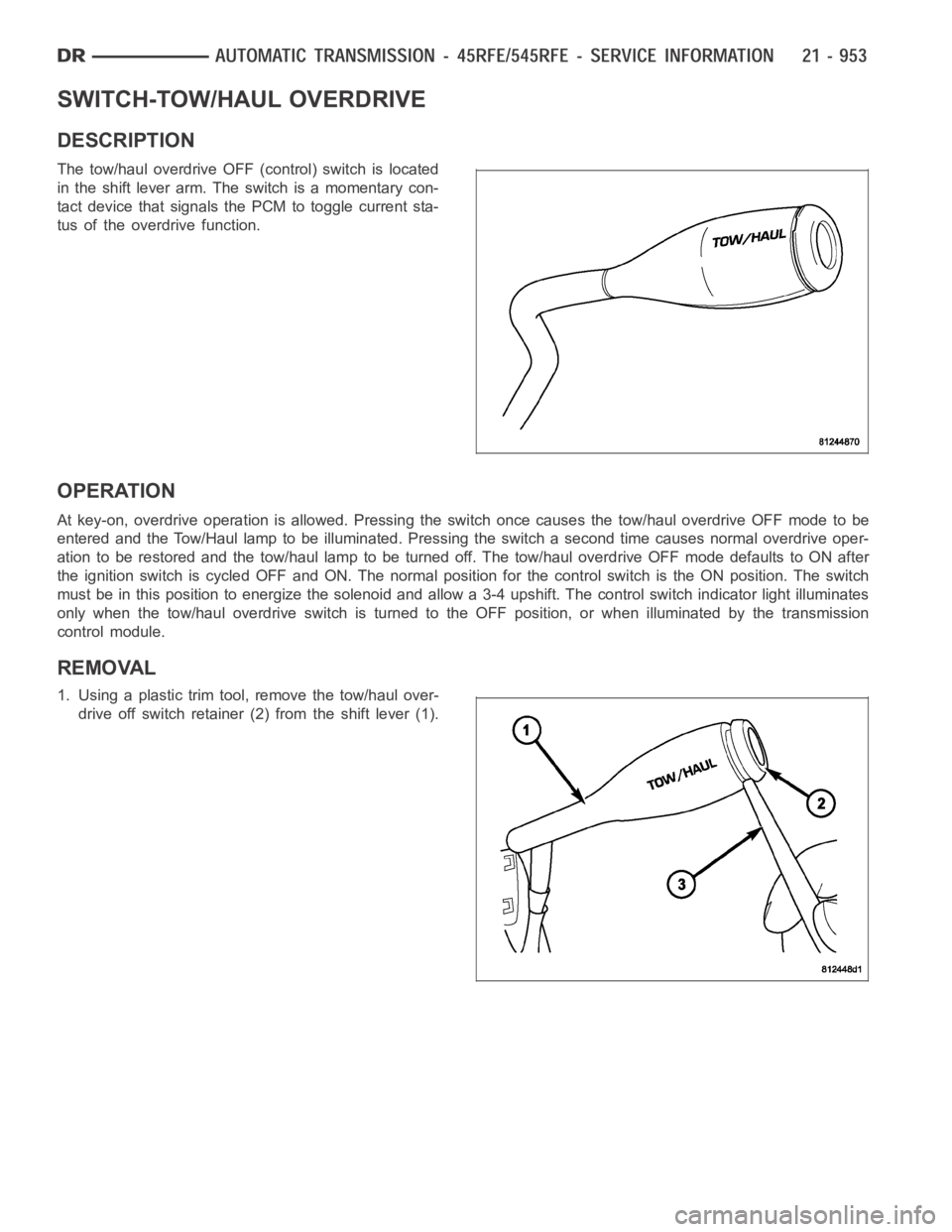
DESCRIPTION
The tow/haul overdrive OFF (control) switch is located
in the shift lever arm. The switch is a momentary con-
tact device that signals the PCM to toggle current sta-
tus of the overdrive function.
OPERATION
At key-on, overdrive operation is allowed. Pressing the switch once causes the tow/haul overdrive OFF mode to be
entered and the Tow/Haul lamp to be illuminated. Pressing the switch a second time causes normal overdrive oper-
ationtoberestoredandthetow/haullamptobeturnedoff.Thetow/hauloverdrive OFF mode defaults to ON after
the ignition switch is cycled OFF and ON. The normal position for the control switch is the ON position. The switch
must be in this position to energize the solenoid and allow a 3-4 upshift. The control switch indicator light illuminates
only when the tow/haul overdrive switch is turned to the OFF position, or when illuminated by the transmission
control module.
REMOVAL
1. Using a plastic trim tool, remove the tow/haul over-
drive off switch retainer (2) from the shift lever (1).
Page 3486 of 5267
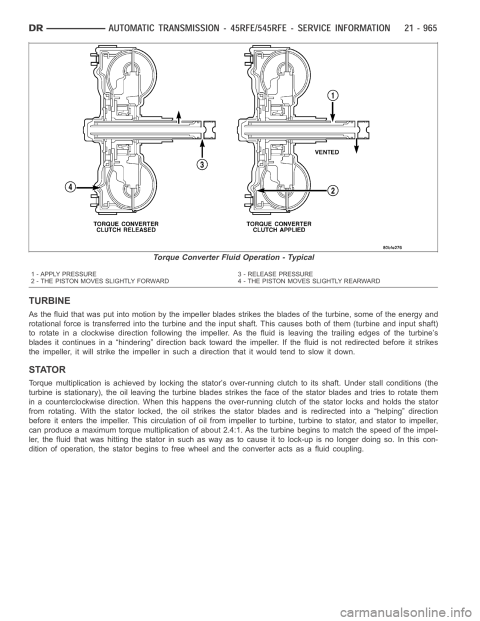
TURBINE
As the fluid that was put into motion bythe impeller blades strikes the blades of the turbine, some of the energy and
rotational force is transferred into the turbine and the input shaft. Thiscauses both of them (turbine and input shaft)
to rotate in a clockwise direction following the impeller. As the fluid is leaving the trailing edges of the turbine’s
blades it continues in a “hindering” direction back toward the impeller. If the fluid is not redirected before it strikes
the impeller, it will strike the impeller in such a direction that it would tend to slow it down.
STATOR
Torque multiplication is achieved by locking the stator’s over-running clutch to its shaft. Under stall conditions (the
turbine is stationary), the oil leaving the turbine blades strikes the face of the stator blades and tries to rotate them
in a counterclockwise direction. When this happens the over-running clutch of the stator locks and holds the stator
from rotating. With the stator locked, the oil strikes the stator blades and is redirected into a “helping” direction
before it enters the impeller. This circulation of oil from impeller to turbine, turbine to stator, and stator to impeller,
can produce a maximum torque multiplicationofabout2.4:1.Astheturbinebegins to match the speed of the impel-
ler, the fluid that was hitting the stator in such as way as to cause it to lock-up is no longer doing so. In this con-
dition of operation, the stator begins to free wheel and the converter actsas a fluid coupling.
Torque Converter Fluid Operation - Typical
1 - APPLY PRESSURE 3 - RELEASE PRESSURE
2 - THE PISTON MOVES SLIGHTLY FORWARD 4 - THE PISTON MOVES SLIGHTLY REARWARD
Page 3487 of 5267
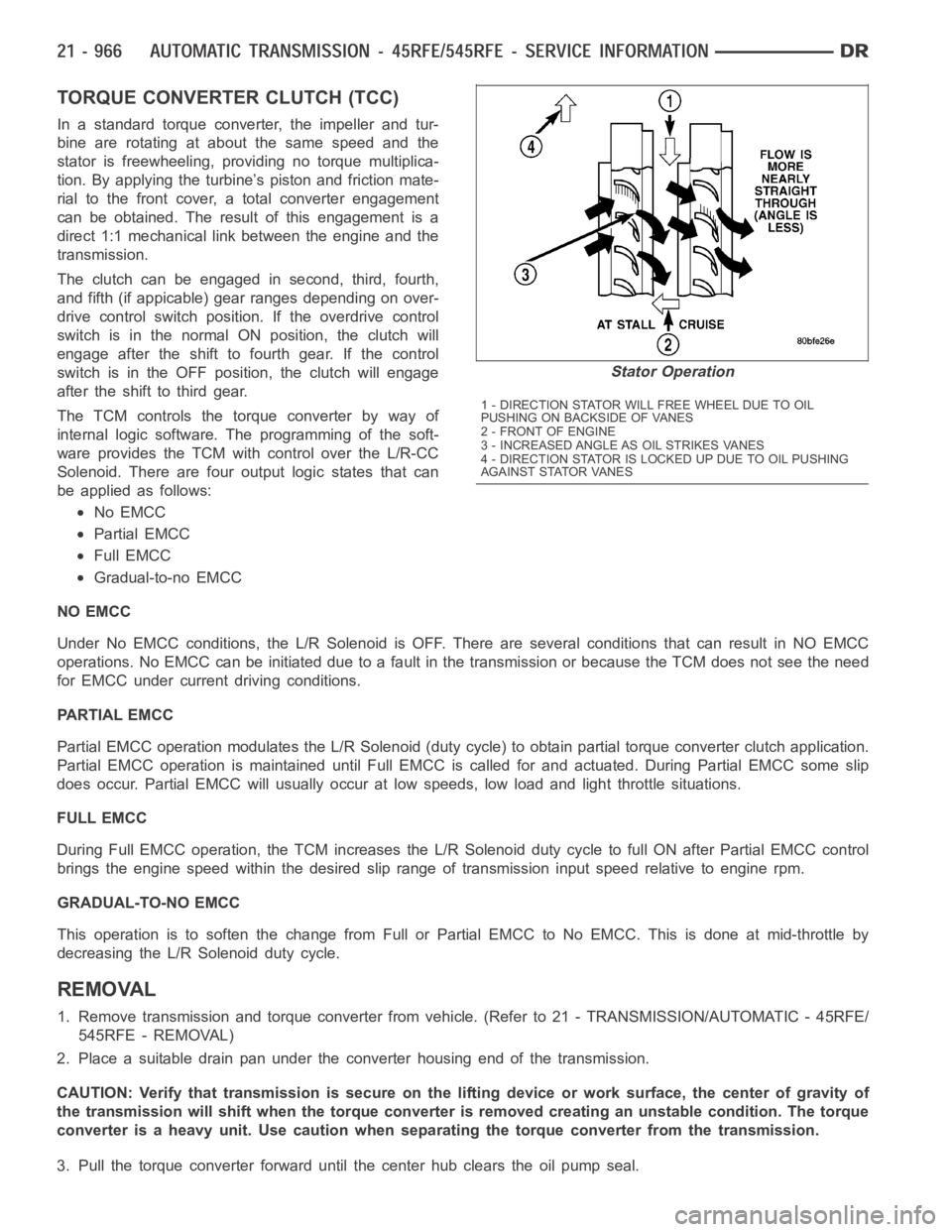
TORQUE CONVERTER CLUTCH (TCC)
In a standard torque converter, the impeller and tur-
bine are rotating at about the same speed and the
stator is freewheeling, providing no torque multiplica-
tion. By applying the turbine’s piston and friction mate-
rial to the front cover, a total converter engagement
can be obtained. The result of this engagement is a
direct 1:1 mechanical link between the engine and the
transmission.
The clutch can be engaged in second, third, fourth,
and fifth (if appicable) gear ranges depending on over-
drive control switch position. If the overdrive control
switch is in the normal ON position, the clutch will
engage after the shift to fourth gear. If the control
switch is in the OFF position, the clutch will engage
after the shift to third gear.
The TCM controls the torque converter by way of
internal logic software. The programming of the soft-
ware provides the TCM with control over the L/R-CC
Solenoid. There are four output logic states that can
be applied as follows:
No EMCC
Partial EMCC
Full EMCC
Gradual-to-no EMCC
NO EMCC
Under No EMCC conditions, the L/R Solenoid is OFF. There are several conditions that can result in NO EMCC
operations. No EMCC can be initiated due to a fault in the transmission or because the TCM does not see the need
for EMCC under current driving conditions.
PARTIAL EMCC
Partial EMCC operation modulates the L/R Solenoid (duty cycle) to obtain partial torque converter clutch application.
Partial EMCC operation is maintaineduntil Full EMCC is called for and actuated. During Partial EMCC some slip
does occur. Partial EMCC will usually occur at low speeds, low load and light throttle situations.
FULL EMCC
During Full EMCC operation, the TCM increases the L/R Solenoid duty cycle to full ON after Partial EMCC control
brings the engine speed within the desired slip range of transmission input speed relative to engine rpm.
GRADUAL-TO-NO EMCC
This operation is to soften the change from Full or Partial EMCC to No EMCC. This is done at mid-throttle by
decreasing the L/R Solenoid duty cycle.
REMOVAL
1. Remove transmission and torque converter from vehicle. (Refer to 21 - TRANSMISSION/AUTOMATIC - 45RFE/
545RFE - REMOVAL)
2. Place a suitable drain pan under the converter housing end of the transmission.
CAUTION: Verify that transmission is secure on the lifting device or work surface, the center of gravity of
the transmission will shift when the torque converter is removed creatingan unstable condition. The torque
converter is a heavy unit. Use caution when separating the torque converter from the transmission.
3. Pull the torque converter forward until the center hub clears the oil pumpseal.
Stator Operation
1 - DIRECTION STATOR WILL FREE WHEEL DUE TO OIL
PUSHING ON BACKSIDE OF VANES
2-FRONTOFENGINE
3 - INCREASED ANGLE AS OIL STRIKES VANES
4 - DIRECTION STATOR IS LOCKED UP DUE TO OIL PUSHING
AGAINST STATOR VANES
Page 3502 of 5267
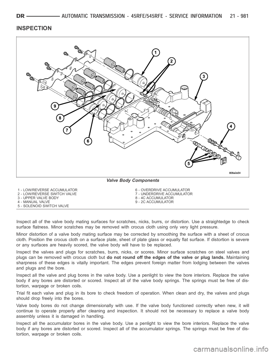
INSPECTION
Inspect all of the valve body mating surfaces for scratches, nicks, burrs,or distortion. Use a straightedge to check
surface flatness. Minor scratches may be removed with crocus cloth using only very light pressure.
Minor distortion of a valve body mating surface may be corrected by smoothing the surface with a sheet of crocus
cloth. Position the crocus cloth on a surface plate, sheet of plate glass orequally flat surface. If distortion is severe
or any surfaces are heavily scored, the valve body will have to be replaced.
Inspect the valves and plugs for scratches, burrs, nicks, or scores. Minorsurface scratches on steel valves and
plugs can be removed with crocus cloth butdo not round off the edges of the valve or plug lands.Maintaining
sharpness of these edges is vitally important. The edges prevent foreign matter from lodging between the valves
and plugs and the bore.
Inspect all the valve and plug bores in the valve body. Use a penlight to viewthe bore interiors. Replace the valve
body if any bores are distorted or scored. Inspect all of the valve body springs. The springs must be free of dis-
tortion, warpage or broken coils.
Trial fit each valve and plug in its bore to check freedom of operation. Whenclean and dry, the valves and plugs
shoulddropfreelyintothebores.
Valve body bores do not change dimensionally with use. If the valve body functioned correctly when new, it will
continue to operate properly after cleaning and inspection. It should notbe necessary to replace a valve body
assembly unless it is damaged in handling.
Inspect all the accumulator bores in the valve body. Use a penlight to view the bore interiors. Replace the valve
body if any bores are distorted or scored. Inspect all of the accumulator springs. The springs must be free of dis-
tortion, warpage or broken coils.
Valve Body Components
1 - LOW/REVERSE ACCUMULATOR 6 - OVERDRIVE ACCUMULATOR
2 - LOW/REVERSE SWITCH VALVE 7 - UNDERDRIVE ACCUMULATOR
3 - UPPER VALVE BODY 8 - 4C ACCUMULATOR
4 - MANUAL VALVE 9 - 2C ACCUMULATOR
5 - SOLENOID SWITCH VALVE