2006 DODGE RAM SRT-10 oil pressure
[x] Cancel search: oil pressurePage 2078 of 5267
COVER-TIMING CHAIN
REMOVAL
1. Disconnect negative battery cable.
2. Disconnect throttle body air inlet duct at the throttle
body, CCV hose, disconnect the IAT sensor and
remove air cleaner housing cover (Refer to 9 -
ENGINE/AIR INTAKE SYSTEM - REMOVAL).
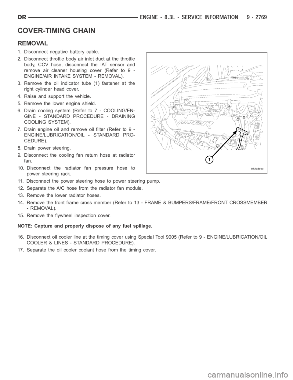
3. Remove the oil indicator tube (1) fastener at the
right cylinder head cover.
4. Raise and support the vehicle.
5. Remove the lower engine shield.
6. Drain cooling system (Refer to 7 - COOLING/EN-
GINE - STANDARD PROCEDURE - DRAINING
COOLING SYSTEM).
7. Drain engine oil and remove oil filter (Refer to 9 -
ENGINE/LUBRICATION/OIL - STANDARD PRO-
CEDURE).
8. Drain power steering.
9. Disconnect the cooling fan return hose at radiator
fan.
10. Disconnect the radiator fan pressure hose to
power steering rack.
11. Disconnect the power steering hose to power steering pump.
12. Separate the A/C hose from the radiator fan module.
13. Remove the lower radiator hoses.
14. Remove the front frame cross member (Refer to 13 - FRAME & BUMPERS/FRAME/FRONT CROSSMEMBER
- REMOVAL).
15. Remove the flywheel inspection cover.
NOTE: Capture and properly dispose of any fuel spillage.
16. Disconnect oil cooler line at the timing cover using Special Tool 9005 (Refer to 9 - ENGINE/LUBRICATION/OIL
COOLER & LINES - STANDARD PROCEDURE).
17. Separate the oil cooler coolant hose from the timing cover.
Page 2086 of 5267
LUBRICATION
DESCRIPTION
The engine lubrication system is a full-flow filtration pressure feed type.
OPERATION
Engine oil stored in the oil pan is taken in and discharged by an internal geartypeoilpump,whichisdrivenbythe
crankshaft. A pressure relief valve is located in the timing chain case cover; it regulates oil pressure. The oil is
pumped through an oil filter and feeds a main oil gallery. Also, oil is routedtoanexternaloilcooler.Themainoil
gallery feeds oil under pressure to the main bearings, connecting rod bearings, and camshaft bearings. Passages in
the cylinder block feed oil to the hydraulic lifters. The oil then flows through hollow pushrods, which feed the rocker
arm pivots.
DIAGNOSIS AND TESTING
CHECKING ENGINE OIL PRESSURE
1. Remove oil pressure sensor (Refer to 9 - ENGINE/LUBRICATION/OIL PRESSURE SENSOR - REMOVAL).
2. Install oil pressure gauge.
3. Warm engine at high idle until thermostat opens.
CAUTION: If oil pressure is 0 at idle, Do Not Run engine at 3000 RPM.
4. Oil pressure should be 68.9 kPa (10 psi) at idle or 310 - 517 kPa (45 - 75 psi)at 3000 RPM.
5. If oil pressure is 0 at idle, shut off engine. Check for a clogged oil pick-up screen or a pressure relief valve stuck
open.
ENGINE OIL LEAK
Begin with a thorough visual inspection of the engine, particularly at thearea of the suspected leak. If an oil leak
source is not readily identifiable, thefollowingstepsshouldbefollowed:
1. Do not clean or degrease the engine at this time because some solvents maycause rubber to swell, temporarily
stopping the leak.
2. Add an oil soluble dye (use as recommended by manufacturer). Start the engine and let idle for approximately 15
minutes. Check the oil dipstick to make sure the dye is thoroughly mixed as indicated with a bright yellow color
under a black light.
3. Using a black light, inspect the entire engine for fluorescent dye, particularly at the suspected area of oil leak. If
the oil leak is found and identified, repair per service manual instructions.
4. If dye is not observed, drive the vehicle at various speeds for approximately 24 km (15 miles), and repeat inspec-
tion.If the oil leak source is not positively identified at this time, proceed with the air leak detection test
method.
Air Leak Detection Test Method
1. Remove the PCV valve from the IAFM. Cap or plug the PCV valve grommet.
2. Attach an air hose with pressure gauge and regulator to the dipstick tube.
CAUTION: Do not subject the engine assembly to more than 20.6 kPa (3 PSI) of test pressure.
3. Gradually apply air pressure from 6.89 - 17.23 kPa (1 - 2.5 psi) maximum while applying soapy water at the
suspected source. Adjust the regulator to the suitable test pressure thatprovide the best bubbles which will pin-
point the leak source. If the oil leak is detected and identified, repair per service manual procedures.
4. If the leakage occurs at the rear oil seal area, refer to the section, Inspection for Rear Seal Area Leak.
5. If no leaks are detected, turn off the air supply and remove the air hose and all plugs and caps. Install the PCV
valve.
6. Clean the oil off the suspect oil leak area using a suitable solvent. Drive the vehicle at various speeds approx-
imately 24 km (15 miles). Inspect the engine for signs of an oil leak by usinga black light.
Page 2098 of 5267
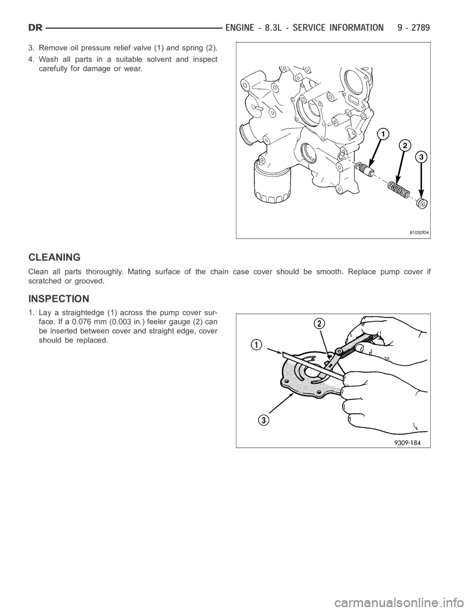
3. Remove oil pressure relief valve (1) and spring (2).
4. Wash all parts in a suitable solvent and inspect
carefully for damage or wear.
CLEANING
Clean all parts thoroughly. Mating surface of the chain case cover should be smooth. Replace pump cover if
scratched or grooved.
INSPECTION
1. Lay a straightedge (1) across the pump cover sur-
face. If a 0.076 mm (0.003 in.) feeler gauge (2) can
be inserted between cover and straight edge, cover
should be replaced.
Page 2100 of 5267
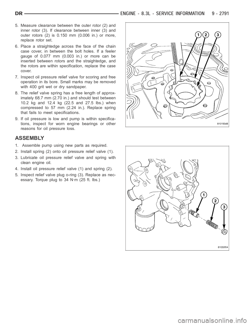
5. Measure clearance between the outer rotor (2) and
inner rotor (3). If clearance between inner (3) and
outer rotors (2) is 0.150 mm (0.006 in.) or more,
replace rotor set.
6. Place a straightedge across the face of the chain
case cover, in between the bolt holes. If a feeler
gauge of 0.077 mm (0.003 in.) or more can be
inserted between rotors and the straightedge, and
the rotors are within specification, replace the case
cover.
7. Inspect oil pressure relief valve for scoring and free
operation in its bore. Small marks may be removed
with 400 grit wet or dry sandpaper.
8. The relief valve spring has a free length of approx-
imately 68.7 mm (2.70 in.) and should test between
10.2 kg and 12.4 kg (22.5 and 27.5 lbs.) when
compressedto57mm(2.24in.). Replace spring
that fails to meet specifications.
9. If oil pressure is low and pump is within specifica-
tions, inspect for worn engine bearings or other
reasons for oil pressure loss.
ASSEMBLY
1. Assemble pump using new parts as required.
2. Install spring (2) onto oil pressure relief valve (1).
3. Lubricate oil pressure relief valve and spring with
clean engine oil.
4. Install oil pressure relief valve (1) and spring (2).
5. Inspect relief valve plug o-ring (3). Replace as nec-
essary. Torque plug to 34 Nꞏm (25 ft. lbs.)
Page 2102 of 5267

SENSOR-OIL PRESSURE
REMOVAL
1. Disconnect oil pressure sensor electrical connector.
2. Remove oil pressure sensor (1).
INSTALLATION
1. Apply thread sealer to oil pressure sensor threads.
2. Install oil pressure sensor (1).
3. Connect electrical connector.
Page 2108 of 5267
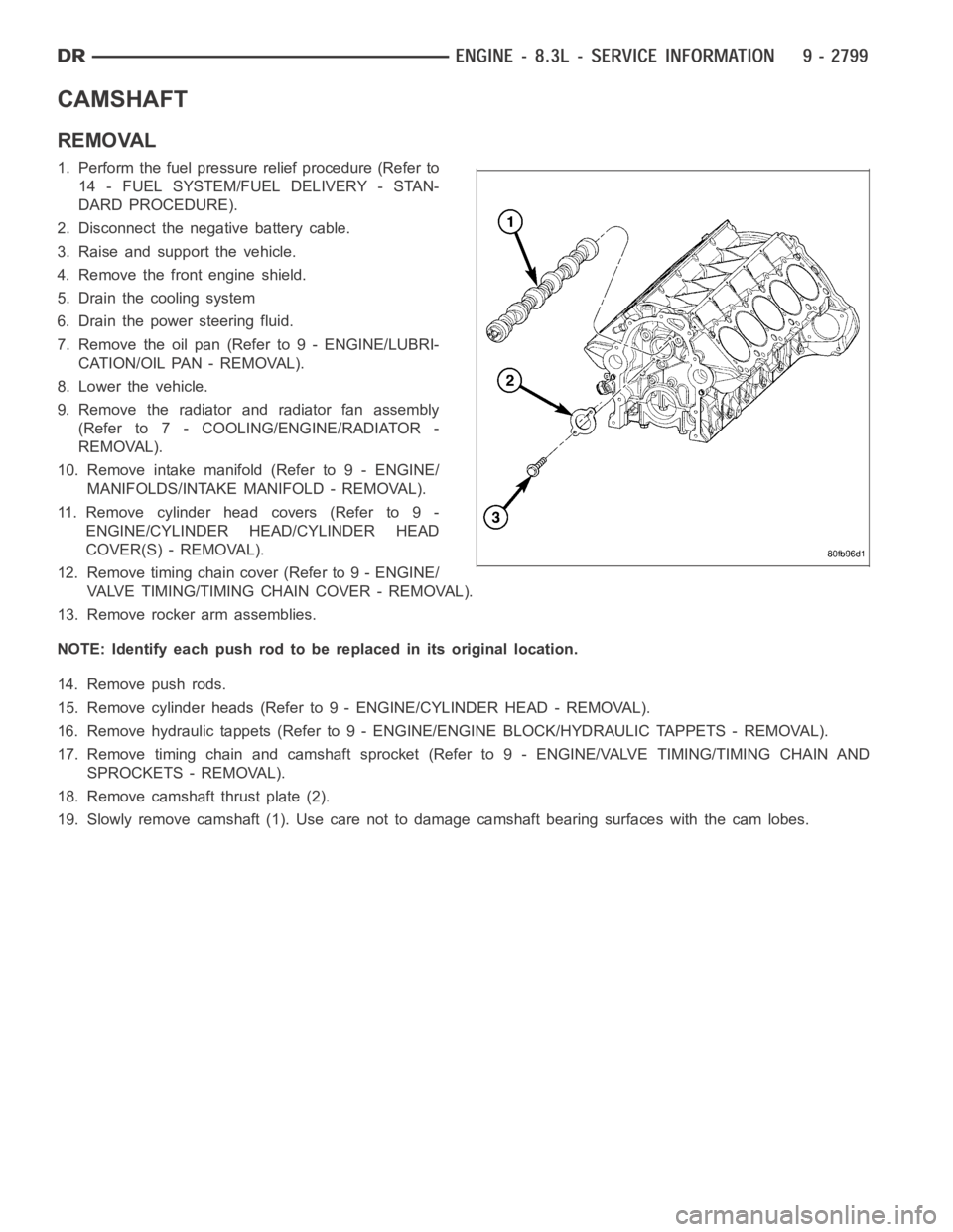
CAMSHAFT
REMOVAL
1. Perform the fuel pressure relief procedure (Refer to
14 - FUEL SYSTEM/FUEL DELIVERY - STAN-
DARD PROCEDURE).
2. Disconnect the negative battery cable.
3. Raise and support the vehicle.
4. Remove the front engine shield.
5. Drain the cooling system
6. Drain the power steering fluid.
7. Remove the oil pan (Refer to 9 - ENGINE/LUBRI-
CATION/OIL PAN - REMOVAL).
8. Lower the vehicle.
9. Remove the radiator and radiator fan assembly
(Refer to 7 - COOLING/ENGINE/RADIATOR -
REMOVAL).
10. Remove intake manifold (Refer to 9 - ENGINE/
MANIFOLDS/INTAKE MANIFOLD - REMOVAL).
11. Remove cylinder head covers (Refer to 9 -
ENGINE/CYLINDER HEAD/CYLINDER HEAD
COVER(S) - REMOVAL).
12. Remove timing chain cover (Refer to 9 - ENGINE/
VALVE TIMING/TIMING CHAIN COVER - REMOVAL).
13. Remove rocker arm assemblies.
NOTE: Identify each push rod to be replaced in its original location.
14. Remove push rods.
15. Remove cylinder heads (Refer to 9 - ENGINE/CYLINDER HEAD - REMOVAL).
16. Remove hydraulic tappets (Refer to 9 - ENGINE/ENGINE BLOCK/HYDRAULICTAPPETS - REMOVAL).
17. Remove timing chain and camshaft sprocket (Refer to 9 - ENGINE/VALVE TIMING/TIMING CHAIN AND
SPROCKETS - REMOVAL).
18. Remove camshaft thrust plate (2).
19. Slowly remove camshaft (1). Use care not to damage camshaft bearing surfaces with the cam lobes.
Page 2136 of 5267
EXHAUST SYSTEM
TABLE OF CONTENTS
page page
EXHAUST SYSTEM
DESCRIPTION
GAS ENGINES ............................... 2
5.9L DIESEL ................................. 3
DIAGNOSIS AND TESTING
GAS ENGINE ................................ 4
DIESEL ENGINE............................. 5
SPECIFICATIONS
TORQUE .................................... 5
SPECIAL TOOLS ............................... 7
CONVERTER-CATALYTIC
DESCRIPTION ................................. 8
OPERATION ................................... 8
REMOVAL
3.7L/4.7L ENGINE ............................ 8
5.7L ENGINE ................................ 9
5.9L DIESEL ENGINE ......................... 9
8.3L ENGINE ............................... 10
INSPECTION ................................. 10
INSTALLATION
3.7L/4.7L ENGINE ........................... 10
5.7L ENGINE ............................... 11
5.9L ENGINE DIESEL ........................ 11
8.3L ENGINE ............................... 12
PIPE EXHAUST
REMOVAL
3.7L/4.7L/5.7L ENGINE ...................... 13
5.9L DIESEL ................................ 13
8.3L ENGINE ............................... 13
INSPECTION ................................. 14
INSTALLATION
3.7L/4.7L/5.7L ENGINE ...................... 14
5.9L DIESEL ................................ 14
8.3L ENGINE ............................... 15
HEAT SHIELDS
DESCRIPTION ................................ 16
REMOVAL .................................... 16
INSTALLATION ............................... 17
MUFFLER
REMOVAL
3.7L/4.7L/5.7L ENGINE ...................... 19
8.3L ENGINE ............................... 195.9L DIESEL ENGINE....................... 20
INSTALLATION
3.7L/4.7L/5.7L ENGINE ...................... 20
8.3L ENGINE ............................... 21
5.9L DIESEL ENGINE....................... 21
TAILPIPE
REMOVAL
3.7L/4.7L/5.7L ENGINE ...................... 22
5.9L DIESEL................................ 22
8.3L ENGINE ............................... 23
INSPECTION ................................. 23
INSTALLATION
3.7L/4.7L/5.7L ENGINE ...................... 23
5.9L DIESEL................................ 24
8.3L ENGINE ............................... 24
TURBOCHARGER SYSTEM
DIAGNOSIS AND TESTING
TURBOCHARGER BOOST PRESSURE ....... 25
TURBOCHARGER
DESCRIPTION ................................ 26
OPERATION .................................. 27
REMOVAL
TURBOCHARGER .......................... 29
TURBOCHARGER OIL DRAIN TUBE .......... 30
CLEANING ................................... 30
INSPECTION ................................. 30
INSTALLATION
TURBOCHARGER .......................... 31
TURBOCHARGER OIL DRAIN TUBE .......... 32
WASTEGATE - ELECTRONIC ACTUATOR
REMOVAL .................................... 33
INSTALLATION ............................... 33
CHARGE AIR COOLER AND PLUMBING
DESCRIPTION ................................ 34
OPERATION .................................. 34
DIAGNOSIS AND TESTING
CHARGE AIR COOLER SYSTEM - LEAKS.... 35
REMOVAL .................................... 35
CLEANING ................................... 36
INSPECTION ................................. 36
INSTALLATION ............................... 36
Page 2160 of 5267
TURBOCHARGER SYSTEM
DIAGNOSIS AND TESTING
TURBOCHARGER BOOST PRESSURE
Low turbocharger boost pressure can cause poor engine performance and driveability concerns. The following pro-
cedure will test the turbocharger boost pressure.
Causes of low boost pressure include the following:
Restricted air inlet system
Leak in charge air cooler system
Restricted/high pressure drop across charge air cooler
Damaged turbocharger compressor wheel housing
Turbocharger wastegate stuck open
Excessive exhaust restriction
Causes of excessively high boost pressure include:
Turbocharger wastegate stuck closed
Turbocharger wastegate signal line leaking or damaged
Damaged wastegate command valve O-rings
Wastegate command valve mechanically stuck in actuated position
Several Diagnostic Trouble Codes (DTCs) can be set that will indicate highor low system boost levels. There is a
DTC for circuit faults relating to the electronically controlled wastegate command valve.
(Refer to 11 - EXHAUST SYSTEM/TURBOCHARGER SYSTEM/CHARGE AIR COOLER AND PLUMBING - DIAG-
NOSIS AND TESTING) for diagnosing of low or high boost pressure due to leaks.
NOTE: If oil is present on either the inlet or exhaust side of the turbo charger, check the charge air cooler
for evidence of oil. Clean charge air cooler of any oil before starting the engine. Failure to do this can result
in severe engine damage.