2006 DODGE RAM SRT-10 oil pressure
[x] Cancel search: oil pressurePage 2492 of 5267
HOSES - LINK/COIL
REMOVAL
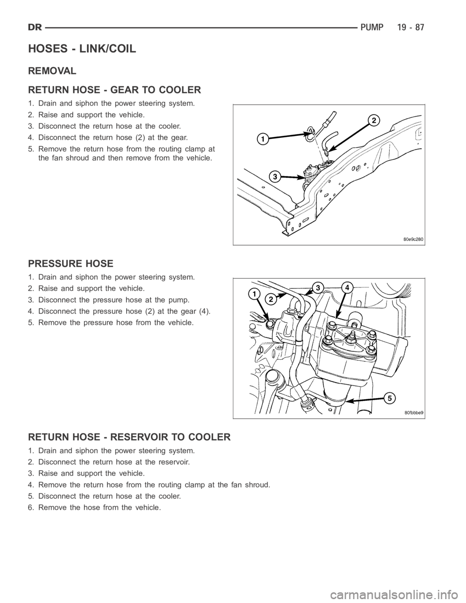
RETURN HOSE - GEAR TO COOLER
1. Drain and siphon the power steering system.
2. Raise and support the vehicle.
3. Disconnect the return hose at the cooler.
4. Disconnect the return hose (2) at the gear.
5. Remove the return hose from the routing clamp at
the fan shroud and then remove from the vehicle.
PRESSURE HOSE
1. Drain and siphon the power steering system.
2. Raise and support the vehicle.
3. Disconnect the pressure hose at the pump.
4. Disconnect the pressure hose (2) at the gear (4).
5. Remove the pressure hose from the vehicle.
RETURN HOSE - RESERVOIR TO COOLER
1. Drain and siphon the power steering system.
2. Disconnect the return hose at the reservoir.
3. Raise and support the vehicle.
4. Remove the return hose from the routing clamp at the fan shroud.
5. Disconnect the return hose at the cooler.
6. Remove the hose from the vehicle.
Page 2502 of 5267
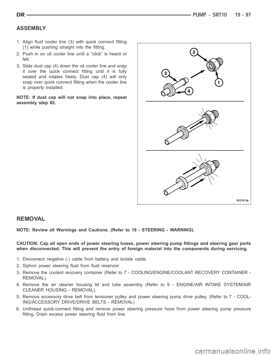
ASSEMBLY
1. Align fluid cooler line (3) with quick connect fitting
(1) while pushing straight into the fitting.
2. Push in on oil cooler line until a “click” is heard or
felt.
3. Slide dust cap (4) down the oil cooler line and snap
it over the quick connect fitting until it is fully
seated and rotates freely. Dust cap (4) will only
snap over quick connect fitting when the cooler line
is properly installed.
NOTE: If dust cap will not snap into place, repeat
assembly step #2.
REMOVAL
NOTE: Review all Warnings and Cautions. (Refer to 19 - STEERING - WARNING).
CAUTION: Cap all open ends of power steering hoses, power steering pump fittings and steering gear ports
when disconnected. This will prevent the entry of foreign material into the components during servicing.
1. Disconnect negative (-) cable from battery and isolate cable.
2. Siphon power steering fluid from fluid reservoir.
3. Remove the coolant recovery container (Refer to 7 - COOLING/ENGINE/COOLANT RECOVERY CONTAINER -
REMOVAL).
4. Remove the air cleaner housing lid and tube assembly (Refer to 9 - ENGINE/AIR INTAKE SYSTEM/AIR
CLEANER HOUSING - REMOVAL).
5. Remove accessory drive belt from tensioner pulley and power steering pump drive pulley. (Refer to 7 - COOL-
ING/ACCESSORY DRIVE/DRIVE BELTS - REMOVAL)
6. Unthread quick-connect fitting and remove power steering pressure hose from power steering pump pressure
fitting. Drain excess power steering fluid from line.
Page 2504 of 5267
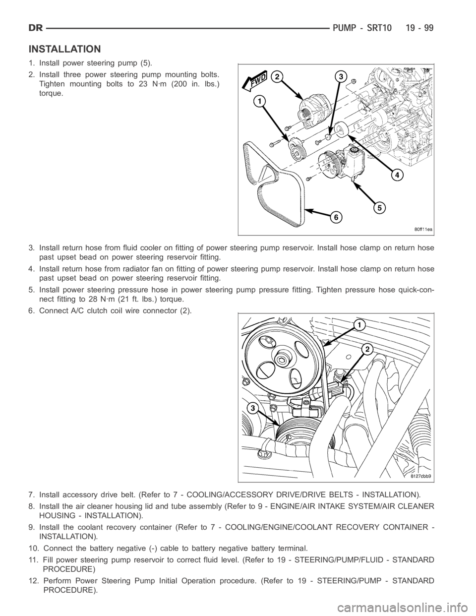
INSTALLATION
1. Install power steering pump (5).
2. Install three power steering pump mounting bolts.
Tighten mounting bolts to 23 Nꞏm (200 in. lbs.)
torque.
3. Install return hose from fluid cooler on fitting of power steering pump reservoir. Install hose clamp on return hose
past upset bead on power steering reservoir fitting.
4. Install return hose from radiator fan on fitting of power steering pump reservoir. Install hose clamp on return hose
past upset bead on power steering reservoir fitting.
5. Install power steering pressure hose in power steering pump pressure fitting. Tighten pressure hose quick-con-
nect fitting to 28 Nꞏm (21 ft. lbs.) torque.
6. Connect A/C clutch coil wire connector (2).
7. Install accessory drive belt. (Refer to 7 - COOLING/ACCESSORY DRIVE/DRIVE BELTS - INSTALLATION).
8. Install the air cleaner housing lid and tube assembly (Refer to 9 - ENGINE/AIR INTAKE SYSTEM/AIR CLEANER
HOUSING - INSTALLATION).
9. Install the coolant recovery container (Refer to 7 - COOLING/ENGINE/COOLANT RECOVERY CONTAINER -
INSTALLATION).
10. Connect the battery negative (-) cable to battery negative battery terminal.
11. Fill power steering pump reservoir to correct fluid level. (Refer to 19- STEERING/PUMP/FLUID - STANDARD
PROCEDURE)
12. Perform Power Steering Pump Initial Operation procedure. (Refer to 19- STEERING/PUMP - STANDARD
PROCEDURE).
Page 2523 of 5267
MANUAL TRANSMISSION - G56 - SERVICE INFORMATION
DIAGNOSIS AND TESTING
MANUAL TRANSMISSION - G56
LOW LUBRICANT LEVEL
A low transmission lubricant level is generally the result of a leak, inadequate lubricant fill or incorrect lubricant level
check.
Rear transmission leakswill be from the oil seals or component mating surfaces.
Front transmission leakswill be from the front input shaft retainer seal. Lubricant may drip from theclutchhousing
after extended operation. If leak is severe, it may contaminate the clutchdisc.
Lubricant level checkcan only be made when the vehicle is level and allowing the lubricant to settle for a minute
before checking. This will ensure an accurate check and avoid an under or overfill condition.
HARD SHIFTING
Hard shifting is usually caused by low lubricant level, improper or contaminated lubricants. This will cause noise,
excessive wear, internal bind, and hard shifting. Substantial lubricantleaks can result in gear, shift rail, synchro, and
bearing damage. The first indications of component damage is usually hardshifting and noise.
Shift component damage, clutch adjustment, worn pressure plate or disc are also causes of increased shift effort. If
clutch problem is advanced, gear clash during shifts can result. Worn or damaged synchronizer rings can cause
gear clash when shifting into any forward gear. In some new or rebuilt transmissions, new synchro rings may tend
to stick slightly causing hard or noisy shifts. In most cases, this condition will decline as the rings wear-in.
TRANSMISSION NOISE
Most manual transmissions make some noise during normal operation. Rotating gears generate a mild whine that is
audible, but generally only at extreme speeds.
Severe, highly audible transmission noise is generally the initial indicator of a lubricant problem. Insufficient,
improper or contaminated lubricant will promote rapid wear of gears, synchronizer rings, shift rails, forks and bear-
ings. The overheating caused by a lubricant problem, can also lead to gear and bearing damage.
Page 2592 of 5267
MANUAL TRANSMISSION - GETRAG 238 - SERVICE INFORMATION
DIAGNOSIS AND TESTING
MANUAL TRANSMISSION - GETRAG 238
LOW LUBRICANT LEVEL
A low transmission lubricant level is generally the result of a leak, inadequate lubricant fill or incorrect lubricant level
check.
Rear transmission leakswill be from the oil seals or transfer case front seal on 4x4.
Front transmission leakswill be from the front input shaft retainer seal. Lubricant may drip from theclutchhousing
after extended operation. If leak is severe, it may contaminate the clutchdisc.
Lubricant level checkcan only be made when the vehicle is level and allowing the lubricant to settle for a minute
before checking. This will ensure an accurate check and avoid an under or overfill condition.
HARD SHIFTING
Hard shifting can be caused by low lubricant level, improper or contaminated lubricants. This will cause noise,
excessive wear, internal bind, and hard shifting. Substantial lubricantleaks can result in gear, shift rail, synchro, and
bearing damage. The first indications of component damage is usually hardshifting and noise.
Shift component damage, clutch adjustment, worn pressure plate or disc, can increased shift effort. If clutch problem
is advanced, gear clash during shifts can result. Worn or damaged synchronizer rings can cause gear clash when
shifting into any forward gear. In some new or rebuilt transmissions, new synchro rings may tend to stick slightly
causing hard or noisy shifts. In most cases, this condition will decline asthe rings wear-in.
TRANSMISSION NOISE
Most manual transmissions make some noise during normal operation. Rotating gears generate a mild whine that is
audible, but generally only at extreme speeds.
Severe, highly audible transmission noise is generally the initial indicator of a lubricant problem. Insufficient,
improper or contaminated lubricant will promote rapid wear of gears, synchronizer rings, shift rails, forks and bear-
ings. The overheating caused by a lubricant problem, can also lead to gear and bearing damage.
STANDARD PROCEDURE
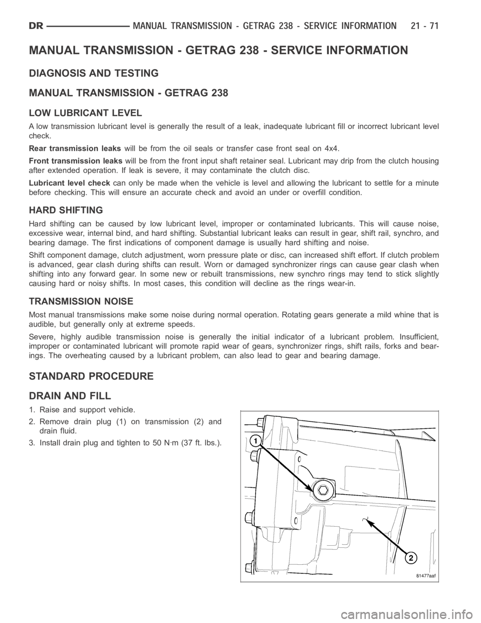
DRAIN AND FILL
1. Raise and support vehicle.
2. Remove drain plug (1) on transmission (2) and
drain fluid.
3. Install drain plug and tighten to 50 Nꞏm (37 ft. lbs.).
Page 2664 of 5267
MANUAL TRANSMISSION-T56 - SERVICE INFORMATION
DIAGNOSIS AND TESTING
MANUAL TRANSMISSION - T56
LOW LUBRICANT LEVEL
A low transmission lubricant level is generally the result of a leak, inadequate lubricant fill or incorrect lubricant level
check.
Rear transmission leakswill be from the oil seals or component mating surfaces.
Front transmission leakswill be from the front bearing retainer or retainer seal. Lubricant may dripfromtheclutch
housing after extended operation. If leak is severe, it may contaminate the clutch disc.
Lubricant level checkcan only be made when the vehicle is level and allowing the lubricant to settle for a minute
before checking. This will ensure an accurate check and avoid an underfillor overfill condition.
HARD SHIFTING
Hard shifting is usually caused by low lubricant level, improper or contaminated lubricants. This will cause noise,
excessive wear, internal bind, and hard shifting. Substantial lubricantleaks can result in gear, shift rail, synchro, and
bearing damage. The first indications of component damage is usually hardshifting and noise.
Shift component damage, clutch adjustment, worn pressure plate or disc are also causes of increased shift effort. If
clutch problem is advanced, gear clash during shifts can result. Worn or damaged synchro rings can cause gear
clash when shifting into any forward gear. In some new or rebuilt transmissions, new synchro rings may tend to stick
slightly causing hard or noisy shifts. In most cases, this condition will decline as the rings wear-in.
TRANSMISSION NOISE
Most manual transmissions make some noise during normal operation. Rotating gears generate a mild whine that is
audible, but generally only at extreme speeds.
Severe, highly audible transmission noise is generally the initial indicator of a lubricant problem. Insufficient,
improper or contaminated lubricant will promote rapid wear of gears, synchros, shift rails, forks and bearings. The
overheating caused by a lubricant problem, can also lead to gear and bearing damage.
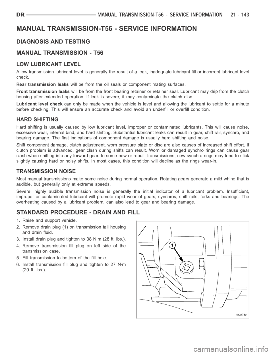
STANDARD PROCEDURE - DRAIN AND FILL
1. Raise and support vehicle.
2. Remove drain plug (1) on transmission tail housing
and drain fluid.
3. Install drain plug and tighten to 38 Nꞏm (28 ft. lbs.).
4. Remove transmission fill plug on left side of the
transmission case.
5. Fill transmission to bottom of the fill hole.
6. Install transmission fill plug and tighten to 27 Nꞏm
(20 ft. lbs.).
Page 2771 of 5267
P0731-GEAR RATIO ERROR IN 1ST
For a complete wiring diagramRefer to Section 8W.
When Monitored:
The Transmission gear ratio is monitored continuously while the transmission is in gear.
Set Condition:
If the ratio of the Input RPM to the Output RPM does not match the current gearratio when compared to the
known gear ratio.
Possible Causes
RELATED TRANSMISSION DTCS PRESENT
INTERMITTENT GEAR RATIO ERRORS
INTERNAL TRANSMISSION
Always perform the 42RLE Pre-Diagnostic Troubleshooting procedure before proceeding. (Refer to 21 -
TRANSMISSION/TRANSAXLE/AUTOMATIC - 42RLE - STANDARD PROCEDURE)
Theory of Operation
The transmission system uses two speed sensors, one to measure input RPM and one to measure output RPM.
These inputs are essential for proper transmission operation. Therefore, the integrity of this data is verified through
data checks. When in gear, if the gear ratio does not compare to a known gear ratio, the corresponding gear ratio
error trouble code is set. The transmission will go into Limp-in mode afterfour gear ratio error events occur in a
given driving cycle.
Diagnostic Test
1.DETERMINING IF RELATED TRANSMISSION DTCS ARE PRESENT
With the scan tool, read Transmission DTCs.
If any of these DTCs are present, perform their respective tests first.
Are there any Loss of Prime, Line Pressure Sensor and/or Speed Sensor DTCs present?
Ye s>>
Refer to appropriate diagnostic procedure in the Transmission category.If any of these DTC’s are
present, they will cause a gear ratio error. Perform the test for Loss of Primefirstifitispresent.
No>>
Go To 2
2.CHECK TO SEE IF P0731 IS CURRENT
With the scan tool, perform the 1st gear clutch test. Follow the instructions on the scan tool.
Increase the throttle angle or TPS Degree to 30° for no more than a few seconds.
CAUTION: Do not overheat the transmission.
Did the Clutch Test pass, Input Speed remain at zero?
Ye s>>
Go To 3
No>>
Repair internal Transmission as necessary. Check all of the components relatedtotheUDandLR
clutches. Inspect the Oil Pump and repair or replace as necessary. Refer tothe Service Information for
the proper repair procedures.
Perform 42RLE TRANSMISSION VERIFICATION TEST - VER 1. (Refer to 21 - TRANSMISSION/
TRANSAXLE/AUTOMATIC - 42RLE - STANDARD PROCEDURE)
Page 2774 of 5267
3.CHECK FOR INTERMITTENT OPERATION
The conditions to set this DTC are not current at this time.
Check the gearshift linkage adjustment.
Gear ratio DTCs can be set by problems in the Input and Output Speed Sensor circuits. If the vehicle passes the
Clutch Test and still sets Gear Ratio DTC, check the Speed Sensors for proper operation.
Remove the Ignition Switch Feed fuse from the TIPM.
CAUTION: Removal of the Ignition Switch Feed fuse from the TIPM will prevent the vehicle from being
startedingear.
WARNING: The Ignition Switch Feed fuse must be removed from the TIPM. Failure to do so can result in
personal injury or death.
Install the Transmission Simulator,Miller tool #8333 and the ElectronicTransmission Adapter kit.
Check the wiring and connectors to the Speed Sensors for a good connection,then perform a wiggle test using the
Transmission Simulator.
This DTC can also be set under extreme temperature conditions. This is usually caused by an internal problem.
Verify if the problem is only experienced under extreme hot or cold conditions.
With the scan tool, check the DTC EVENT DATA to help identify the conditionsin which the DTC was set.
Were there any problems found?
Ye s>>
Repair as necessary.
Perform 42RLE TRANSMISSION VERIFICATION TEST - VER 1. (Refer to 21 - TRANSMISSION/
TRANSAXLE/AUTOMATIC - 42RLE - STANDARD PROCEDURE)
No>>
Te s t C o m p l e t e .
4.CHECKFORRELATEDPRESSURESWITCHDTCS
With the scan tool, read Transmission DTC’s.
Are the DTCs P0845 and/or P0846 present also?
Ye s>>
Replace the Transmission Solenoid/Pressure Switch Assembly per the Service Information.
Perform 42RLE TRANSMISSION VERIFICATION TEST - VER 1. (Refer to 21 - TRANSMISSION/
TRANSAXLE/AUTOMATIC - 42RLE - STANDARD PROCEDURE)
No>>
Repair internal Transmission per the Service Information. Check all of the components related to the UD
and 2/4 clutches. Inspect the Oil Pump and repair or replace as necessary.
Perform 42RLE TRANSMISSION VERIFICATION TEST - VER 1. (Refer to 21 - TRANSMISSION/
TRANSAXLE/AUTOMATIC - 42RLE - STANDARD PROCEDURE)