2006 DODGE RAM SRT-10 oil pressure
[x] Cancel search: oil pressurePage 2367 of 5267
VALVE - FUEL PRESSURE LIMITING
DESCRIPTION
The fuel pressure limiting valve is located on the top of the fuel rail.
OPERATION
Fuel pressure at the fuel rail is monitored by the fuel rail pressure sensor. If fuel pressure becomes excessive, the
pressure limiting valve opens and vents excess pressure into the fuel draincircuit.
REMOVAL
CAUTION: Cleanliness cannot be overemphasized when handling or replacingdieselfuelsystemcompo-
nents. This especially includes the fuel injectors, high-pressure fuel lines and fuel injection pump. Very tight
tolerances are used with these parts. Dirt contamination could cause rapid part wear and possible plugging
of fuel injector nozzle tip holes. This in turn could lead to possible engine misfire. Always wash/clean any
fuel system component thoroughly before disassembly and then air dry. Capor cover any open part after
disassembly. Before assembly, examine each part for dirt, grease or othercontaminants and clean if nec-
essary. When installing new parts, lubricate them with clean engine oil orclean diesel fuel only.
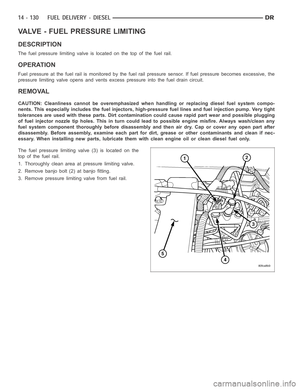
The fuel pressure limiting valve (3) is located on the
top of the fuel rail.
1. Thoroughly clean area at pressure limiting valve.
2. Remove banjo bolt (2) at banjo fitting.
3. Remove pressure limiting valve from fuel rail.
Page 2384 of 5267
ACTUATOR - FUEL CONTROL
DESCRIPTION
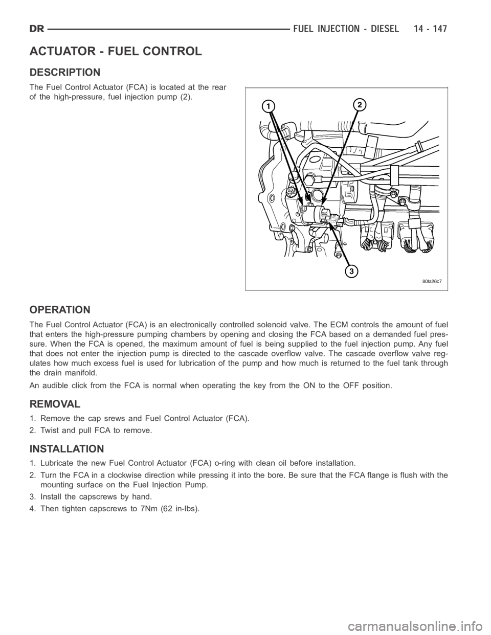
The Fuel Control Actuator (FCA) is located at the rear
of the high-pressure, fuel injection pump (2).
OPERATION
The Fuel Control Actuator (FCA) is an electronically controlled solenoidvalve. The ECM controls the amount of fuel
that enters the high-pressure pumping chambers by opening and closing theFCA based on a demanded fuel pres-
sure. When the FCA is opened, the maximum amount of fuel is being supplied tothe fuel injection pump. Any fuel
that does not enter the injection pump is directed to the cascade overflow valve. The cascade overflow valve reg-
ulates how much excess fuel is used for lubrication of the pump and how much is returned to the fuel tank through
the drain manifold.
An audible click from the FCA is normal when operating the key from the ON to the OFF position.
REMOVAL
1. Remove the cap srews and Fuel Control Actuator (FCA).
2. Twist and pull FCA to remove.
INSTALLATION
1. Lubricate the new Fuel Control Actuator (FCA) o-ring with clean oil before installation.
2. Turn the FCA in a clockwise direction while pressing it into the bore. Be sure that the FCA flange is flush with the
mounting surface on the Fuel Injection Pump.
3. Install the capscrews by hand.
4. Then tighten capscrews to 7Nm (62 in-lbs).
Page 2391 of 5267
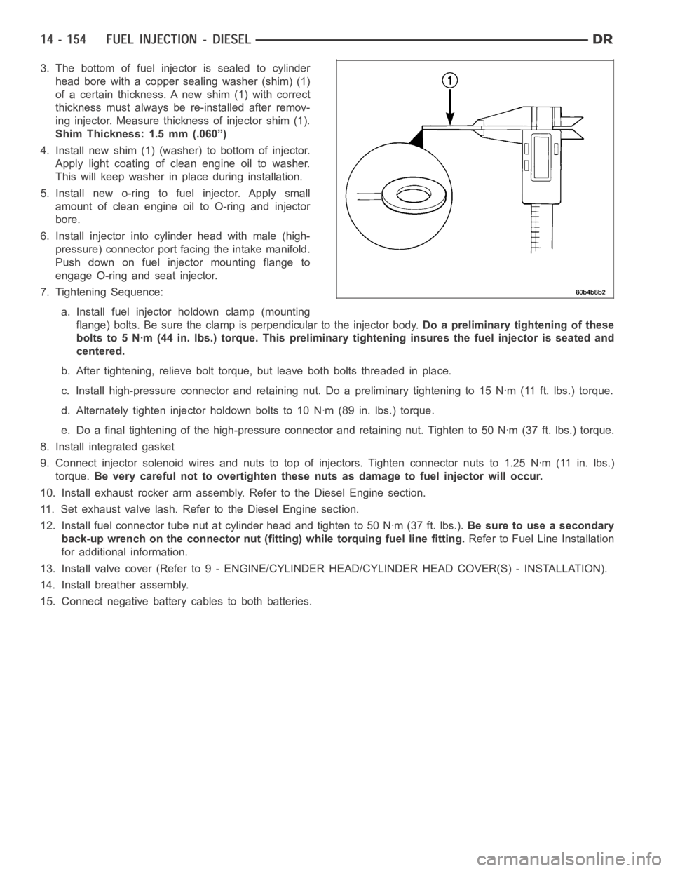
3. The bottom of fuel injector is sealed to cylinder
head bore with a copper sealing washer (shim) (1)
of a certain thickness. A new shim (1) with correct
thickness must always be re-installed after remov-
ing injector. Measure thickness of injector shim (1).
Shim Thickness: 1.5 mm (.060”)
4. Install new shim (1) (washer) to bottom of injector.
Apply light coating of clean engine oil to washer.
This will keep washer in place during installation.
5. Install new o-ring to fuel injector. Apply small
amount of clean engine oil to O-ring and injector
bore.
6. Install injector into cylinder head with male (high-
pressure) connector port facing the intake manifold.
Push down on fuel injector mounting flange to
engage O-ring and seat injector.
7. Tightening Sequence:
a. Install fuel injector holdown clamp (mounting
flange) bolts. Be sure the clamp is perpendicular to the injector body.Do a preliminary tightening of these
bolts to 5 Nꞏm (44 in. lbs.) torque. This preliminary tightening insures the fuel injector is seated and
centered.
b. After tightening, relieve bolt torque, but leave both bolts threaded inplace.
c. Install high-pressure connector and retaining nut. Do a preliminary tightening to 15 Nꞏm (11 ft. lbs.) torque.
d. Alternately tighten injector holdown bolts to 10 Nꞏm (89 in. lbs.) torque.
e. Do a final tightening of the high-pressure connector and retaining nut.Tighten to 50 Nꞏm (37 ft. lbs.) torque.
8. Install integrated gasket
9. Connect injector solenoid wires and nuts to top of injectors. Tighten connector nuts to 1.25 Nꞏm (11 in. lbs.)
torque.Be very careful not to overtighten these nuts as damage to fuel injector willoccur.
10. Install exhaust rocker arm assembly. Refer to the Diesel Engine section.
11. Set exhaust valve lash. Refer to the Diesel Engine section.
12. Install fuel connector tube nut at cylinder head and tighten to 50 Nꞏm (37ft.lbs.).Be sure to use a secondary
back-up wrench on the connector nut (fitting) while torquing fuel line fitting.Refer to Fuel Line Installation
for additional information.
13. Install valve cover (Refer to 9 - ENGINE/CYLINDER HEAD/CYLINDER HEAD COVER(S) - INSTALLATION).
14. Install breather assembly.
15. Connect negative battery cables to both batteries.
Page 2392 of 5267
FUEL INJECTOR RAIL
DESCRIPTION
The fuel injector rail is bolted to the top of the intake manifold.
OPERATION
The fuel rail is used as a distribution device to supply high-pressure fuelto the high-pressure fuel lines.
REMOVAL
CAUTION: Cleanliness cannot be overemphasized when handling or replacingdieselfuelsystemcompo-
nents. This especially includes the fuel injectors, high-pressure fuel lines and fuel injection pump. Very tight
tolerances are used with these parts. Dirt contamination could cause rapid part wear and possible plugging
of fuel injector nozzle tip holes. This in turn could lead to possible engine misfire. Always wash/clean any
fuel system component thoroughly before disassembly and then air dry. Capor cover any open part after
disassembly. Before assembly, examine each part for dirt, grease or othercontaminants and clean if nec-
essary. When installing new parts, lubricate them with clean engine oil orclean diesel fuel only.
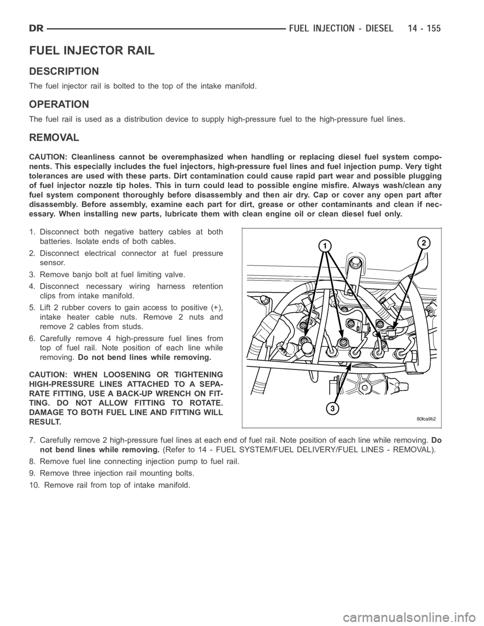
1. Disconnect both negative battery cables at both
batteries. Isolate ends of both cables.
2. Disconnect electrical connector at fuel pressure
sensor.
3. Remove banjo bolt at fuel limiting valve.
4. Disconnect necessary wiring harness retention
clips from intake manifold.
5. Lift 2 rubber covers to gain access to positive (+),
intake heater cable nuts. Remove 2 nuts and
remove 2 cables from studs.
6. Carefully remove 4 high-pressure fuel lines from
top of fuel rail. Note position of each line while
removing.Do not bend lines while removing.
CAUTION: WHEN LOOSENING OR TIGHTENING
HIGH-PRESSURE LINES ATTACHED TO A SEPA-
RATE FITTING, USE A BACK-UP WRENCH ON FIT-
TING. DO NOT ALLOW FITTING TO ROTATE.
DAMAGE TO BOTH FUEL LINE AND FITTING WILL
RESULT.
7. Carefully remove 2 high-pressure fuel lines at each end of fuel rail. Note position of each line while removing.Do
not bend lines while removing.(Refer to 14 - FUEL SYSTEM/FUEL DELIVERY/FUEL LINES - REMOVAL).
8. Remove fuel line connectinginjection pump to fuel rail.
9. Remove three injection rail mounting bolts.
10. Remove rail from top of intake manifold.
Page 2406 of 5267
STEERING
TABLE OF CONTENTS
page page
STEERING
DESCRIPTION ................................. 2
OPERATION ................................... 2
DIAGNOSIS AND TESTING
POWER STEERING SYSTEM ................. 2
POWER STEERING FLOW AND PRESSURE . . . 4
SPECIAL TOOLS
STEERING .................................. 6COLUMN...............................7
GEAR - INDEPENDENT FRONT SUSPENSION..38
GEAR - LINK/COIL.......................43
LINKAGE - INDEPENDENT FRONT
SUSPENSION...........................62
LINKAGE - LINK/COIL....................66
PUMP.................................76
PUMP - SRT10..........................92
Page 2407 of 5267
STEERING
DESCRIPTION
CAUTION: MOPARATF+4 is to be used in the power steering system. No other power steering or auto-
matic transmission fluid is to be used in the system. Damage may result to the power steering pump and
system if any other fluid is used, and do not overfill.
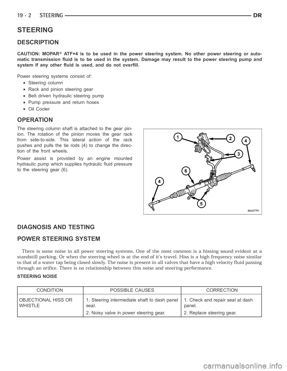
Power steering systems consist of:
Steering column
Rack and pinion steering gear
Belt driven hydraulic steering pump
Pump pressure and return hoses
Oil Cooler
OPERATION
The steering column shaft isattached to the gear pin-
ion. The rotation of the pinion moves the gear rack
from side-to-side. This lateral action of the rack
pushes and pulls the tie rods (4) to change the direc-
tion of the front wheels.
Power assist is provided by an engine mounted
hydraulic pump which supplies hydraulic fluid pressure
to the steering gear (6).
DIAGNOSIS AND TESTING
POWER STEERING SYSTEM
STEERING NOISE
CONDITION POSSIBLE CAUSES CORRECTION
OBJECTIONAL HISS OR
WHISTLE1. Steering intermediate shaft to dash panel
seal.1. Check and repair seal at dash
panel.
2. Noisy valve in power steering gear. 2. Replace steering gear.
Page 2481 of 5267
page page
PUMP
DESCRIPTION ................................ 77
OPERATION .................................. 77
DIAGNOSIS AND TESTING
PUMP LEAKAGE ............................ 77
STANDARD PROCEDURE
FLUSHING POWER STEERING SYSTEM . . . . . 77
POWER STEERING PUMP - INITIAL
OPERATION................................ 78
REMOVAL
GAS ENGINE ............................... 79
DIESEL ENGINE............................ 79
INSTALLATION
GAS ENGINE ............................... 80
DIESEL ENGINE............................ 80
SPECIFICATIONS
TORQUE ................................... 81
FLUID
DESCRIPTION ................................ 82
STANDARD PROCEDURE
POWER STEERING FLUID LEVEL
CHECKING................................. 82
FLUID COOLER
REMOVAL .................................... 83
INSTALLATION ............................... 83
HOSES - I.F.S.
REMOVAL
RETURN HOSE - GEAR TO COOLER ......... 85PRESSURE HOSE .......................... 85
RETURN HOSE - RESERVOIR TO COOLER . . 85
INSTALLATION
RETURN HOSE - GEAR TO COOLER ......... 86
PRESSURE HOSE .......................... 86
RETURN HOSE - RESERVOIR TO COOLER . . 86
HOSES - LINK/COIL
REMOVAL
RETURN HOSE - GEAR TO COOLER ......... 87
PRESSURE HOSE .......................... 87
RETURN HOSE - RESERVOIR TO COOLER . . 87
INSTALLATION
RETURN HOSE - GEAR TO COOLER ......... 88
PRESSURE HOSE .......................... 88
RETURN HOSE - RESERVOIR TO COOLER . . 88
SWITCH-POWER STEERING PRESSURE
DESCRIPTION ................................ 89
OPERATION .................................. 89
REMOVAL - 5.7L - HD VEHICLES ONLY ......... 89
INSTALLATION - 5.7L - HD VEHICLES ONLY .... 89
PULLEY
REMOVAL .................................... 90
INSTALLATION ............................... 90
RESERVOIR
REMOVAL .................................... 91
INSTALLATION ............................... 91
Page 2487 of 5267
FLUID
DESCRIPTION
NOTE: It is normal that some pressure will build up inside the reservoir, especially, with a warm vehicle. A
slight popping noise upon removal ofthe cap is normal. The fluid level should read between the ADD and
the FULL COLD marks. When the fluid is hotit should read between ADD and FULLHOT marks. Only add
fluid when the vehicle is cold.
The recommended fluid for the power steering system is Mopar
AT F + 4 .
Mopar
ATF+4, when new is red in color. The ATF+4 is dyed red so it can be identified from other fluids used in the
vehicle such as engine oil or antifreeze. The red color is not permanent andis not an indicator of fluid condition, As
the vehicle is driven, the ATF+4 will begin to look darker in color and may eventually become brown.THIS IS NOR-
MAL.ATF+4 also has a unique odor that may change with age. Consequently, odor and color cannot be used to
indicate the fluid condition or the need for a fluid change.
STANDARD PROCEDURE
POWER STEERING FLUID LEVEL CHECKING
WARNING: FLUID LEVEL SHOULD BE CHECKED WITH THE ENGINE OFF TO PREVENT PERSONAL INJURY
FROM MOVING PARTS.
CAUTION: MOPAR
ATF+4 is to be used in the power steering system. No other power steering or auto-
matic transmission fluid is to be used in the system. Damage may result to the power steering pump and
system if any other fluid is used, and do not overfill.
The power steering fluid level can be viewed on the dipstick attached to thefiller cap. There are two ranges listed
on the dipstick, COLD and HOT. Before opening power steering system, wipe the reservoir filler cap free of dirt and
debris. Remove the cap and check the fluid level on its dipstick. When the fluid is at normal ambient temperature,
approximately 21°C to 27°C (70°F to 80°F), the fluid level should read between the minimum and maximum area of
the cold range. When the fluid is hot, fluid level is allowed to read up to thehighest end of the HOT range. Only add
fluid when the vehicle is cold.
Use only Mopar
AT F + 4 .Do not overfill the power steering system.