2006 DODGE RAM SRT-10 oil pressure
[x] Cancel search: oil pressurePage 5166 of 5267
INSTALLATION
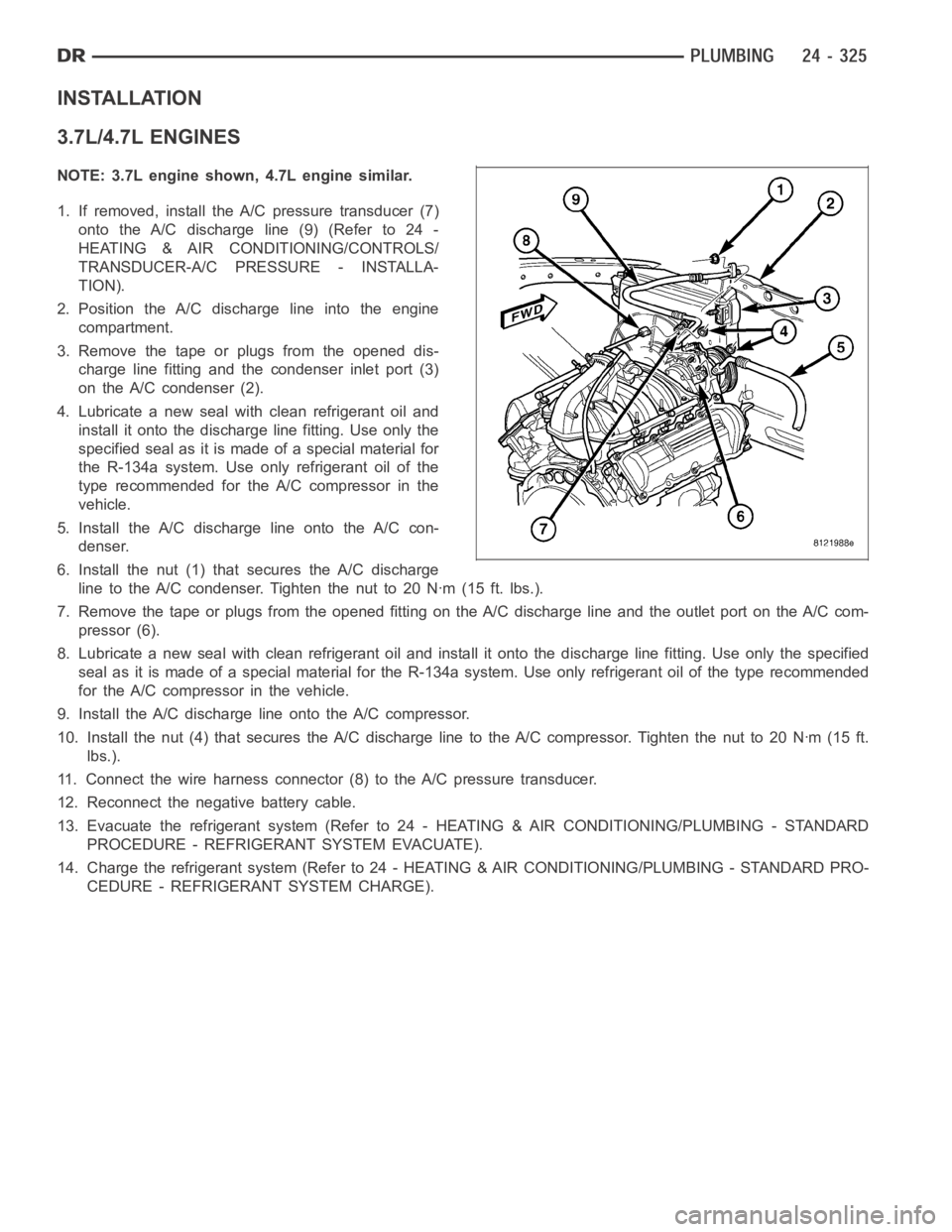
3.7L/4.7L ENGINES
NOTE: 3.7L engine shown, 4.7L engine similar.
1. If removed, install the A/C pressure transducer (7)
onto the A/C discharge line (9) (Refer to 24 -
HEATING & AIR CONDITIONING/CONTROLS/
TRANSDUCER-A/C PRESSURE - INSTALLA-
TION).
2. Position the A/C discharge line into the engine
compartment.
3. Remove the tape or plugs from the opened dis-
charge line fitting and the condenser inlet port (3)
on the A/C condenser (2).
4. Lubricate a new seal with clean refrigerant oil and
install it onto the discharge line fitting. Use only the
specified seal as it is made of a special material for
the R-134a system. Use only refrigerant oil of the
type recommended for the A/C compressor in the
vehicle.
5. Install the A/C discharge line onto the A/C con-
denser.
6. Install the nut (1) that secures the A/C discharge
line to the A/C condenser. Tighten the nut to 20 Nꞏm (15 ft. lbs.).
7. Remove the tape or plugs from the opened fitting on the A/C discharge lineand the outlet port on the A/C com-
pressor (6).
8. Lubricate a new seal with clean refrigerant oil and install it onto the discharge line fitting. Use only the specified
seal as it is made of a special material for the R-134a system. Use only refrigerant oil of the type recommended
for the A/C compressor in the vehicle.
9. Install the A/C discharge line onto the A/C compressor.
10. Install the nut (4) that secures the A/C discharge line to the A/C compressor.Tightenthenutto20Nꞏm(15ft.
lbs.).
11. Connect the wire harness connector (8) to the A/C pressure transducer.
12. Reconnect the negative battery cable.
13. Evacuate the refrigerant system (Refer to 24 - HEATING & AIR CONDITIONING/PLUMBING - STANDARD
PROCEDURE - REFRIGERANT SYSTEM EVACUATE).
14. Charge the refrigerant system (Refer to 24 - HEATING & AIR CONDITIONING/PLUMBING - STANDARD PRO-
CEDURE - REFRIGERANT SYSTEM CHARGE).
Page 5167 of 5267
5.7L ENGINE
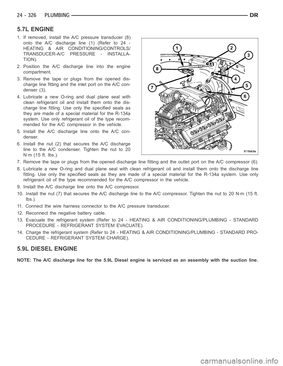
1. If removed, install the A/C pressure transducer (8)
onto the A/C discharge line (1) (Refer to 24 -
HEATING & AIR CONDITIONING/CONTROLS/
TRANSDUCER-A/C PRESSURE - INSTALLA-
TION).
2. Position the A/C discharge line into the engine
compartment.
3. Remove the tape or plugs from the opened dis-
charge line fitting and the inlet port on the A/C con-
denser (3).
4. Lubricate a new O-ring and dual plane seal with
clean refrigerant oil and install them onto the dis-
charge line fitting. Use only the specified seals as
they are made of a special material for the R-134a
system. Use only refrigerant oil of the type recom-
mended for the A/C compressor in the vehicle.
5. Install the A/C discharge line onto the A/C con-
denser.
6. Install the nut (2) that secures the A/C discharge
line to the A/C condenser. Tighten the nut to 20
Nꞏm (15 ft. lbs.).
7. Remove the tape or plugs from the opened discharge line fitting and the outlet port on the A/C compressor (6).
8. Lubricate a new O-ring and dual plane seal with clean refrigerant oil andinstall them onto the discharge line
fitting. Use only the specified seals as they are made of a special materialfor the R-134a system. Use only
refrigerant oil of the type recommended for the A/C compressor in the vehicle.
9. Install the A/C discharge line onto the A/C compressor.
10. Install the nut (7) that secures the A/C discharge line to the A/C compressor.Tightenthenutto20Nꞏm(15ft.
lbs.).
11. Connect the wire harness connector to the A/C pressure transducer.
12. Reconnect the negative battery cable.
13. Evacuate the refrigerant system (Refer to 24 - HEATING & AIR CONDITIONING/PLUMBING - STANDARD
PROCEDURE - REFRIGERANT SYSTEM EVACUATE).
14. Charge the refrigerant system (Refer to 24 - HEATING & AIR CONDITIONING/PLUMBING - STANDARD PRO-
CEDURE - REFRIGERANT SYSTEM CHARGE).
5.9L DIESEL ENGINE
NOTE: The A/C discharge line for the 5.9L Diesel engine is serviced as an assembly with the suction line.
Page 5168 of 5267
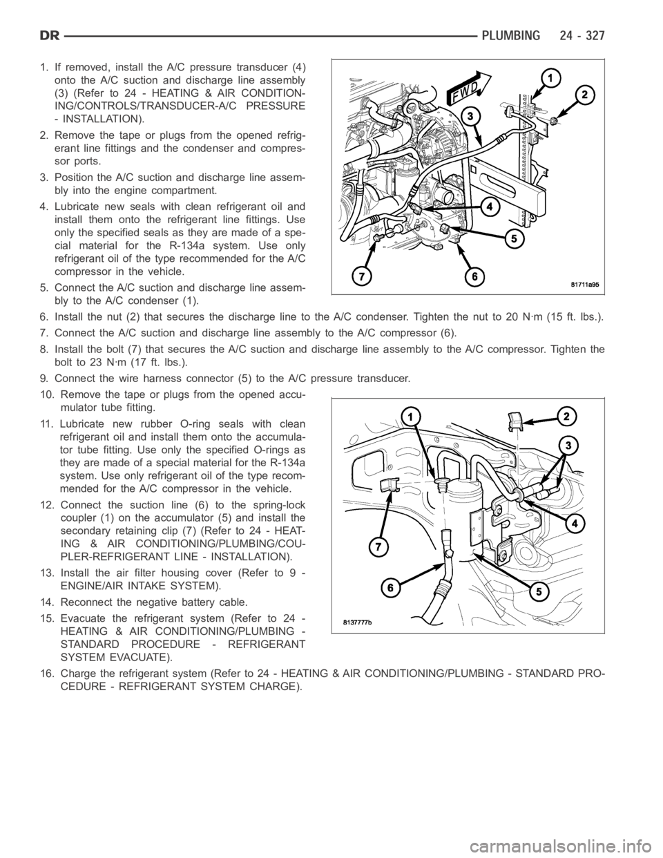
1. If removed, install the A/C pressure transducer (4)
onto the A/C suction and discharge line assembly
(3)(Referto24-HEATING&AIRCONDITION-
ING/CONTROLS/TRANSDUCER-A/C PRESSURE
- INSTALLATION).
2. Remove the tape or plugs from the opened refrig-
erant line fittings and the condenser and compres-
sor ports.
3. Position the A/C suction and discharge line assem-
bly into the engine compartment.
4. Lubricate new seals with clean refrigerant oil and
install them onto the refrigerant line fittings. Use
only the specified seals as they are made of a spe-
cial material for the R-134a system. Use only
refrigerant oil of the type recommended for the A/C
compressor in the vehicle.
5. Connect the A/C suction and discharge line assem-
bly to the A/C condenser (1).
6. Install the nut (2) that secures the discharge line to the A/C condenser.Tighten the nut to 20 Nꞏm (15 ft. lbs.).
7. Connect the A/C suction and discharge line assembly to the A/C compressor(6).
8. Install the bolt (7) that secures the A/C suction and discharge line assembly to the A/C compressor. Tighten the
boltto23Nꞏm(17ft.lbs.).
9. Connect the wire harness connector (5) to the A/C pressure transducer.
10. Remove the tape or plugs from the opened accu-
mulator tube fitting.
11. Lubricate new rubber O-ring seals with clean
refrigerant oil and install them onto the accumula-
tor tube fitting. Use only the specified O-rings as
they are made of a special material for the R-134a
system. Use only refrigerant oil of the type recom-
mended for the A/C compressor in the vehicle.
12. Connect the suction line (6) to the spring-lock
coupler (1) on the accumulator (5) and install the
secondary retaining clip (7) (Refer to 24 - HEAT-
ING & AIR CONDITIONING/PLUMBING/COU-
PLER-REFRIGERANT LINE - INSTALLATION).
13. Install the air filter housing cover (Refer to 9 -
ENGINE/AIR INTAKE SYSTEM).
14. Reconnect the negative battery cable.
15. Evacuate the refrigerant system (Refer to 24 -
HEATING & AIR CONDITIONING/PLUMBING -
STANDARD PROCEDURE - REFRIGERANT
SYSTEM EVACUATE).
16. Charge the refrigerant system (Refer to 24 - HEATING & AIR CONDITIONING/PLUMBING - STANDARD PRO-
CEDURE - REFRIGERANT SYSTEM CHARGE).
Page 5169 of 5267
8.3L ENGINE
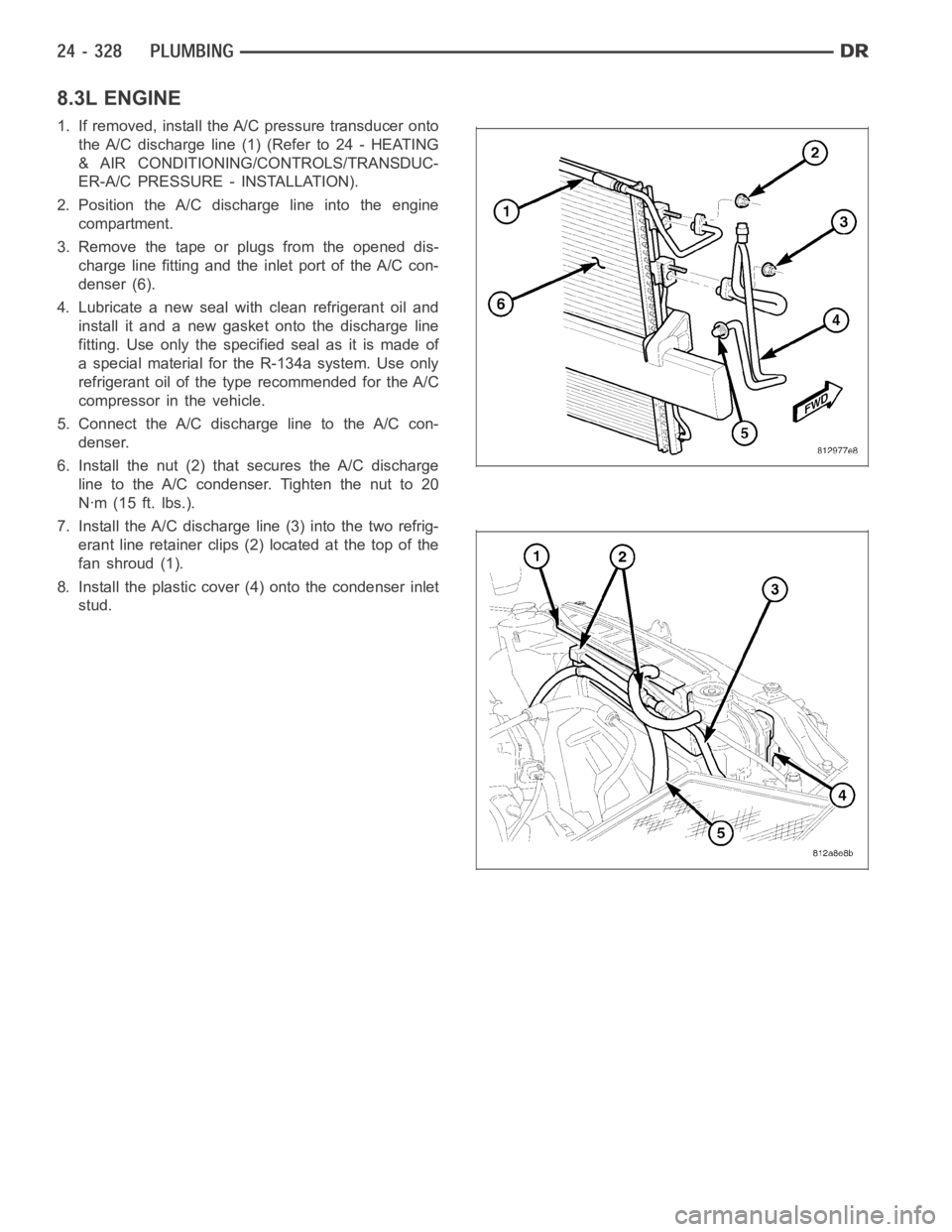
1. If removed, install the A/C pressure transducer onto
the A/C discharge line (1) (Refer to 24 - HEATING
& AIR CONDITIONING/CONTROLS/TRANSDUC-
ER-A/C PRESSURE - INSTALLATION).
2. Position the A/C discharge line into the engine
compartment.
3. Remove the tape or plugs from the opened dis-
charge line fitting and the inlet port of the A/C con-
denser (6).
4. Lubricate a new seal with clean refrigerant oil and
install it and a new gasket onto the discharge line
fitting. Use only the specified seal as it is made of
a special material for the R-134a system. Use only
refrigerant oil of the type recommended for the A/C
compressor in the vehicle.
5. Connect the A/C discharge line to the A/C con-
denser.
6. Install the nut (2) that secures the A/C discharge
line to the A/C condenser. Tighten the nut to 20
Nꞏm (15 ft. lbs.).
7. Install the A/C discharge line (3) into the two refrig-
erant line retainer clips (2) located at the top of the
fanshroud(1).
8. Install the plastic cover (4) onto the condenser inlet
stud.
Page 5170 of 5267
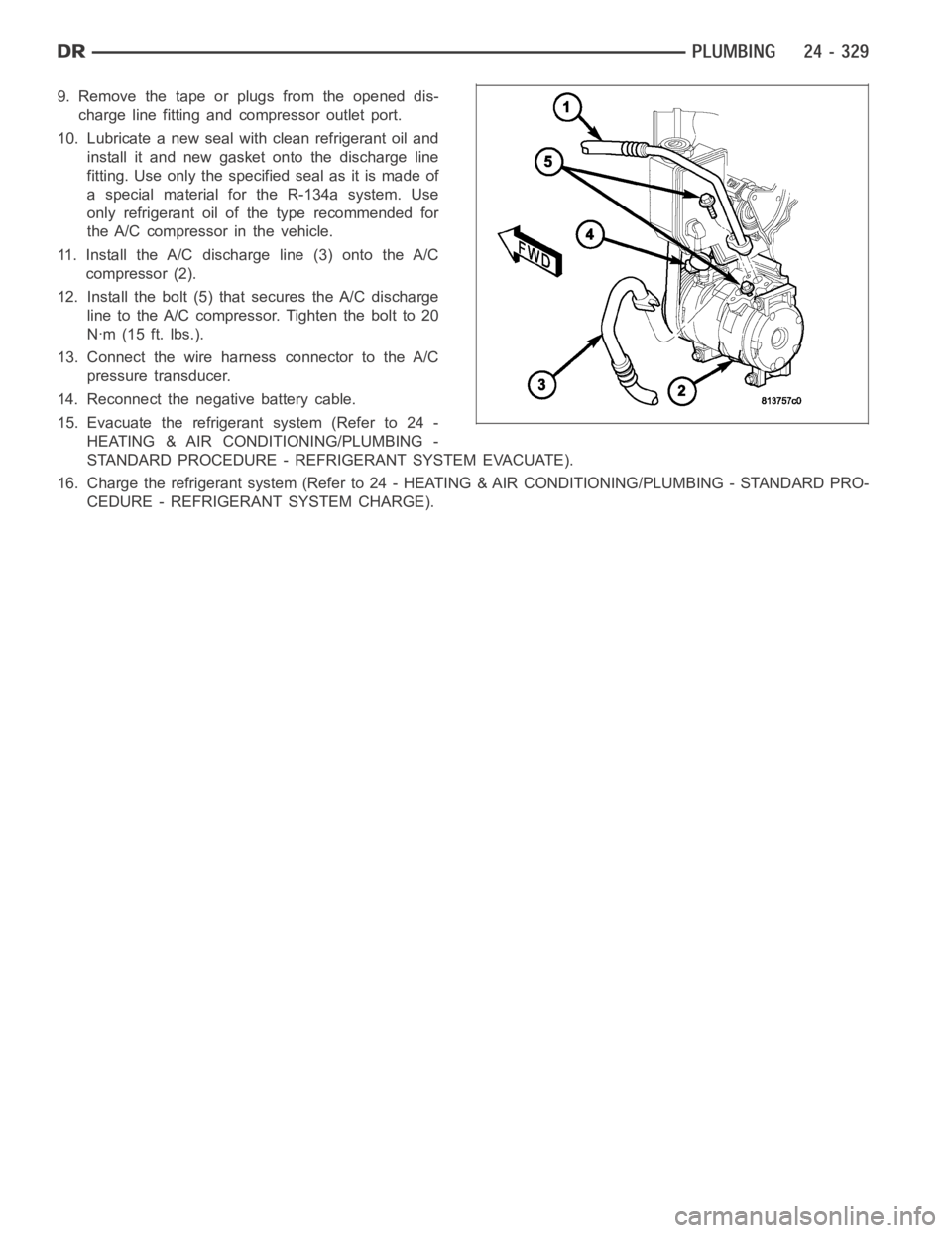
9. Remove the tape or plugs from the opened dis-
charge line fitting and compressor outlet port.
10. Lubricate a new seal with clean refrigerant oil and
install it and new gasket onto the discharge line
fitting. Use only the specified seal as it is made of
a special material for the R-134a system. Use
only refrigerant oil of the type recommended for
the A/C compressor in the vehicle.
11. Install the A/C discharge line (3) onto the A/C
compressor (2).
12. Install the bolt (5) that secures the A/C discharge
line to the A/C compressor. Tighten the bolt to 20
Nꞏm (15 ft. lbs.).
13. Connect the wire harness connector to the A/C
pressure transducer.
14. Reconnect the negative battery cable.
15. Evacuate the refrigerant system (Refer to 24 -
HEATING & AIR CONDITIONING/PLUMBING -
STANDARD PROCEDURE - REFRIGERANT SYSTEM EVACUATE).
16. Charge the refrigerant system (Refer to 24 - HEATING & AIR CONDITIONING/PLUMBING - STANDARD PRO-
CEDURE - REFRIGERANT SYSTEM CHARGE).
Page 5185 of 5267
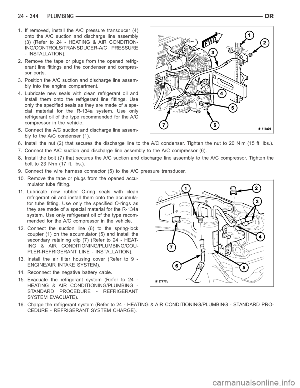
1. If removed, install the A/C pressure transducer (4)
onto the A/C suction and discharge line assembly
(3)(Referto24-HEATING&AIRCONDITION-
ING/CONTROLS/TRANSDUCER-A/C PRESSURE
- INSTALLATION).
2. Remove the tape or plugs from the opened refrig-
erant line fittings and the condenser and compres-
sor ports.
3. Position the A/C suction and discharge line assem-
bly into the engine compartment.
4. Lubricate new seals with clean refrigerant oil and
install them onto the refrigerant line fittings. Use
only the specified seals as they are made of a spe-
cial material for the R-134a system. Use only
refrigerant oil of the type recommended for the A/C
compressor in the vehicle.
5. Connect the A/C suction and discharge line assem-
bly to the A/C condenser (1).
6. Install the nut (2) that secures the discharge line to the A/C condenser.Tighten the nut to 20 Nꞏm (15 ft. lbs.).
7. Connect the A/C suction and discharge line assembly to the A/C compressor(6).
8. Install the bolt (7) that secures the A/C suction and discharge line assembly to the A/C compressor. Tighten the
boltto23Nꞏm(17ft.lbs.).
9. Connect the wire harness connector (5) to the A/C pressure transducer.
10. Remove the tape or plugs from the opened accu-
mulator tube fitting.
11. Lubricate new rubber O-ring seals with clean
refrigerant oil and install them onto the accumula-
tor tube fitting. Use only the specified O-rings as
they are made of a special material for the R-134a
system. Use only refrigerant oil of the type recom-
mended for the A/C compressor in the vehicle.
12. Connect the suction line (6) to the spring-lock
coupler (1) on the accumulator (5) and install the
secondary retaining clip (7) (Refer to 24 - HEAT-
ING & AIR CONDITIONING/PLUMBING/COU-
PLER-REFRIGERANT LINE - INSTALLATION).
13. Install the air filter housing cover (Refer to 9 -
ENGINE/AIR INTAKE SYSTEM).
14. Reconnect the negative battery cable.
15. Evacuate the refrigerant system (Refer to 24 -
HEATING & AIR CONDITIONING/PLUMBING -
STANDARD PROCEDURE - REFRIGERANT
SYSTEM EVACUATE).
16. Charge the refrigerant system (Refer to 24 - HEATING & AIR CONDITIONING/PLUMBING - STANDARD PRO-
CEDURE - REFRIGERANT SYSTEM CHARGE).
Page 5201 of 5267
Engine RPM— A live reading of engine RPM to aid the user in accessing the Similar Conditions Window.
Adaptive Memory Factor— The PCM utilizes both Short Term Compensation and Long Term Adaptive to
calculate the Adaptive Memory Factor for total fuel correction.
Upstream O2S Volts— A live reading of the Oxygen Sensor to indicate its performance. For example, stuck
lean, stuck rich, etc.
SCW Time in Window (Similar Conditions Window Time in Window)—Atimer used by the PCM that
indicates that, after all Similar Conditions have been met, if there has been enough good engine running time
in the SCW without failure detected. This timer is used to increment a Good Trip.
Fuel System Good Trip Counter—ATripCounterusedtoturnOFFtheMILforFuelSystemDTCs.To
increment a Fuel System Good Trip, the engine must be in the Similar Conditions Window, Adaptive Memory
Factor must be less than calibrated threshold and the Adaptive Memory Factor must stay below that threshold
for a calibrated amount of time.
Test Done This Trip— Indicates that the monitor has already been run and completed during the current trip.
MISFIRE
Same Misfire Warm-Up State— Indicates if the misfire occurred when the engine was warmed up above
160° F (71.1°C).
In Similar Misfire Window— An indicator that ’Absolute MAP When Misfire Occurred’ and ’RPM When Mis-
fire Occurred’ are all in the same range when the failure occurred. Indicated by switching from ’NO’ to ’YES’.
Absolute MAP When Misfire Occurred— The stored MAP reading at the time of failure. Informs the user at
what engine load the failure occurred.
Absolute MAP— A live reading of engine load to aid the user in accessing the Similar Conditions Window.
RPM When Misfire Occurred— The stored RPM reading at the time of failure. Informs the user at what
engine RPM the failure occurred.
Engine RPM— A live reading of engine RPM to aid the user in accessing the Similar Conditions Window.
Adaptive Memory Factor— The PCM utilizes both Short Term Compensation and Long Term Adaptive to
calculate the Adaptive Memory Factor for total fuel correction.
200 Rev Counter— Counts 0–100 720 degree cycles.
SCW Cat 200 Rev Counter— Counts when in similar conditions.
SCW FTP 1000 Rev Counter— Counts 0–4 when in similar conditions.
Misfire Good Trip Counter— Counts up to three to turn OFF the MIL.
Misfire Data— Data collected during test.
Test Done This Trip— Indicates YES when the test is done.
NON-MONITORED CIRCUITS
The PCM does not monitor the following circuits, systems and conditions that could have malfunctions causing
driveability problems. The PCM might not store diagnostic trouble codes for these conditions. However, problems
with these systems may cause the PCM to store diagnostic trouble codes for other systems or components.EXAM-
PLE:a fuel pressure problem will not register a fault directly, but could causea rich/lean condition or misfire. This
could cause the PCM to store an oxygen sensor or misfire diagnostic troublecode
FUEL PRESSURE
The fuel pressure regulator controls fuel system pressure. The PCM cannotdetect a clogged fuel pump inlet filter,
clogged in-line fuel filter, or a pinched fuel supply or return line. However, these could result in a rich or lean con-
dition causing the PCM to store an oxygen sensor or fuel system diagnostic trouble code.
SECONDARY IGNITION CIRCUIT
The PCM cannot detect an inoperative ignition coil, fouled or worn spark plugs, ignition cross firing, or open spark
plug cables.
CYLINDER COMPRESSION
The PCM cannot detect uneven, low, or high engine cylinder compression.