2006 DODGE RAM SRT-10 oil pressure
[x] Cancel search: oil pressurePage 3884 of 5267
SERVO-FRONT
DESCRIPTION
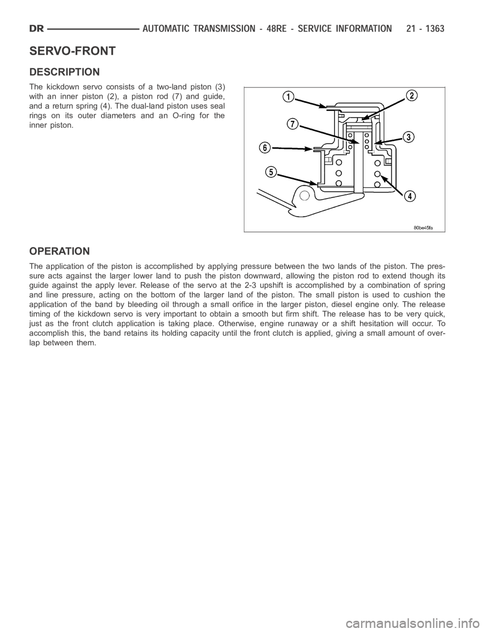
The kickdown servo consists of a two-land piston (3)
with an inner piston (2), a piston rod (7) and guide,
and a return spring (4). The dual-land piston uses seal
rings on its outer diameters and an O-ring for the
inner piston.
OPERATION
The application of the piston is accomplished by applying pressure between the two lands of the piston. The pres-
sure acts against the larger lower land to push the piston downward, allowing the piston rod to extend though its
guide against the apply lever. Release of the servo at the 2-3 upshift is accomplished by a combination of spring
and line pressure, acting on the bottom of the larger land of the piston. Thesmallpistonisusedtocushionthe
application of the band by bleeding oil through a small orifice in the larger piston, diesel engine only. The release
timing of the kickdown servo is very important to obtain a smooth but firm shift. The release has to be very quick,
just as the front clutch application is taking place. Otherwise, engine runaway or a shift hesitation will occur. To
accomplish this, the band retains itsholding capacity until the front clutch is applied, giving a small amount of over-
lap between them.
Page 3898 of 5267
CLUTCH-OVERDRIVE
DESCRIPTION
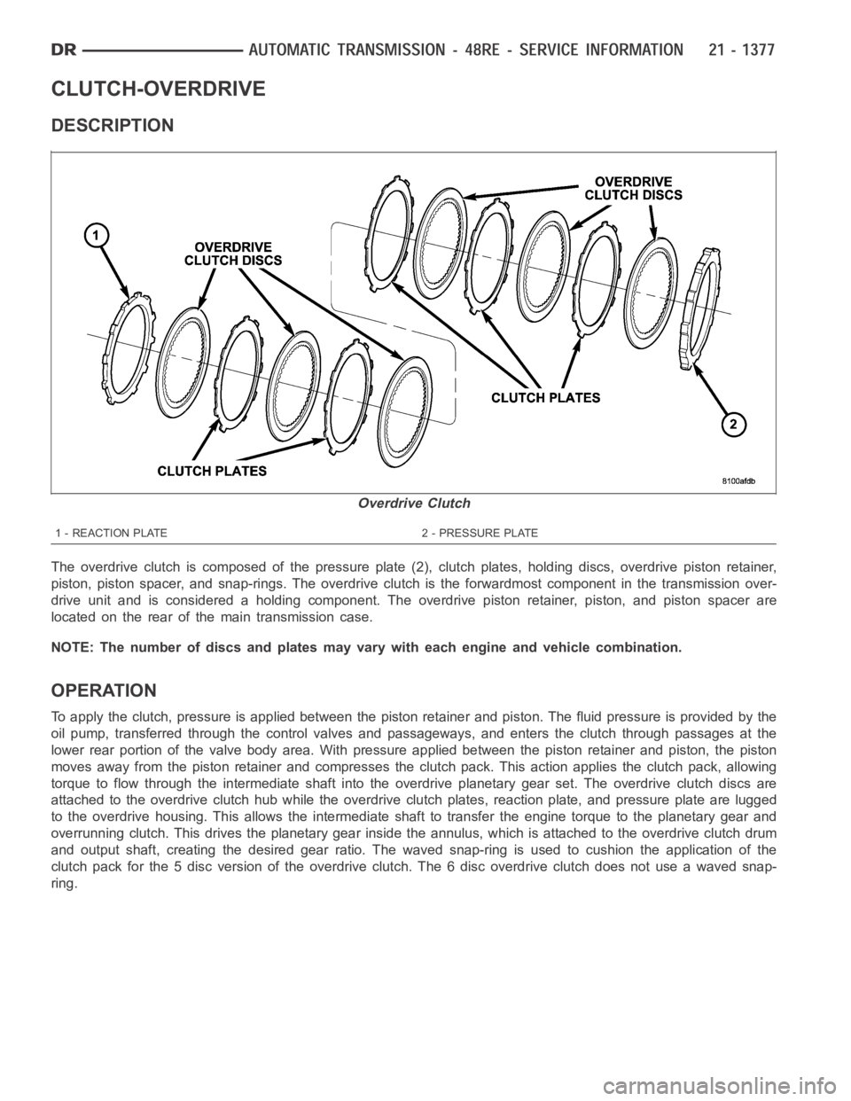
The overdrive clutch is composed of the pressure plate (2), clutch plates,holding discs, overdrive piston retainer,
piston, piston spacer, and snap-rings. The overdrive clutch is the forwardmost component in the transmission over-
drive unit and is considered a holding component. The overdrive piston retainer, piston, and piston spacer are
located on the rear of the main transmission case.
NOTE: The number of discs and plates may vary with each engine and vehicle combination.
OPERATION
To apply the clutch, pressure is applied between the piston retainer and piston. The fluid pressure is provided by the
oil pump, transferred through the control valves and passageways, and enters the clutch through passages at the
lower rear portion of the valve body area. With pressure applied between the piston retainer and piston, the piston
moves away from the piston retainer and compresses the clutch pack. This action applies the clutch pack, allowing
torque to flow through the intermediate shaft into the overdrive planetary gear set. The overdrive clutch discs are
attached to the overdrive clutch hub while the overdrive clutch plates, reaction plate, and pressure plate are lugged
to the overdrive housing. This allows the intermediate shaft to transfer the engine torque to the planetary gear and
overrunning clutch. This drives the planetary gear inside the annulus, which is attached to the overdrive clutch drum
and output shaft, creating the desired gear ratio. The waved snap-ring is used to cushion the application of the
clutch pack for the 5 disc version of the overdrive clutch. The 6 disc overdrive clutch does not use a waved snap-
ring.
Overdrive Clutch
1 - REACTION PLATE 2 - PRESSURE PLATE
Page 3937 of 5267
CLUTCH-REAR
DESCRIPTION
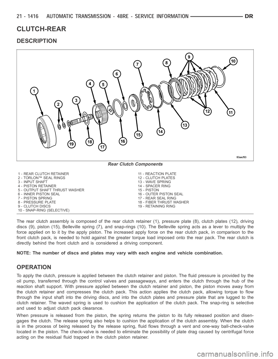
The rear clutch assembly is composed of the rear clutch retainer (1), pressure plate (8), clutch plates (12), driving
discs (9), piston (15), Belleville spring (7), and snap-rings (10). The Belleville spring acts as a lever to multiply the
force applied on to it by the apply piston. The increased apply force on the rear clutch pack, in comparison to the
front clutch pack, is needed to hold against the greater torque load imposed onto the rear pack. The rear clutch is
directly behind the front clutch and is considered a driving component.
NOTE: The number of discs and plates may vary with each engine and vehicle combination.
OPERATION
To apply the clutch, pressure is applied between the clutch retainer and piston. The fluid pressure is provided by the
oil pump, transferred through the control valves and passageways, and enters the clutch through the hub of the
reaction shaft support. With pressure applied between the clutch retainer and piston, the piston moves away from
the clutch retainer and compresses the clutch pack. This action applies the clutch pack, allowing torque to flow
through the input shaft into the driving discs, and into the clutch plates and pressure plate that are lugged to the
clutch retainer. The waved spring is used to cushion the application of theclutch pack. The snap-ring is selective
and used to adjust clutch pack clearance.
When pressure is released from the piston, the spring returns the piston toits fully released position and disen-
gages the clutch. The release spring also helps to cushion the applicationof the clutch assembly. When the clutch
is in the process of being released by the release spring, fluid flows through a vent and one-way ball-check-valve
located in the piston. The check-valve is needed to eliminate the possibility of plate drag caused by centrifugal force
acting on the residual fluid trapped in the clutch piston retainer.
Rear Clutch Components
1 - REAR CLUTCH RETAINER 11 - REACTION PLATE
2 - TORLON™ SEAL RINGS 12 - CLUTCH PLATES
3 - INPUT SHAFT 13 - WAVE SPRING
4 - PISTON RETAINER 14 - SPACER RING
5 - OUTPUT SHAFT THRUST WASHER 15 - PISTON
6 - INNER PISTON SEAL 16 - OUTER PISTON SEAL
7 - PISTON SPRING 17 - REAR SEAL RING
8 - PRESSURE PLATE 18 - FIBER THRUST WASHER
9 - CLUTCH DISCS 19 - RETAINING RING
10 - SNAP-RING (SELECTIVE)
Page 3957 of 5267
STATOR
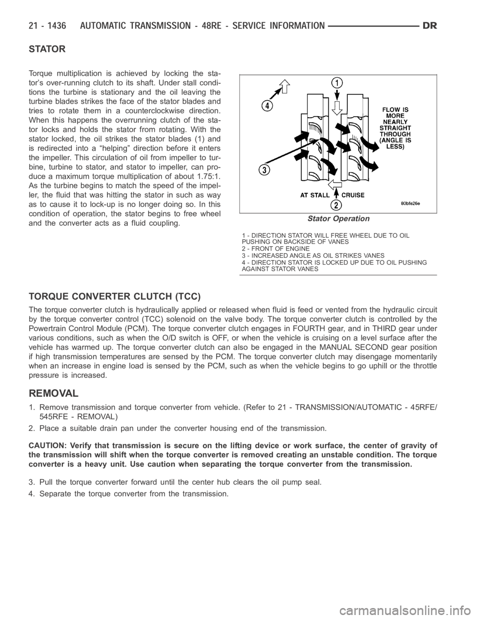
Torque multiplication is achieved by locking the sta-
tor’s over-running clutch to its shaft. Under stall condi-
tions the turbine is stationary and the oil leaving the
turbine blades strikes the face of the stator blades and
tries to rotate them in a counterclockwise direction.
When this happens the overrunning clutch of the sta-
tor locks and holds the stator from rotating. With the
stator locked, the oil strikes the stator blades (1) and
is redirected into a “helping” direction before it enters
the impeller. This circulation of oil from impeller to tur-
bine, turbine to stator, and stator to impeller, can pro-
duce a maximum torque multiplication of about 1.75:1.
As the turbine begins to match the speed of the impel-
ler, the fluid that was hitting the stator in such as way
as to cause it to lock-up is no longer doing so. In this
condition of operation, the stator begins to free wheel
and the converter acts as a fluid coupling.
TORQUE CONVERTER CLUTCH (TCC)
The torque converter clutch is hydraulically applied or released when fluid is feed or vented from the hydraulic circuit
by the torque converter control (TCC) solenoid on the valve body. The torque converter clutch is controlled by the
Powertrain Control Module (PCM). The torque converter clutch engages in FOURTH gear, and in THIRD gear under
various conditions, such as when the O/D switch is OFF, or when the vehicle is cruising on a level surface after the
vehicle has warmed up. The torque converter clutch can also be engaged in the MANUAL SECOND gear position
if high transmission temperatures are sensed by the PCM. The torque converter clutch may disengage momentarily
when an increase in engine load is sensed by the PCM, such as when the vehiclebegins to go uphill or the throttle
pressure is increased.
REMOVAL
1. Remove transmission and torque converter from vehicle. (Refer to 21 - TRANSMISSION/AUTOMATIC - 45RFE/
545RFE - REMOVAL)
2. Place a suitable drain pan under the converter housing end of the transmission.
CAUTION: Verify that transmission is secure on the lifting device or work surface, the center of gravity of
the transmission will shift when the torque converter is removed creatingan unstable condition. The torque
converter is a heavy unit. Use caution when separating the torque converter from the transmission.
3. Pull the torque converter forward until the center hub clears the oil pumpseal.
4. Separate the torque converter from the transmission.
Stator Operation
1 - DIRECTION STATOR WILL FREE WHEEL DUE TO OIL
PUSHING ON BACKSIDE OF VANES
2-FRONTOFENGINE
3 - INCREASED ANGLE AS OIL STRIKES VANES
4 - DIRECTION STATOR IS LOCKED UP DUE TO OIL PUSHING
AGAINST STATOR VANES
Page 3959 of 5267
VALVE-TORQUE CONVERTER DRAINBACK
DESCRIPTION
GAS ENGINES
The drainback valve is located in the transmission cooler outlet (pressure) line.
DIESEL ENGINE
The converter drainback check valve is located in the in the TOC pressure - supply line, between the engine
mounted TOC and the air to oil TOC.
OPERATION
GAS ENGINES
The valve prevents fluid from draining from the converter into the cooler and lines when the vehicle is shut down for
lengthy periods. Production valves have a hose nipple at one end, while theopposite end is threaded for a flare
fitting. All valves have an arrow (or similar mark) to indicate direction of flow through the valve.
DIESEL ENGINE
The valve prevents fluid from draining from the converter into the cooler and lines when the vehicle is shut down for
lengthy periods. Production valves have pipe thread on one end, while the opposite end is threaded for a flare
fitting, and are threaded into the oil cooler mounted on the side of the engine. All valves have an arrow (or similar
mark) to indicate direction of flow through the valve.
STANDARD PROCEDURE
GAS ENGINES
The converter drainback check valve is located in the cooler outlet (pressure) line near the radiator tank. The valve
prevents fluid drainback when the vehicle is parked for lengthy periods. The valve check ball is spring loaded and
has an opening pressure of approximately 2 psi.
The valve is serviced as an assembly; it is not repairable. Do not clean the valve if restricted, or contaminated by
sludge, or debris. If the valve fails, or if a transmission malfunction occurs that generates significant amounts of
sludge and/or clutch particles and metal shavings, the valve must be replaced.
If the valve is restricted, installed backwards, or in the wrong line, it will cause an transmission overheating condition
and possible transmission failure.
CAUTION: The drainback valve is a one-way flow device. It must be properly orientedintermsofflowdirec-
tion for the cooler to function properly. The valve must be installed in thepressure line. Otherwise flow will
be blocked and would cause an transmission overheating condition and eventual transmission failure.
DIESEL ENGINE
The converter drainback check valve is located in the in the TOC pressure - supply line, between the engine
mounted transmission oil cooler and the air to oil transmission oil cooler. The valve prevents fluid drainback when
the vehicle is parked for lengthy periods. The valve check ball is spring loaded and has an opening pressure of
approximately 2 psi.
The valve is serviced as an assembly; it is not repairable. Do not clean the valve if restricted, or contaminated by
sludge, or debris. If the valve fails, or if a transmission malfunction occurs that generates significant amounts of
sludge and/or clutch particles and metal shavings, the valve must be replaced.
If the valve is restricted, installed backwards, or in the wrong line, it will cause an transmission overheating condition
and possible transmission failure.
Page 3974 of 5267
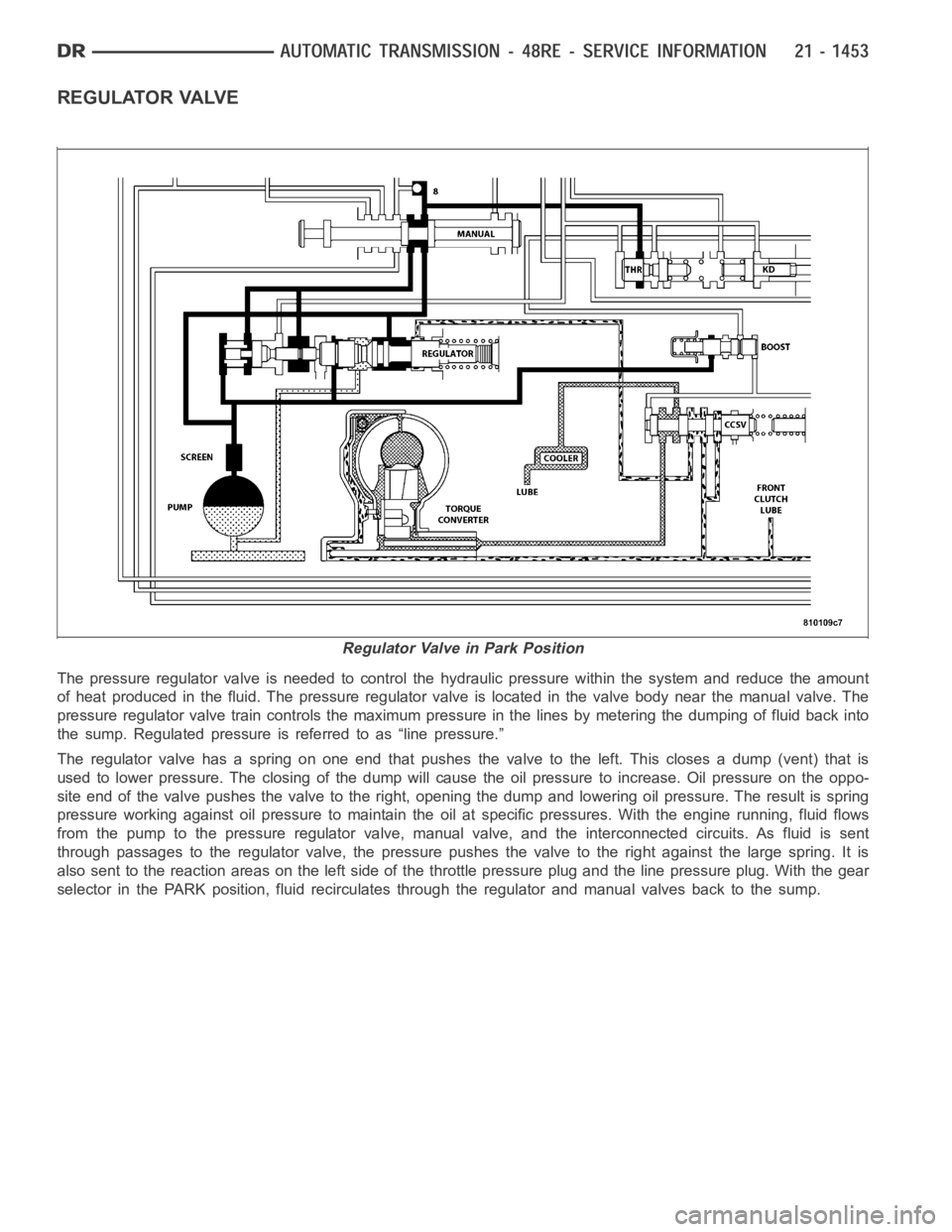
REGULATOR VALVE
The pressure regulator valve is needed to control the hydraulic pressure within the system and reduce the amount
of heat produced in the fluid. The pressure regulator valve is located in the valve body near the manual valve. The
pressure regulator valve train controls the maximum pressure in the linesby metering the dumping of fluid back into
the sump. Regulated pressure is referred to as “line pressure.”
The regulator valve has a spring on one end that pushes the valve to the left.This closes a dump (vent) that is
used to lower pressure. The closing of the dump will cause the oil pressure to increase. Oil pressure on the oppo-
site end of the valve pushes the valve to the right, opening the dump and lowering oil pressure. The result is spring
pressure working against oil pressureto maintain the oil at specific pressures. With the engine running, fluid flows
from the pump to the pressure regulator valve, manual valve, and the interconnected circuits. As fluid is sent
through passages to the regulator valve, the pressure pushes the valve to the right against the large spring. It is
also sent to the reaction areas on the left side of the throttle pressure plug and the line pressure plug. With the gear
selector in the PARK position, fluid recirculates through the regulator and manual valves back to the sump.
Regulator Valve in Park Position
Page 3991 of 5267
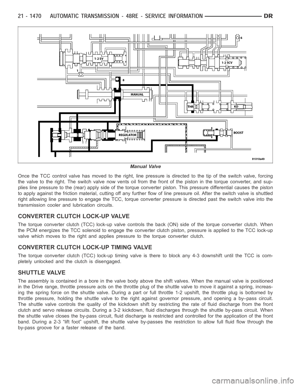
Once the TCC control valve has moved to the right, line pressure is directedto the tip of the switch valve, forcing
the valve to the right. The switch valve now vents oil from the front of the piston in the torque converter, and sup-
plies line pressure to the (rear) apply side of the torque converter piston. This pressure differential causes the piston
to apply against the friction material, cutting off any further flow of line pressure oil. After the switch valve is shuttled
right allowing line pressure to engage the TCC, torque converter pressureis directed past the switch valve into the
transmission cooler and lubrication circuits.
CONVERTER CLUTCH LOCK-UP VALVE
The torque converter clutch (TCC) lock-up valve controls the back (ON) side of the torque converter clutch. When
the PCM energizes the TCC solenoid to engage the converter clutch piston, pressure is applied to the TCC lock-up
valve which moves to the right and applies pressure to the torque converterclutch.
CONVERTER CLUTCH LOCK-UP TIMING VALVE
The torque converter clutch (TCC) lock-up timing valve is there to block any 4-3 downshift until the TCC is com-
pletely unlocked and the clutch is disengaged.
SHUTTLE VALVE
The assembly is contained in a bore in the valve body above the shift valves.When the manual valve is positioned
in the Drive range, throttle pressure acts on the throttle plug of the shuttle valve to move it against a spring, increas-
ing the spring force on the shuttle valve. During a part or full throttle 1-2upshift, the throttle plug is bottomed by
throttle pressure, holding the shuttle valve to the right against governor pressure, and opening a by–pass circuit.
The shuttle valve controls the quality of the kickdown shift by restricting the rate of fluid discharge from the front
clutch and servo release circuits. During a 3-2 kickdown, fluid discharges through the shuttle by-pass circuit. When
the shuttle valve closes the by-pass circuit, fluid discharge is restricted and controlled for the application of the front
band. During a 2-3 “lift foot” upshift, the shuttle valve by-passes the restriction to allow full fluid flow through the
by-pass groove for a faster release of the band.
Manual Valve
Page 3993 of 5267
Manual lever detent ball.
Throttle lever.
Fluid filter.
Pressure adjusting screw bracket.
Governor pressure solenoid.
Governor pressure sensor (includes transmission temperature thermistor).
Converter clutch/overdrive solenoid assembly and harness.
Governor housing gasket.
Solenoid case connector O-rings.
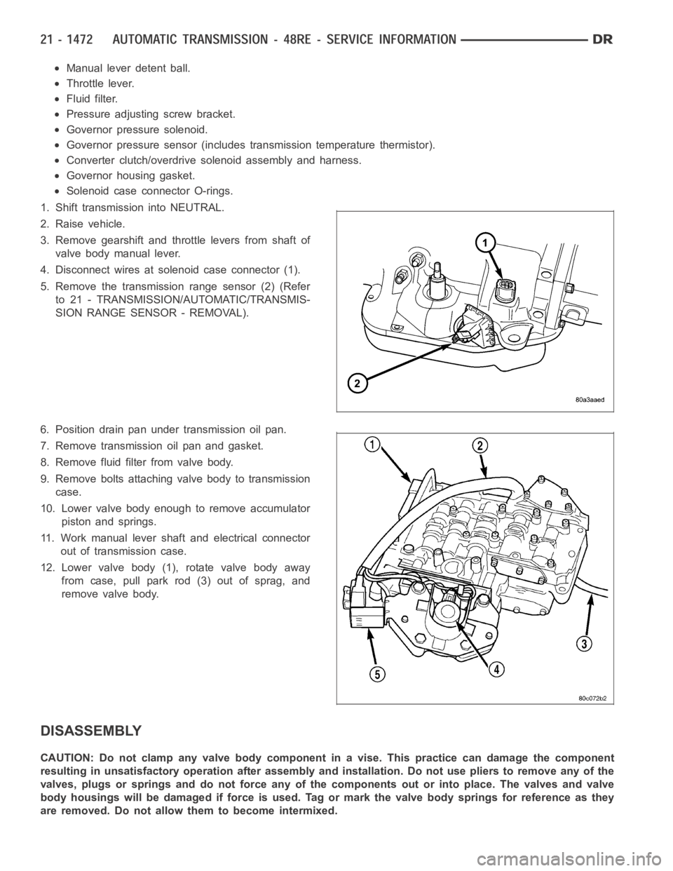
1. Shift transmission into NEUTRAL.
2. Raise vehicle.
3. Remove gearshift and throttle levers from shaft of
valve body manual lever.
4. Disconnect wires at solenoid case connector (1).
5. Remove the transmission range sensor (2) (Refer
to 21 - TRANSMISSION/AUTOMATIC/TRANSMIS-
SION RANGE SENSOR - REMOVAL).
6. Position drain pan under transmission oil pan.
7. Remove transmission oil pan and gasket.
8. Remove fluid filter from valve body.
9. Remove bolts attaching valve body to transmission
case.
10. Lower valve body enough to remove accumulator
piston and springs.
11. Work manual lever shaft and electrical connector
out of transmission case.
12. Lower valve body (1), rotate valve body away
from case, pull park rod (3) out of sprag, and
remove valve body.
DISASSEMBLY
CAUTION: Do not clamp any valve body component in a vise. This practice can damage the component
resulting in unsatisfactory operation after assembly and installation.Do not use pliers to remove any of the
valves, plugs or springs and do not force any of the components out or into place. The valves and valve
body housings will be damaged if force is used. Tag or mark the valve body springs for reference as they
are removed. Do not allow them to become intermixed.