2006 DODGE RAM SRT-10 oil pressure
[x] Cancel search: oil pressurePage 4007 of 5267
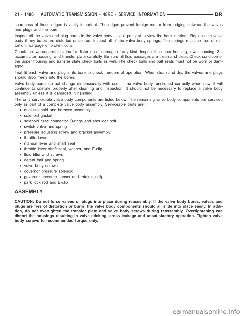
sharpness of these edges is vitally important. The edges prevent foreign matter from lodging between the valves
and plugs and the bore.
Inspect all the valve and plug bores in the valve body. Use a penlight to viewthe bore interiors. Replace the valve
body if any bores are distorted or scored. Inspect all of the valve body springs. The springs must be free of dis-
tortion, warpage or broken coils.
Check the two separator plates for distortion or damage of any kind. Inspect the upper housing, lower housing, 3-4
accumulator housing, and transfer plate carefully. Be sure all fluid passages are clean and clear. Check condition of
the upper housing and transfer plate check balls as well. The check balls and ball seats must not be worn or dam-
aged.
Trial fit each valve and plug in its bore to check freedom of operation. Whenclean and dry, the valves and plugs
shoulddropfreelyintothebores.
Valve body bores do not change dimensionally with use. If the valve body functioned correctly when new, it will
continue to operate properly after cleaning and inspection. It should notbe necessary to replace a valve body
assembly unless it is damaged in handling.
The only serviceable valve body components are listed below. The remaining valve body components are serviced
only as part of a complete valve body assembly. Serviceable parts are:
dual solenoid and harness assembly
solenoid gasket
solenoid case connector O-rings and shoulder bolt
switch valve and spring
pressure adjusting screw and bracket assembly
throttle lever
manual lever and shaft seal
throttle lever shaft seal, washer, and E-clip
fluid filter and screws
detent ball and spring
valve body screws
governor pressure solenoid
governor pressure sensor and retaining clip
park lock rod and E-clip
ASSEMBLY
CAUTION: Do not force valves or plugs into place during reassembly. If the valve body bores, valves and
plugs are free of distortion or burrs, the valve body components should allslide into place easily. In addi-
tion, do not overtighten the transfer plate and valve body screws during reassembly. Overtightening can
distort the housings resulting in valve sticking, cross leakage and unsatisfactory operation. Tighten valve
body screws to recommended torque only.
Page 5055 of 5267
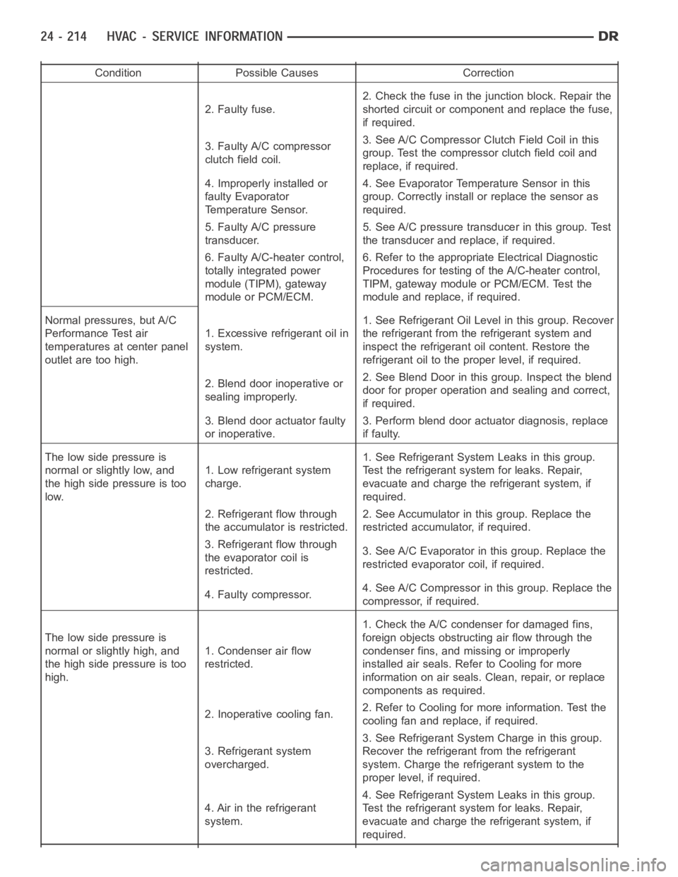
Condition Possible Causes Correction
2. Faulty fuse.2. Check the fuse in the junction block. Repair the
shorted circuit or component and replace the fuse,
if required.
3. Faulty A/C compressor
clutch field coil.3. See A/C Compressor Clutch Field Coil in this
group. Test the compressor clutch field coil and
replace, if required.
4. Improperly installed or
faulty Evaporator
Temperature Sensor.4. See Evaporator Temperature Sensor in this
group. Correctly install or replace the sensor as
required.
5. Faulty A/C pressure
transducer.5. See A/C pressure transducer in this group. Test
the transducer and replace, if required.
6. Faulty A/C-heater control,
totally integrated power
module (TIPM), gateway
module or PCM/ECM.6. Refer to the appropriate Electrical Diagnostic
Procedures for testing of the A/C-heater control,
TIPM, gateway module or PCM/ECM. Test the
module and replace, if required.
Normal pressures, but A/C
Performance Test air
temperatures at center panel
outlet are too high.1. Excessive refrigerant oil in
system.1. See Refrigerant Oil Level in this group. Recover
the refrigerant from the refrigerant system and
inspect the refrigerant oil content. Restore the
refrigerant oil to the proper level, if required.
2. Blend door inoperative or
sealing improperly.2. See Blend Door in this group. Inspect the blend
door for proper operation and sealing and correct,
if required.
3. Blend door actuator faulty
or inoperative.3. Perform blend door actuator diagnosis, replace
if faulty.
The low side pressure is
normal or slightly low, and
the high side pressure is too
low.1. Low refrigerant system
charge.1. See Refrigerant System Leaks in this group.
Test the refrigerant system for leaks. Repair,
evacuate and charge the refrigerant system, if
required.
2. Refrigerant flow through
the accumulator is restricted.2. See Accumulator in this group. Replace the
restricted accumulator, if required.
3. Refrigerant flow through
the evaporator coil is
restricted.3. See A/C Evaporator in this group. Replace the
restricted evaporator coil, if required.
4. Faulty compressor.4. See A/C Compressor in this group. Replace the
compressor, if required.
The low side pressure is
normal or slightly high, and
the high side pressure is too
high.1. Condenser air flow
restricted.1. Check the A/C condenser for damaged fins,
foreign objects obstructing air flow through the
condenser fins, and missing or improperly
installed air seals. Refer to Cooling for more
information on air seals. Clean, repair, or replace
components as required.
2. Inoperative cooling fan.2. Refer to Cooling for more information. Test the
cooling fan and replace, if required.
3. Refrigerant system
overcharged.3. See Refrigerant System Charge in this group.
Recover the refrigerant from the refrigerant
system. Charge the refrigerant system to the
proper level, if required.
4. Air in the refrigerant
system.4. See Refrigerant System Leaks in this group.
Test the refrigerant system for leaks. Repair,
evacuate and charge the refrigerant system, if
required.
Page 5057 of 5267
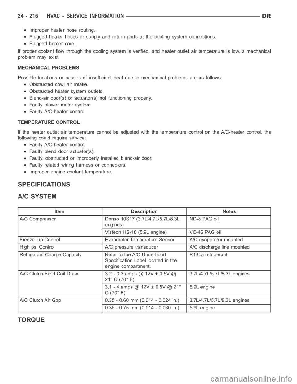
Improper heater hose routing.
Plugged heater hoses or supply and return ports at the cooling system connections.
Plugged heater core.
If proper coolant flow through the cooling system is verified, and heater outlet air temperature is low, a mechanical
problem may exist.
MECHANICAL PROBLEMS
Possible locations or causes of insufficient heat due to mechanical problems are as follows:
Obstructed cowl air intake.
Obstructed heater system outlets.
Blend-air door(s) or actuator(s) not functioning properly.
Faulty blower motor system
Faulty A/C-heater control
TEMPERATURE CONTROL
If the heater outlet air temperature cannot be adjusted with the temperature control on the A/C-heater control, the
following could require service:
Faulty A/C-heater control.
Faulty blend door actuator(s).
Faulty, obstructed or improperly installed blend-air door.
Faulty related wiring harness or connectors.
Improper engine coolant temperature.
SPECIFICATIONS
A/C SYSTEM
Item Description Notes
A/C Compressor Denso 10S17 (3.7L/4.7L/5.7L/8.3L
engines)ND-8 PAG oil
Visteon HS-18 (5.9L engine) VC-46 PAG oil
Freeze–up Control Evaporator Temperature Sensor A/C evaporator mounted
High psi Control A/C pressure transducer A/C discharge line mounted
Refrigerant Charge Capacity Refer to the A/C Underhood
Specification Label located in the
engine compartment.R134a refrigerant
A/C Clutch Field Coil Draw 3.2 - 3.3 amps @ 12V ± 0.5V @
21° C (70° F)3.7L/4.7L/5.7L/8.3L engines
3.1 - 4 amps @ 12V ± 0.5V @ 21°
C(70°F)5.9L engine
A/C Clutch Air Gap 0.35 - 0.60 mm (0.014 - 0.024 in.) 3.7L/4.7L/5.7L/8.3L engines
0.35 - 0.75 mm (0.014 - 0.030 in.) 5.9L engine
TORQUE
Page 5060 of 5267
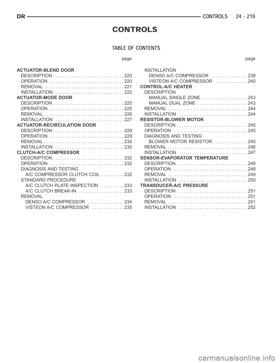
page page
ACTUATOR-BLEND DOOR
DESCRIPTION ............................... 220
OPERATION ................................. 220
REMOVAL ................................... 221
INSTALLATION .............................. 222
ACTUATOR-MODE DOOR
DESCRIPTION ............................... 225
OPERATION ................................. 225
REMOVAL ................................... 226
INSTALLATION .............................. 227
ACTUATOR-RECIRCULATION DOOR
DESCRIPTION ............................... 229
OPERATION ................................. 229
REMOVAL ................................... 230
INSTALLATION .............................. 230
CLUTCH-A/C COMPRESSOR
DESCRIPTION ............................... 232
OPERATION ................................. 232
DIAGNOSIS AND TESTING
A/C COMPRESSOR CLUTCH COIL.......... 232
STANDARD PROCEDURE
A/C CLUTCH PLATE INSPECTION.......... 233
A/C CLUTCH BREAK-IN.................... 233
REMOVAL
DENSO A/C COMPRESSOR ................ 234
VISTEON A/C COMPRESSOR .............. 235INSTALLATION
DENSO A/C COMPRESSOR................ 238
VISTEON A/C COMPRESSOR.............. 240
CONTROL-A/C HEATER
DESCRIPTION
MANUAL SINGLE ZONE .................... 243
MANUAL DUAL ZONE ...................... 243
REMOVAL ................................... 244
INSTALLATION .............................. 244
RESISTOR-BLOWER MOTOR
DESCRIPTION ............................... 245
OPERATION ................................. 245
DIAGNOSIS AND TESTING
BLOWER MOTOR RESISTOR ............... 245
REMOVAL ................................... 246
INSTALLATION .............................. 247
SENSOR-EVAPORATOR TEMPERATURE
DESCRIPTION ............................... 248
OPERATION ................................. 248
REMOVAL ................................... 249
INSTALLATION .............................. 250
TRANSDUCER-A/C PRESSURE
DESCRIPTION ............................... 251
OPERATION ................................. 251
REMOVAL ................................... 251
INSTALLATION .............................. 252
Page 5093 of 5267
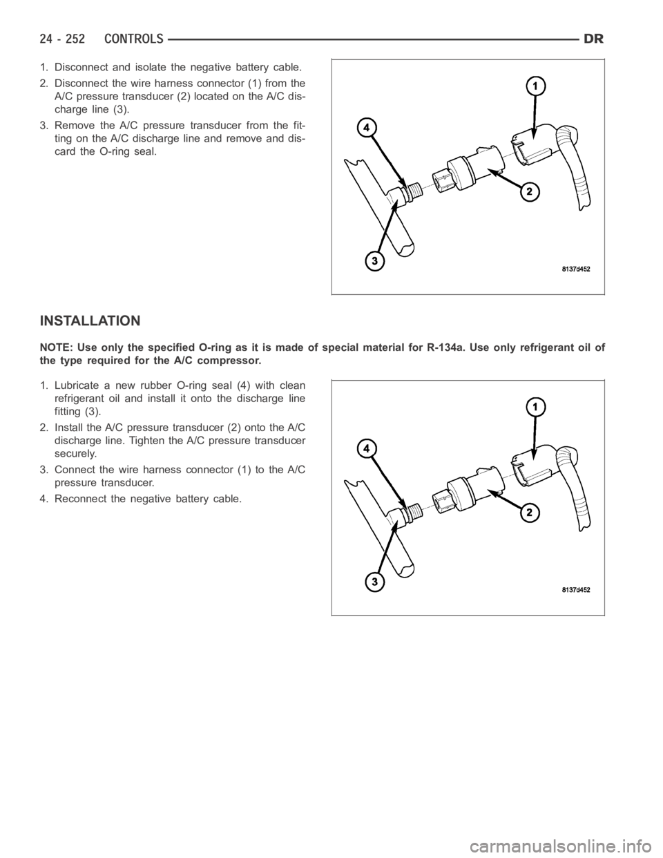
1. Disconnect and isolate the negative battery cable.
2. Disconnect the wire harness connector (1) from the
A/C pressure transducer (2) located on the A/C dis-
charge line (3).
3. Remove the A/C pressure transducer from the fit-
ting on the A/C discharge line and remove and dis-
card the O-ring seal.
INSTALLATION
NOTE:UseonlythespecifiedO-ringasitismadeofspecialmaterialforR-134a. Use only refrigerant oil of
the type required for the A/C compressor.
1. Lubricate a new rubber O-ring seal (4) with clean
refrigerant oil and install it onto the discharge line
fitting (3).
2. Install the A/C pressure transducer (2) onto the A/C
discharge line. Tighten the A/C pressure transducer
securely.
3. Connect the wire harness connector (1) to the A/C
pressure transducer.
4. Reconnect the negative battery cable.
Page 5127 of 5267
PLUMBING
DESCRIPTION
The A/C refrigerant lines and hoses are used to carry the refrigerant between the various A/C system components.
The refrigerant lines and hoses for the R-134a system on this vehicle consist of a barrier-hose design with a nylon
tube sandwiched between rubber layers. The nylon tube helps to contain theR-134a refrigerant, which has a
smaller molecular structure than R-12 refrigerant. The ends of the refrigerant lines are made from lightweight alu-
minum or steel, and commonly use braze-less fittings.
Any kinks or sharp bends in the refrigerant lines and hoses will reduce the capacity of the entire A/C system and
can reduce the flow of refrigerant in the system. The radius of all bends in the flexible hose refrigerant lines should
be at least ten times the diameter of the hose and the refrigerant lines should be routed so they are at least 80
millimeters (3 inches) away from the exhaust manifold(s) and exhaust pipe(s).
OPERATION
High pressures are produced in the refrigerant system when the A/C compressor is operating. Extreme care must
be exercised to make sure that each of the refrigerant system connections is pressure-tight and leak free. It is a
good practice to inspect all flexible hose refrigerant lines at least oncea year to make sure they are in good con-
dition and properly routed.
The refrigerant lines and hoses are coupled to other A/C system componentswith block-type fittings. An O-ring seal,
or a flat steel gasket with an integral O-ring (dual plane seal), is used to mate the refrigerant line fittings with A/C
system components to ensure the integrity of the refrigerant system.
The refrigerant lines and hoses cannot be repaired and, if faulty or damaged, they must be replaced.
WARNING
WARNING: The A/C system contains refrigerant under high pressure. Repairs should only be performed by
qualified service personnel. Severe personal injury or death may result from improper service procedures.
WARNING: Avoid breathing the refrigerant and refrigerant oil vapor or mist. Exposure may irritate the eyes,
nose, and/or throat. Wear eye protection when servicing the A/C refrigerant system. Serious eye injury can
result from direct contact with the refrigerant. If eye contact occurs, seek medical attention immediately.
WARNING: Do not expose the refrigerant to open flame. Poisonous gas is createdwhenrefrigerantis
burned. An electronic leak detector is recommended. Severe personal injury or death may result from
improper service procedures.
WARNING: If accidental system discharge occurs, ventilate the work area before resuming service. Large
amounts of refrigerant released in a closed work area will displace the oxygen and cause suffocation and
death.
WARNING: The evaporation rate of R-134a refrigerant at average temperature and altitude is extremely high.
As a result, anything that comes in contact with the refrigerant will freeze. Always protect the skin or del-
icate objects from direct contact with the refrigerant.
WARNING: The R-134a service equipment or the vehicle refrigerant system should not be pressure tested or
leak tested with compressed air. Some mixtures of air and R-134a have been shown to be combustible at
elevated pressures. These mixtures are potentially dangerous, and may result in fire or explosion causing
property damage, personal injury or death.
Page 5128 of 5267
WARNING: The engine cooling system is designed to develop internal pressures up to 145 kilopascals (21
pounds per square inch). Do not remove or loosen the coolant pressure cap, cylinder block drain plugs,
radiator drain, radiator hoses, heater hoses, or hose clamps while the engine cooling system is hot and
under pressure. Allow the vehicle to cool for a minimum of 15 minutes beforeopening the cooling system
for service. Failure to observe this warning can result in serious burns from the heated engine coolant.
CAUTION
CAUTION: Never add R-12 to a refrigerant system designed to use R-134a. Do not use R-12 equipment or
parts on an R-134a A/C system. These refrigerants are not compatible and damage to the A/C system will
result.
CAUTION: Never use R-12 refrigerant oil in a A/C system designed to use R-134a refrigerant oil. These
refrigerant oils are not compatible and damage to the A/C system will result.
CAUTION: The use of A/C system sealers may result in damage to A/C refrigerant recovery/evacuation/re-
charging equipment and/or A/C system. Many federal, state/provincial and local regulations prohibit the
recharge of A/C systems with known leaks. DaimlerChrysler recommends thedetection of A/C system leaks
through the use of approved leak detectors and fluorescent leak detectiondyes. Vehicles found with A/C
system sealers should be treated as contaminated and replacement of the entire A/C refrigerant system is
recommended. A/C systems found to be contaminated with A/C system sealers, A/C stop-leak products or
seal conditioners voids the warranty for the A/C system.
CAUTION: Recover the refrigerant before opening any fitting or connection. Open the fittings with caution,
even after the system has been discharged. Never open or loosen a connection before recovering the refrig-
erant.
CAUTION: If equipped, do not remove the secondary retention clip from any spring-lock coupler connection
while the refrigerant system is under pressure. Recover the refrigerant before removing the secondary
retention clip. Open the fittings with caution, even after the system has been discharged. Never open or
loosen a connection before recovering the refrigerant.
CAUTION: The internal parts of the A/C system will remain stable as long as moisture-free refrigerant and
refrigerant oil is used. Abnormal amounts of dirt, moisture or air can upset the chemical stability. This may
cause operational troubles or even serious damage if present in more than very small quantities. Before
disconnecting a component, clean the outside of the fittings thoroughly to prevent contamination from
entering the refrigerant system. Keep service tools and the work area clean. Do not open the refrigerant
system or uncap a replacement component until you are ready to service the system. Immediately after
disconnecting a component from the refrigerant system, seal the open fittings with a cap or plug. This will
prevent contamination from entering the A/C system.
CAUTION: Refrigerant oil will absorb moisture from the atmosphere if leftuncapped. Do not open a con-
tainer of refrigerant oil until you are ready to use it. Replace the cap on the oil container immediately after
using. Store refrigerant oil only in a clean, airtight, and moisture-freecontainer.
CAUTION: Do not overcharge the refrigerant system. Overcharging will cause excessive compressor head
pressure and can cause compressor noise and A/C system failure.
Page 5129 of 5267
DIAGNOSIS AND TESTING
REFRIGERANT SYSTEM LEAKS
WARNING: R-134a service equipment or vehicle A/C system should not be pressure tested or leak tested
with compressed air. Mixture of air and R-134a can be combustible at elevated pressures. These mixtures
are potentially dangerous and may result in fire or explosion causing property damage, personal injury or
death.
Avoid breathing A/C refrigerant and lubricant vapor or mist. Exposure mayirritate eyes, nose and throat.
Use only approved service equipment meeting SAE requirements to discharge R-134a system. If accidental
system discharge occurs, ventilate work area before resuming service.
NOTE: If the A/C refrigerant system charge is empty or low, a leak in the A/C system is likely. Visually
inspect all A/C lines, fittings and components for an oily residue. Oil residue can be an indicator of an A/C
system leak location.
NOTE: The only way to correctly determine if the refrigerant system is fully charged with R-134a is to com-
pletely evacuate and recharge the A/C system.
Connect a suitable manifold gauge setand determine if the static A/C system pressure is above or below 345 kPa
(50 psi) (refer to 24 - HEATING & AIR CONDITIONING/PLUMBING - STANDARD PROCEDURE - REFRIGERANT
SYSTEM SERVICE EQUIPMENT). If less than 345 kPa (50 psi), proceed to SYSTEMEMPTY . If greater than 345
kPa (50 psi), go to SYSTEM LOW .
SYSTEM EMPTY
1. Evacuate the refrigerant system to the lowest degree of vacuum possible(approximately -88 kPa (- 26 in. Hg) or
greater vacuum) (Refer to 24 - HEATING & AIR CONDITIONING/PLUMBING - STANDARD PROCEDURE -
REFRIGERANT SYSTEM EVACUATE). Determine if the system holds a vacuum for 15 minutes. If vacuum is
held, a leak is probably not present. If system will not maintain vacuum level, proceed to Step 2.
2. Prepare and dispense 0.284 kilograms (10 ounces) of R-134a refrigerantinto the evacuated refrigerant system
(Refer to 24 - HEATING & AIR CONDITIONING/PLUMBING - STANDARD PROCEDURE - REFRIGERANT SYS-
TEM CHARGE) and proceed to Step 1 of the System Low procedure.
SYSTEM LOW
1. Position the vehicle in a wind-freework area. This will aid in detectingsmall leaks.
2. Operate the heating-A/C system with the engine at idle under the following conditions for at least five minutes.
Doors or windows open
Transmission in Park or Neutral with the parking brake set (depending on application)
A/C-heater controls set to outside air, full cool, panel mode, high blowerand with A/C compressor engaged
CAUTION: A leak detector only designed for R-12 refrigerant will not detect leaks in an R-134a refrigerant
system.
3. Shut the vehicle Off and wait 2-7 minutes. Then use an electronic leak detector that is designed to detect R-134a
refrigerant and search for leaks. Fittings, lines or components that appear to be oily usually indicate a refrigerant
leak. To inspect the A/C evaporator for leaks, insert the leak detector probe into the drain tube opening or an air
outlet. A dye for R-134a is available to aid in leak detection. Use only DaimlerChrysler approved refrigerant dye.