2006 DODGE RAM SRT-10 oil pressure
[x] Cancel search: oil pressurePage 3016 of 5267
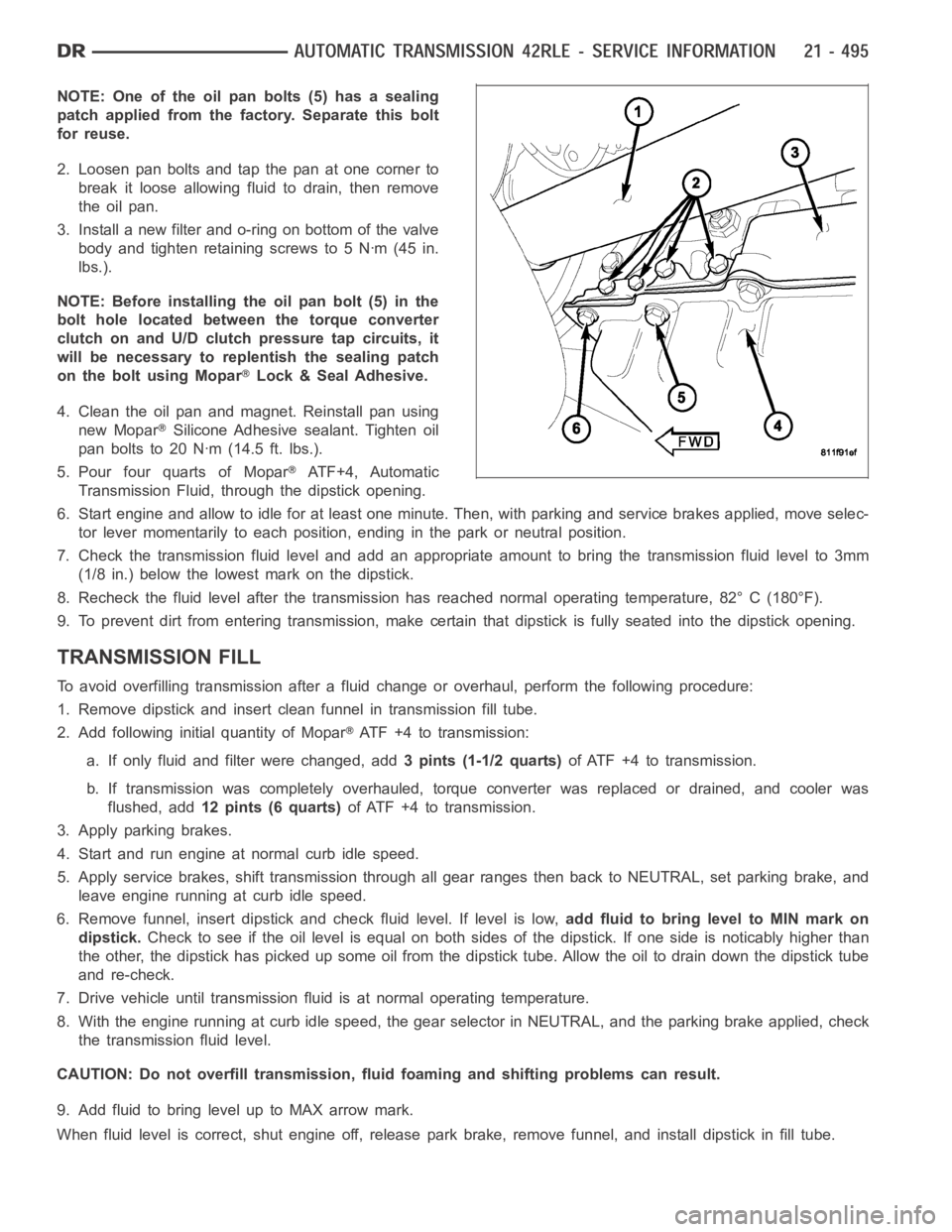
NOTE: One of the oil pan bolts (5) has a sealing
patch applied from the factory. Separate this bolt
for reuse.
2. Loosen pan bolts and tap the pan at one corner to
break it loose allowing fluid to drain, then remove
the oil pan.
3. Install a new filter and o-ring on bottom of the valve
body and tighten retaining screws to 5 Nꞏm (45 in.
lbs.).
NOTE: Before installing the oil pan bolt (5) in the
bolt hole located between the torque converter
clutch on and U/D clutch pressure tap circuits, it
will be necessary to replentish the sealing patch
on the bolt using Mopar
Lock & Seal Adhesive.
4. Clean the oil pan and magnet. Reinstall pan using
new Mopar
Silicone Adhesive sealant. Tighten oil
pan bolts to 20 Nꞏm (14.5 ft. lbs.).
5. Pour four quarts of Mopar
AT F + 4 , A u t o m a t i c
Transmission Fluid, through the dipstick opening.
6. Start engine and allow to idle for at least one minute. Then, with parkingand service brakes applied, move selec-
tor lever momentarily to each position, ending in the park or neutral position.
7. Check the transmission fluid level and add an appropriate amount to bring the transmission fluid level to 3mm
(1/8 in.) below the lowest mark on the dipstick.
8. Recheck the fluid level after the transmission has reached normal operating temperature, 82° C (180°F).
9. To prevent dirt from entering transmission, make certain that dipstickis fully seated into the dipstick opening.
TRANSMISSION FILL
To avoid overfilling transmission after a fluid change or overhaul, perform the following procedure:
1. Remove dipstick and insert clean funnel in transmission fill tube.
2. Add following initial quantity of Mopar
ATF+4totransmission:
a. If only fluid and filter were changed, add3 pints (1-1/2 quarts)of ATF +4 to transmission.
b. If transmission was completely overhauled, torque converter was replaced or drained, and cooler was
flushed, add12 pints (6 quarts)of ATF +4 to transmission.
3. Apply parking brakes.
4. Start and run engine at normal curb idle speed.
5. Apply service brakes, shift transmission through all gear ranges then back to NEUTRAL, set parking brake, and
leave engine running at curb idle speed.
6. Remove funnel, insert dipstick andcheck fluid level. If level is low,add fluid to bring level to MIN mark on
dipstick.Check to see if the oil level is equal on both sides of the dipstick. If one side is noticably higher than
the other, the dipstick has picked up some oil from the dipstick tube. Allowthe oil to drain down the dipstick tube
and re-check.
7. Drive vehicle until transmission fluid is at normal operating temperature.
8. With the engine running at curb idle speed, the gear selector in NEUTRAL,and the parking brake applied, check
the transmission fluid level.
CAUTION: Do not overfill transmission, fluid foaming and shifting problems can result.
9. Add fluid to bring level up to MAX arrow mark.
When fluid level is correct, shut engine off, release park brake, remove funnel, and install dipstick in fill tube.
Page 3046 of 5267
SENSOR-VARIABLE LINE PRESSURE
DESCRIPTION
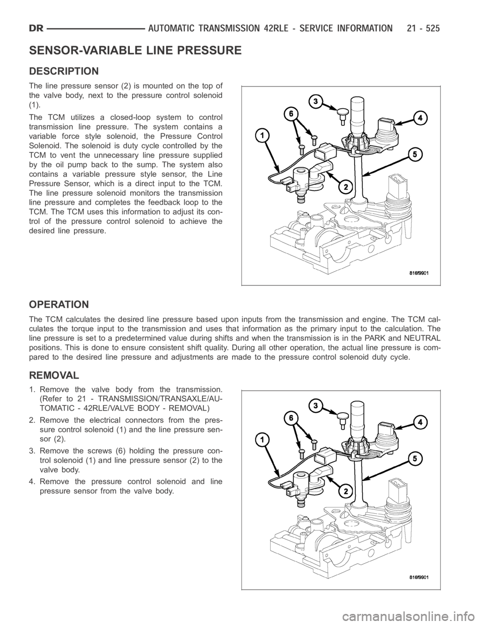
The line pressure sensor (2) is mounted on the top of
the valve body, next to the pressure control solenoid
(1).
The TCM utilizes a closed-loop system to control
transmission line pressure. The system contains a
variable force style solenoid, the Pressure Control
Solenoid. The solenoid is duty cycle controlled by the
TCM to vent the unnecessary line pressure supplied
by the oil pump back to the sump. The system also
contains a variable pressure style sensor, the Line
Pressure Sensor, which is a direct input to the TCM.
The line pressure solenoid monitors the transmission
line pressure and completes the feedback loop to the
TCM. The TCM uses this information to adjust its con-
trol of the pressure control solenoid to achieve the
desired line pressure.
OPERATION
The TCM calculates the desired line pressure based upon inputs from the transmission and engine. The TCM cal-
culates the torque input to the transmission and uses that information as the primary input to the calculation. The
line pressure is set to a predetermined value during shifts and when the transmission is in the PARK and NEUTRAL
positions. This is done to ensure consistent shift quality. During all other operation, the actual line pressure is com-
pared to the desired line pressure and adjustments are made to the pressurecontrol solenoid duty cycle.
REMOVAL
1. Remove the valve body from the transmission.
(Refer to 21 - TRANSMISSION/TRANSAXLE/AU-
TOMATIC - 42RLE/VALVE BODY - REMOVAL)
2. Remove the electrical connectors from the pres-
sure control solenoid (1) and the line pressure sen-
sor (2).
3. Remove the screws (6) holding the pressure con-
trol solenoid (1) and line pressure sensor (2) to the
valve body.
4. Remove the pressure control solenoid and line
pressure sensor from the valve body.
Page 3055 of 5267

SOLENOID-PRESSURE CONTROL
DESCRIPTION
Thepressurecontrolsolenoid(1)ismountedonthe
top of the valve body, next to the line pressure sensor
(2).
The TCM utilizes a closed-loop system to control
transmission line pressure. The system contains a
variable force style solenoid, the Pressure Control
Solenoid. The solenoid is duty cycle controlled by the
TCM to vent the unnecessary line pressure supplied
by the oil pump back to the sump. The system also
contains a variable pressure style sensor, the Line
Pressure Sensor, which is a direct input to the TCM.
The line pressure solenoid monitors the transmission
line pressure and completes the feedback loop to the
TCM. The TCM uses this information to adjust its con-
trol of the pressure control solenoid to achieve the
desired line pressure.
OPERATION
The pressure control solenoid (PCS) is a variable force (VFS) style solenoid. A VFS solenoid is an electro-hydraulic
actuator, combining a solenoid and a regulating valve.
The transmission control module varies the current for the PCS, which variesthepressureinthelinepressure
hydraulic circuit. When the current (duty cycle) of the PCS is low, the pressure in the circuit is higher. At 0 current
(0% duty cycle), the pressure is at the maximum value. Conversely, when thecurrent is maximized (100% duty
cycle), the pressure in the circuit is at the lowest possible value.
REMOVAL
1. Remove the valve body from the transmission.
(Refer to 21 - TRANSMISSION/TRANSAXLE/AU-
TOMATIC - 42RLE/VALVE BODY - REMOVAL)
2. Remove the electrical connectors from the pres-
sure control solenoid (1) and the line pressure sen-
sor (2).
3. Remove the screws (6) holding the pressure con-
trol solenoid (1) and line pressure sensor (2) to the
valve body.
4. Remove the pressure control solenoid and line
pressure sensor from the valve body.
Page 3058 of 5267
SOLENOID
DESCRIPTION
The typical electrical solenoid used in automotive applications is a linear actuator. It is a device that produces
motion in a straight line. This straight line motion can be either forward or backward in direction, and short or long
distance.
A solenoid is an electromechanical device that uses a magnetic force to perform work. It consists of a coil of wire,
wrapped around a magnetic core made from steel or iron, and a spring loaded,movable plunger, which performs
the work, or straight line motion.
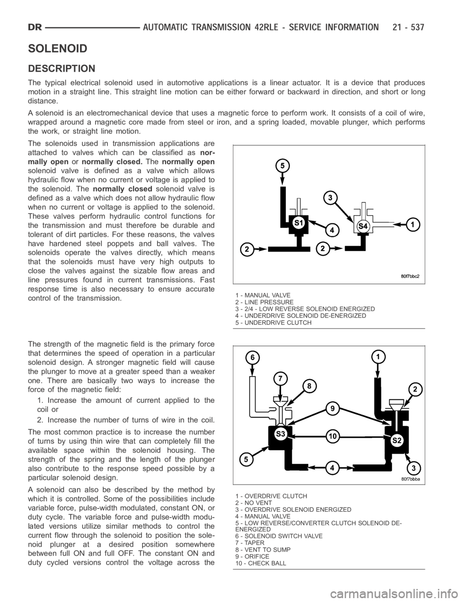
The solenoids used in transmission applications are
attached to valves which can be classified asnor-
mally openornormally closed.Thenormally open
solenoid valve is defined as a valve which allows
hydraulic flow when no current or voltage is applied to
the solenoid. Thenormally closedsolenoid valve is
defined as a valve which does not allow hydraulic flow
when no current or voltage is applied to the solenoid.
These valves perform hydraulic control functions for
the transmission and must therefore be durable and
tolerant of dirt particles. For these reasons, the valves
have hardened steel poppets and ball valves. The
solenoids operate the valves directly, which means
that the solenoids must have very high outputs to
close the valves against the sizable flow areas and
line pressures found in current transmissions. Fast
response time is also necessary to ensure accurate
control of the transmission.
The strength of the magnetic field is the primary force
that determines the speed of operation in a particular
solenoid design. A stronger magnetic field will cause
the plunger to move at a greater speed than a weaker
one. There are basically two ways to increase the
force of the magnetic field:
1. Increase the amount of current applied to the
coil or
2. Increase the number of turns of wire in the coil.
The most common practice is to increase the number
of turns by using thin wire that can completely fill the
available space within the solenoid housing. The
strength of the spring and the length of the plunger
also contribute to the response speed possible by a
particular solenoid design.
A solenoid can also be described by the method by
which it is controlled. Some of the possibilities include
variable force, pulse-width modulated, constant ON, or
duty cycle. The variable force and pulse-width modu-
lated versions utilize similar methods to control the
current flow through the solenoid to position the sole-
noid plunger at a desired position somewhere
between full ON and full OFF. The constant ON and
duty cycled versions control the voltage across the
1 - MANUAL VALVE
2 - LINE PRESSURE
3 - 2/4 - LOW REVERSE SOLENOID ENERGIZED
4 - UNDERDRIVE SOLENOID DE-ENERGIZED
5 - UNDERDRIVE CLUTCH
1-OVERDRIVECLUTCH
2 - NO VENT
3 - OVERDRIVE SOLENOID ENERGIZED
4 - MANUAL VALVE
5 - LOW REVERSE/CONVERTER CLUTCH SOLENOID DE-
ENERGIZED
6-SOLENOIDSWITCHVALVE
7 - TAPER
8 - VENT TO SUMP
9 - ORIFICE
10 - CHECK BALL
Page 3059 of 5267
solenoid to allow either full flow or noflow through the solenoid’s valve.
OPERATION
When an electrical current is applied to the solenoid coil, a magnetic field is created which produces an attraction
to the plunger, causing the plunger to move and work against the spring pressure and the load applied by the fluid
the valve is controlling. The plunger is normally directly attached to thevalve which it is to operate. When the cur-
rent is removed from the coil, the attraction is removed and the plunger will return to its original position due to
spring pressure.
The plunger is made of a conductive material and accomplishes this movement by providing a path for the magnetic
field to flow. By keeping the air gap between the plunger and the coil to the minimum necessary to allow free move-
ment of the plunger, the magnetic field is maximized.
Page 3068 of 5267
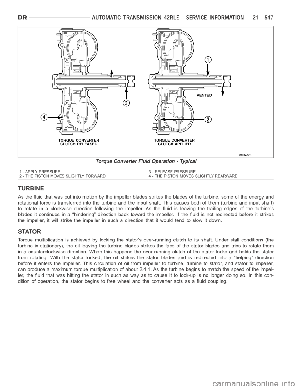
TURBINE
As the fluid that was put into motion bythe impeller blades strikes the blades of the turbine, some of the energy and
rotational force is transferred into the turbine and the input shaft. Thiscauses both of them (turbine and input shaft)
to rotate in a clockwise direction following the impeller. As the fluid is leaving the trailing edges of the turbine’s
blades it continues in a “hindering” direction back toward the impeller. If the fluid is not redirected before it strikes
the impeller, it will strike the impeller in such a direction that it would tend to slow it down.
STATOR
Torque multiplication is achieved by locking the stator’s over-running clutch to its shaft. Under stall conditions (the
turbine is stationary), the oil leaving the turbine blades strikes the face of the stator blades and tries to rotate them
in a counterclockwise direction. When this happens the over-running clutch of the stator locks and holds the stator
from rotating. With the stator locked, the oil strikes the stator blades and is redirected into a “helping” direction
before it enters the impeller. This circulation of oil from impeller to turbine, turbine to stator, and stator to impeller,
can produce a maximum torque multiplicationofabout2.4:1.Astheturbinebegins to match the speed of the impel-
ler, the fluid that was hitting the stator in such as way as to cause it to lock-up is no longer doing so. In this con-
dition of operation, the stator begins to free wheel and the converter actsas a fluid coupling.
Torque Converter Fluid Operation - Typical
1 - APPLY PRESSURE 3 - RELEASE PRESSURE
2 - THE PISTON MOVES SLIGHTLY FORWARD 4 - THE PISTON MOVES SLIGHTLY REARWARD
Page 3080 of 5267
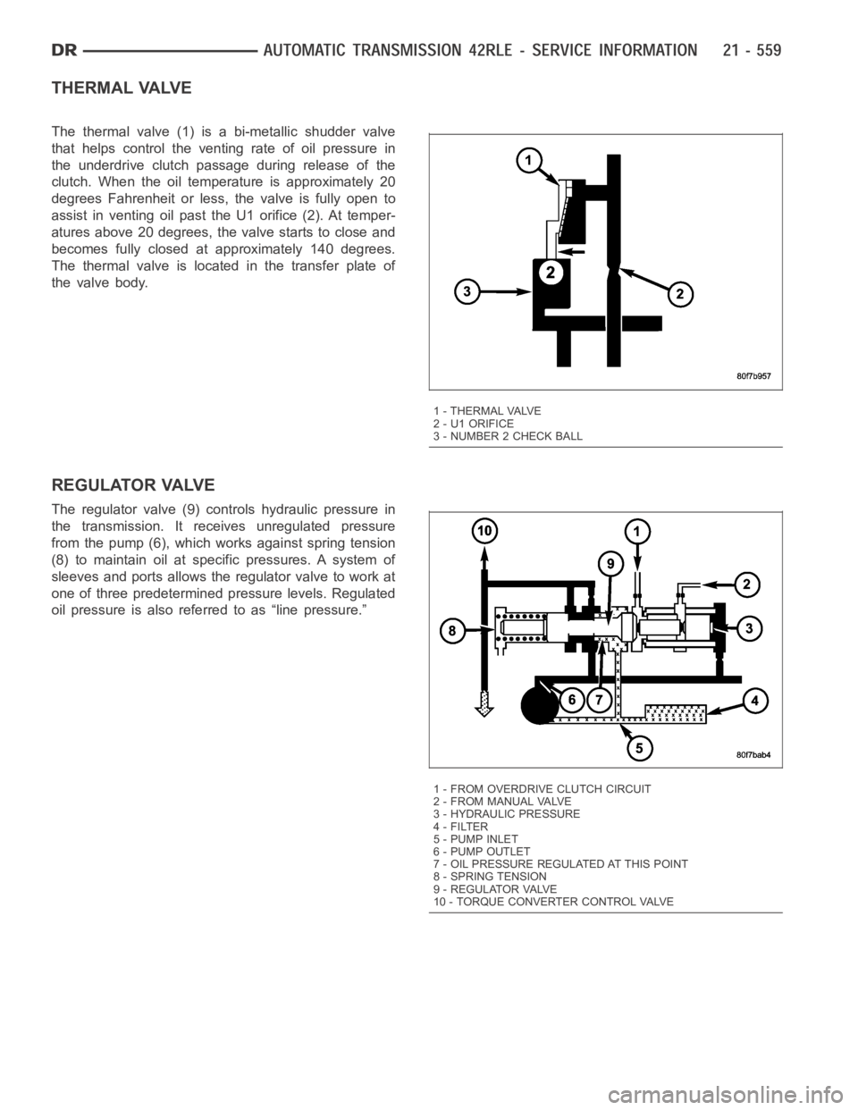
THERMAL VALVE
The thermal valve (1) is a bi-metallic shudder valve
that helps control the venting rate of oil pressure in
the underdrive clutch passage during release of the
clutch. When the oil temperature is approximately 20
degrees Fahrenheit or less, the valve is fully open to
assist in venting oil past the U1 orifice (2). At temper-
atures above 20 degrees, the valve starts to close and
becomes fully closed at approximately 140 degrees.
The thermal valve is located in the transfer plate of
the valve body.
REGULATOR VALVE
The regulator valve (9) controls hydraulic pressure in
the transmission. It receives unregulated pressure
from the pump (6), which works against spring tension
(8) to maintain oil at specific pressures. A system of
sleeves and ports allows the regulator valve to work at
one of three predetermined pressure levels. Regulated
oil pressure is also referred to as “line pressure.”
1 - THERMAL VALVE
2 - U1 ORIFICE
3 - NUMBER 2 CHECK BALL
1 - FROM OVERDRIVE CLUTCH CIRCUIT
2 - FROM MANUAL VALVE
3 - HYDRAULIC PRESSURE
4-FILTER
5-PUMPINLET
6 - PUMP OUTLET
7 - OIL PRESSURE REGULATED AT THIS POINT
8 - SPRING TENSION
9 - REGULATOR VALVE
10 - TORQUE CONVERTER CONTROL VALVE
Page 3084 of 5267
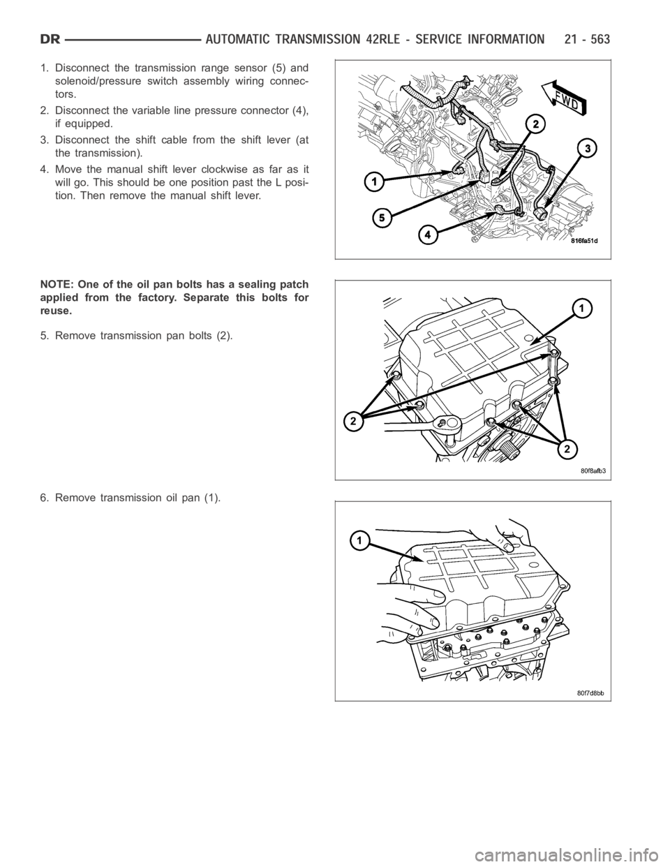
1. Disconnect the transmission range sensor (5) and
solenoid/pressure switchassembly wiring connec-
tors.
2. Disconnect the variable line pressure connector (4),
if equipped.
3. Disconnect the shift cable from the shift lever (at
the transmission).
4. Move the manual shift lever clockwise as far as it
will go. This should be one position past the L posi-
tion. Then remove the manual shift lever.
NOTE: One of the oil pan bolts has a sealing patch
applied from the factory. Separate this bolts for
reuse.
5. Remove transmission pan bolts (2).
6. Remove transmission oil pan (1).