2006 DODGE RAM SRT-10 oil pressure
[x] Cancel search: oil pressurePage 1907 of 5267
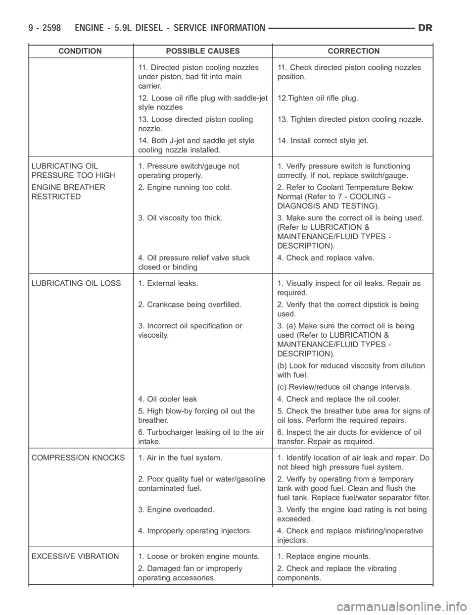
CONDITION POSSIBLE CAUSES CORRECTION
11. Directed piston cooling nozzles
under piston, bad fit into main
carrier.11. Check directed piston cooling nozzles
position.
12. Loose oil rifle plug with saddle-jet
style nozzles12.Tighten oil rifle plug.
13. Loose directed piston cooling
nozzle.13. Tighten directed piston cooling nozzle.
14. Both J-jet and saddle jet style
cooling nozzle installed.14. Install correct style jet.
LUBRICATING OIL
PRESSURE TOO HIGH1. Pressure switch/gauge not
operating properly.1. Verify pressure switch is functioning
correctly. If not, replace switch/gauge.
ENGINE BREATHER
RESTRICTED2. Engine running too cold. 2. Refer to Coolant Temperature Below
Normal (Refer to 7 - COOLING -
DIAGNOSIS AND TESTING).
3. Oil viscosity too thick. 3. Make sure the correct oil is being used.
(Refer to LUBRICATION &
MAINTENANCE/FLUID TYPES -
DESCRIPTION).
4. Oil pressure relief valve stuck
closed or binding4. Check and replace valve.
LUBRICATING OIL LOSS 1. External leaks. 1. Visually inspect for oil leaks.Repair as
required.
2. Crankcase being overfilled. 2. Verify that the correct dipstick is being
used.
3. Incorrect oil specification or
viscosity.3. (a) Make sure the correct oil is being
used (Refer to LUBRICATION &
MAINTENANCE/FLUID TYPES -
DESCRIPTION).
(b) Look for reduced viscosity from dilution
with fuel.
(c) Review/reduce oil change intervals.
4. Oil cooler leak 4. Check and replace the oil cooler.
5. High blow-by forcing oil out the
breather.5. Check the breather tube area for signs of
oil loss. Perform the required repairs.
6. Turbocharger leaking oil to the air
intake.6. Inspect the air ducts for evidence of oil
transfer. Repair as required.
COMPRESSION KNOCKS 1. Air in the fuel system. 1. Identify location of air leak and repair. Do
not bleed high pressure fuel system.
2. Poor quality fuel or water/gasoline
contaminated fuel.2. Verify by operating from a temporary
tank with good fuel. Clean and flush the
fuel tank. Replace fuel/water separator filter.
3. Engine overloaded. 3. Verify the engine load rating is not being
exceeded.
4. Improperly operating injectors. 4. Check and replace misfiring/inoperative
injectors.
EXCESSIVE VIBRATION 1. Loose or broken engine mounts. 1. Replace engine mounts.
2. Damaged fan or improperly
operating accessories.2. Check and replace the vibrating
components.
Page 1911 of 5267
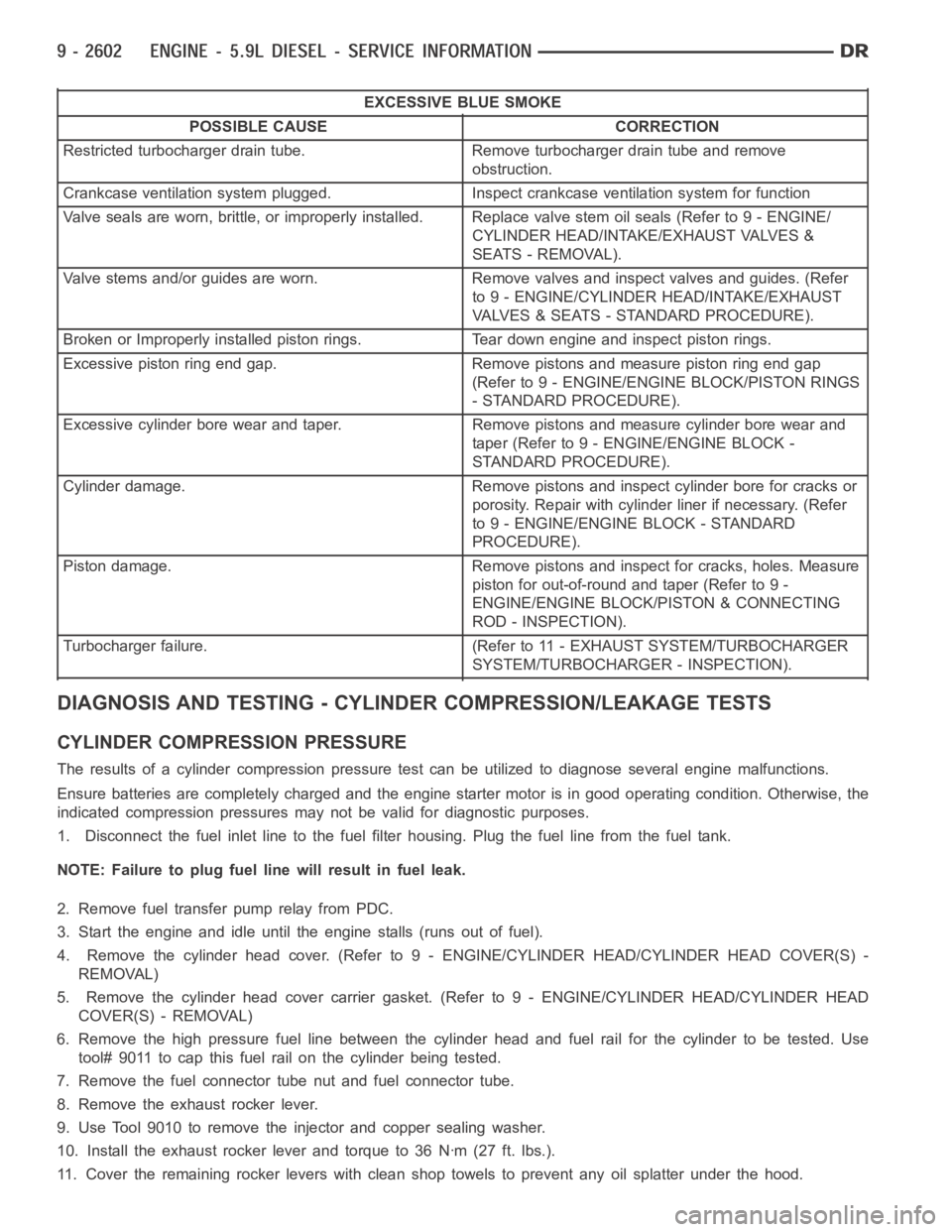
EXCESSIVE BLUE SMOKE
POSSIBLE CAUSE CORRECTION
Restricted turbocharger drain tube. Remove turbocharger drain tube and remove
obstruction.
Crankcase ventilation system plugged. Inspect crankcase ventilation system for function
Valve seals are worn, brittle, or improperly installed. Replace valve stemoilseals(Referto9-ENGINE/
CYLINDER HEAD/INTAKE/EXHAUST VALVES &
SEATS - REMOVAL).
Valve stems and/or guides are worn. Remove valves and inspect valves and guides. (Refer
to 9 - ENGINE/CYLINDER HEAD/INTAKE/EXHAUST
VALVES & SEATS - STANDARD PROCEDURE).
Broken or Improperly installed piston rings. Tear down engine and inspectpiston rings.
Excessive piston ring end gap. Remove pistons and measure piston ring end gap
(Refer to 9 - ENGINE/ENGINE BLOCK/PISTON RINGS
- STANDARD PROCEDURE).
Excessive cylinder bore wear and taper. Remove pistons and measure cylinder bore wear and
taper (Refer to 9 - ENGINE/ENGINE BLOCK -
STANDARD PROCEDURE).
Cylinder damage. Remove pistons and inspect cylinder bore for cracks or
porosity. Repair with cylinder liner if necessary. (Refer
to 9 - ENGINE/ENGINE BLOCK - STANDARD
PROCEDURE).
Piston damage. Remove pistons and inspect for cracks, holes. Measure
piston for out-of-round and taper (Refer to 9 -
ENGINE/ENGINE BLOCK/PISTON & CONNECTING
ROD - INSPECTION).
Turbocharger failure. (Refer to 11 - EXHAUST SYSTEM/TURBOCHARGER
SYSTEM/TURBOCHARGER - INSPECTION).
DIAGNOSIS AND TESTING - CYLINDER COMPRESSION/LEAKAGE TESTS
CYLINDER COMPRESSION PRESSURE
The results of a cylinder compressionpressure test can be utilized to diagnose several engine malfunctions.
Ensure batteries are completely charged and the engine starter motor is ingood operating condition. Otherwise, the
indicated compression pressures may not be valid for diagnostic purposes.
1. Disconnect the fuel inlet line to the fuel filter housing. Plug the fuel line from the fuel tank.
NOTE: Failure to plug fuel line will result in fuel leak.
2. Remove fuel transfer pump relay from PDC.
3. Start the engine and idle until the engine stalls (runs out of fuel).
4. Remove the cylinder head cover. (Refer to 9 - ENGINE/CYLINDER HEAD/CYLINDER HEAD COVER(S) -
REMOVAL)
5. Remove the cylinder head cover carrier gasket. (Refer to 9 - ENGINE/CYLINDER HEAD/CYLINDER HEAD
COVER(S) - REMOVAL)
6. Remove the high pressure fuel line between the cylinder head and fuel rail for the cylinder to be tested. Use
tool# 9011 to cap this fuel rail on the cylinder being tested.
7. Remove the fuel connector tube nut and fuel connector tube.
8. Remove the exhaust rocker lever.
9. Use Tool 9010 to remove the injector and copper sealing washer.
10. Install the exhaust rocker lever and torque to 36 Nꞏm (27 ft. lbs.).
11. Cover the remaining rocker levers with clean shop towels to prevent anyoil splatter under the hood.
Page 1914 of 5267
3. Place a shop towel around the fuel injectors to catch any fluid that may possibly be under pressure in the cyl-
inder head. Remove the fuel injectors (Refer to 14 - FUEL SYSTEM/FUEL INJECTION/FUEL INJECTOR -
REMOVAL).
4. With all injectors removed, rotatethe crankshaft using the crankshaftbarring tool (PN 7471–B).
5. Identify the fluid in the cylinders (coolant, fuel, oil, etc.).
6. Be sure all fluid has been removed from the cylinders.
7. Repair engine or components as necessary to prevent this problem from occurring again.
8. Squirt a small amount of engine oil into the cylinders to lubricate the walls. This will prevent damage on restart.
9. Install fuel injectors (Refer to 14 - FUEL SYSTEM/FUEL INJECTION/FUEL INJECTOR - INSTALLATION).
10. Drain engine oil. Remove and discard the oil filter (Refer to 9 - ENGINE/LUBRICATION/OIL FILTER -
REMOVAL).
11. Installthedrainplug.Tightentheplugto50Nꞏm(37ft.lbs.)torque.
12. Install a new oil filter (Refer to 9 - ENGINE/LUBRICATION/OIL FILTER - INSTALLATION).
13. Fill engine crankcase with the specified amount and grade of oil (Referto LUBRICATION & MAINTENANCE/
FLUID TYPES - SPECIFICATIONS).
14. Connect the negative cable(s) to the battery.
15. Start the engine and check for any leaks.
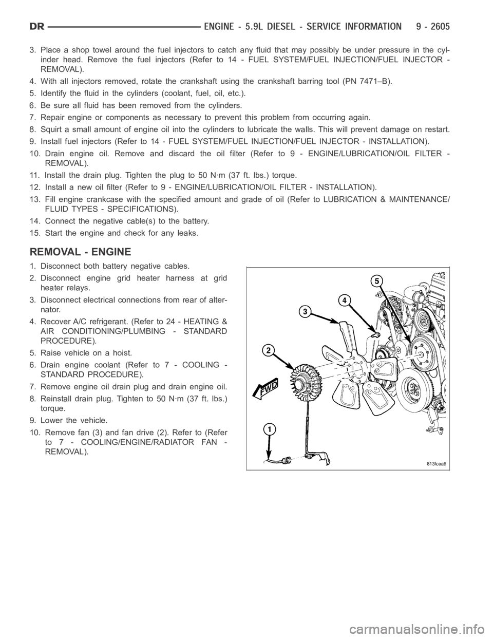
REMOVAL - ENGINE
1. Disconnect both battery negative cables.
2. Disconnect engine grid heater harness at grid
heater relays.
3. Disconnect electrical connections from rear of alter-
nator.
4. Recover A/C refrigerant. (Refer to 24 - HEATING &
AIR CONDITIONING/PLUMBING - STANDARD
PROCEDURE).
5. Raise vehicle on a hoist.
6. Drain engine coolant (Refer to 7 - COOLING -
STANDARD PROCEDURE).
7. Remove engine oil drain plug and drain engine oil.
8. Reinstall drain plug. Tighten to 50 Nꞏm (37 ft. lbs.)
torque.
9. Lower the vehicle.
10. Remove fan (3) and fan drive (2). Refer to (Refer
to 7 - COOLING/ENGINE/RADIATOR FAN -
REMOVAL).
Page 1925 of 5267
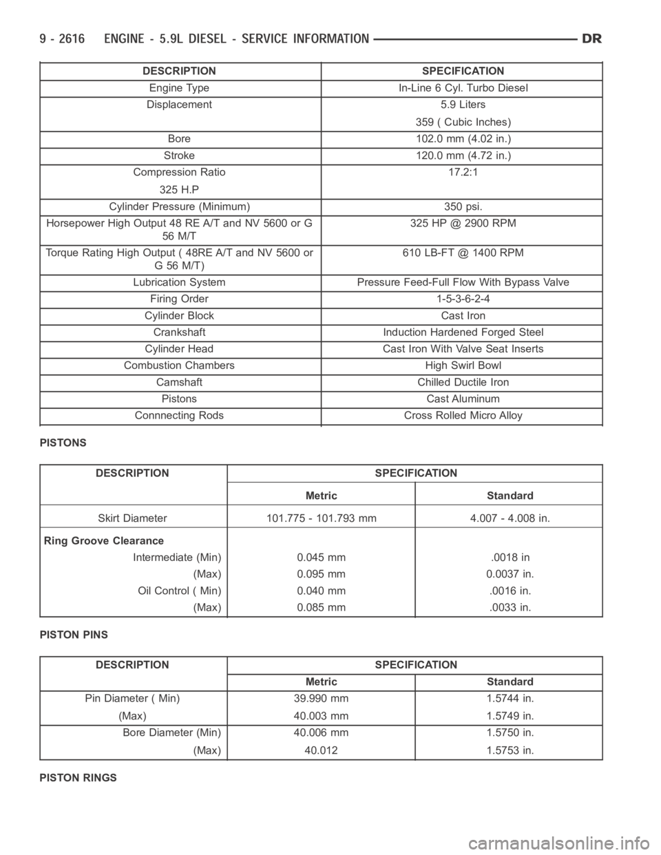
DESCRIPTION SPECIFICATION
Engine Type In-Line 6 Cyl. Turbo Diesel
Displacement 5.9 Liters
359 ( Cubic Inches)
Bore 102.0 mm (4.02 in.)
Stroke 120.0 mm (4.72 in.)
Compression Ratio 17.2:1
325 H.P
Cylinder Pressure (Minimum) 350 psi.
Horsepower High Output 48 RE A/T and NV 5600 or G
56 M/T325 HP @ 2900 RPM
Torque Rating High Output ( 48RE A/T and NV 5600 or
G56M/T)610 LB-FT @ 1400 RPM
Lubrication System Pressure Feed-Full Flow With Bypass Valve
Firing Order 1-5-3-6-2-4
Cylinder Block Cast Iron
Crankshaft Induction Hardened Forged Steel
Cylinder Head Cast Iron With Valve Seat Inserts
Combustion Chambers High Swirl Bowl
Camshaft Chilled Ductile Iron
Pistons Cast Aluminum
Connnecting Rods Cross Rolled Micro Alloy
PISTONS
DESCRIPTION SPECIFICATION
Metric Standard
Skirt Diameter 101.775 - 101.793 mm 4.007 - 4.008 in.
Ring Groove Clearance
Intermediate (Min) 0.045 mm .0018 in
(Max) 0.095 mm 0.0037 in.
Oil Control ( Min) 0.040 mm .0016 in.
(Max) 0.085 mm .0033 in.
PISTON PINS
DESCRIPTION SPECIFICATION
Metric Standard
Pin Diameter ( Min) 39.990 mm 1.5744 in.
(Max) 40.003 mm 1.5749 in.
Bore Diameter (Min) 40.006 mm 1.5750 in.
(Max) 40.012 1.5753 in.
PISTON RINGS
Page 1926 of 5267
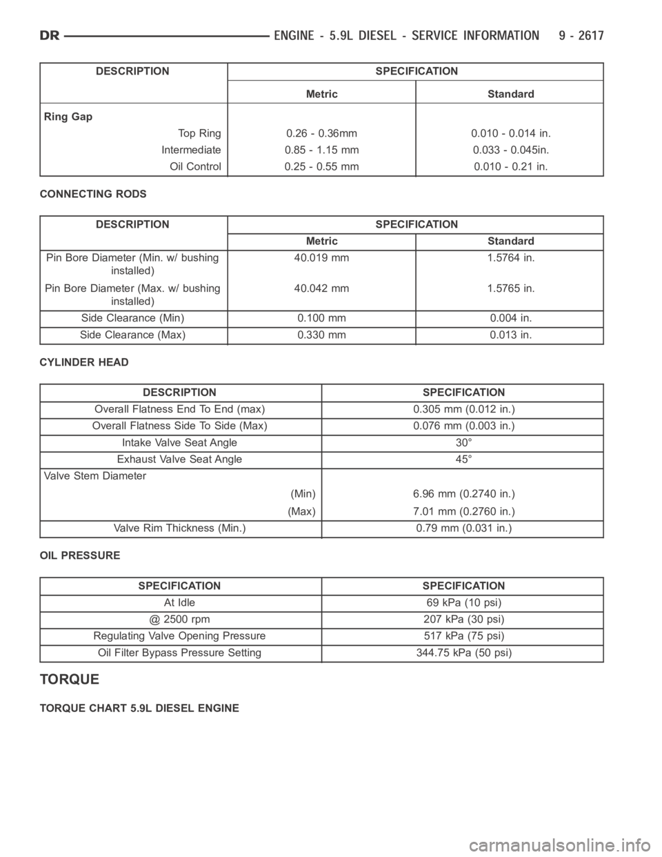
DESCRIPTION SPECIFICATION
Metric Standard
Ring Gap
Top Ring 0.26 - 0.36mm 0.010 - 0.014 in.
Intermediate 0.85 - 1.15 mm 0.033 - 0.045in.
Oil Control 0.25 - 0.55 mm 0.010 - 0.21 in.
CONNECTING RODS
DESCRIPTION SPECIFICATION
Metric Standard
Pin Bore Diameter (Min. w/ bushing
installed)40.019 mm 1.5764 in.
Pin Bore Diameter (Max. w/ bushing
installed)40.042 mm 1.5765 in.
Side Clearance (Min) 0.100 mm 0.004 in.
Side Clearance (Max) 0.330 mm 0.013 in.
CYLINDER HEAD
DESCRIPTION SPECIFICATION
Overall Flatness End To End (max) 0.305 mm (0.012 in.)
Overall Flatness Side To Side (Max) 0.076 mm (0.003 in.)
Intake Valve Seat Angle 30°
Exhaust Valve Seat Angle 45°
Va l v e S t e m D i a m e t e r
(Min) 6.96 mm (0.2740 in.)
(Max) 7.01 mm (0.2760 in.)
Valve Rim Thickness (Min.) 0.79 mm (0.031 in.)
OIL PRESSURE
SPECIFICATION SPECIFICATION
At Idle 69 kPa (10 psi)
@ 2500 rpm 207 kPa (30 psi)
Regulating Valve Opening Pressure 517 kPa (75 psi)
Oil Filter Bypass Pressure Setting 344.75 kPa (50 psi)
TORQUE
TORQUE CHART 5.9L DIESEL ENGINE
Page 1927 of 5267
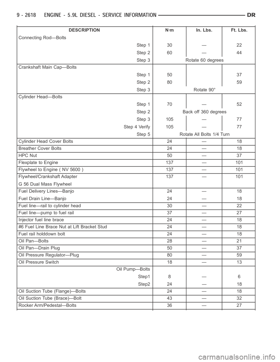
DESCRIPTION Nꞏm In. Lbs. Ft. Lbs.
Connecting Rod—Bolts
Step 1 30 — 22
Step 2 60 — 44
Step 3 Rotate 60 degrees
Crankshaft Main Cap—Bolts
Step 1 50 37
Step 2 80 59
Step 3 Rotate 90°
Cylinder Head—Bolts
Step 1 70 — 52
Step 2 Back off 360 degrees
Step 3 105 — 77
Step 4 Verify 105 — 77
Step 5 Rotate All Bolts 1/4 Turn
Cylinder Head Cover Bolts 24 — 18
Breather Cover Bolts 24 — 18
HPC Nut 50 — 37
Flexplate to Engine 137 — 101
Flywheel to Engine ( NV 5600 ) 137 — 101
Flywheel/Crankshaft Adapter 137 — 101
G 56 Dual Mass Flywheel
Fuel Delivery Lines—Banjo 24 — 18
Fuel Drain Line—Banjo 24 — 18
Fuel line—rail to cylinder head 30 — 22
Fuel line—pump to fuel rail 37 — 27
Injector fuel line brace 24 — 18
#6 Fuel Line Brace Nut at Lift Bracket Stud 24 — 18
Fuel rail holddown bolt 24 — 18
Oil Pan—Bolts 28 — 21
Oil Pan—Drain Plug 50 — 37
Oil Pressure Regulator—Plug 80 — 59
Oil Pressure Switch 18 — 13
Oil Pump—Bolts
Step1 8 — 6
Step2 24 — 18
Oil Suction Tube (Flange)—Bolts 24 — 18
Oil Suction Tube (Brace)—Bolt 43 — 32
Rocker Arm/Pedestal—Bolts 36 — 27
Page 1933 of 5267
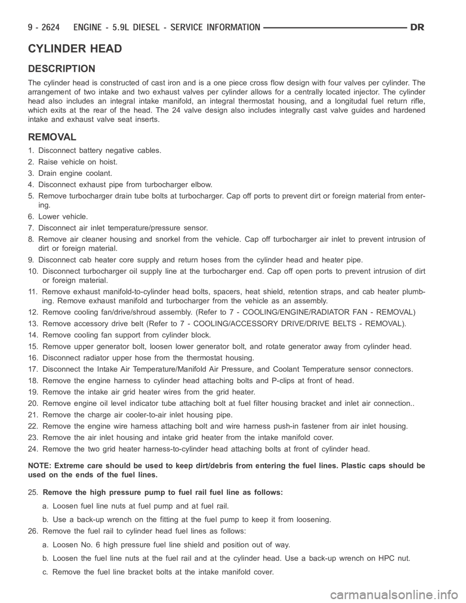
CYLINDER HEAD
DESCRIPTION
The cylinder head is constructed of cast iron and is a one piece cross flow design with four valves per cylinder. The
arrangement of two intake and two exhaust valves per cylinder allows for a centrally located injector. The cylinder
head also includes an integral intake manifold, an integral thermostat housing, and a longitudal fuel return rifle,
which exits at the rear of the head. The 24 valve design also includes integrally cast valve guides and hardened
intake and exhaust valve seat inserts.
REMOVAL
1. Disconnect battery negative cables.
2. Raise vehicle on hoist.
3. Drain engine coolant.
4. Disconnect exhaust pipe from turbocharger elbow.
5. Remove turbocharger drain tube bolts at turbocharger. Cap off ports to prevent dirt or foreign material from enter-
ing.
6. Lower vehicle.
7. Disconnect air inlet temperature/pressure sensor.
8. Remove air cleaner housing and snorkel from the vehicle. Cap off turbocharger air inlet to prevent intrusion of
dirt or foreign material.
9. Disconnect cab heater core supply and return hoses from the cylinder head and heater pipe.
10. Disconnect turbocharger oil supply line at the turbocharger end. Cap off open ports to prevent intrusion of dirt
or foreign material.
11. Remove exhaust manifold-to-cylinder head bolts, spacers, heat shield, retention straps, and cab heater plumb-
ing. Remove exhaust manifold and turbocharger from the vehicle as an assembly.
12. Remove cooling fan/drive/shroud assembly. (Refer to 7 - COOLING/ENGINE/RADIATOR FAN - REMOVAL)
13. Remove accessory drive belt (Refer to 7 - COOLING/ACCESSORY DRIVE/DRIVE BELTS - REMOVAL).
14. Remove cooling fan support from cylinder block.
15. Remove upper generator bolt, loosen lower generator bolt, and rotate generator away from cylinder head.
16. Disconnect radiator upper hose from the thermostat housing.
17. Disconnect the Intake Air Temperature/Manifold Air Pressure, and Coolant Temperature sensor connectors.
18. Remove the engine harness to cylinder head attaching bolts and P-clipsat front of head.
19. Remove the intake air grid heater wires from the grid heater.
20. Remove engine oil level indicator tube attaching bolt at fuel filter housing bracket and inlet air connection..
21. Remove the charge air cooler-to-air inlet housing pipe.
22. Remove the engine wire harness attaching bolt and wire harness push-infastener from air inlet housing.
23. Remove the air inlet housing and intake grid heater from the intake manifold cover.
24. Remove the two grid heater harness-to-cylinder head attaching bolts at front of cylinder head.
NOTE: Extreme care should be used to keep dirt/debris from entering the fuel lines. Plastic caps should be
used on the ends of the fuel lines.
25.Remove the high pressure pump to fuel rail fuel line as follows:
a. Loosen fuel line nuts at fuel pump and at fuel rail.
b. Use a back-up wrench on the fitting at the fuel pump to keep it from loosening.
26. Remove the fuel rail to cylinder head fuel lines as follows:
a. Loosen No. 6 high pressure fuel line shield and position out of way.
b. Loosen the fuel line nuts at the fuel rail and at the cylinder head. Use a back-up wrench on HPC nut.
c. Remove the fuel line bracket bolts at the intake manifold cover.
Page 1939 of 5267
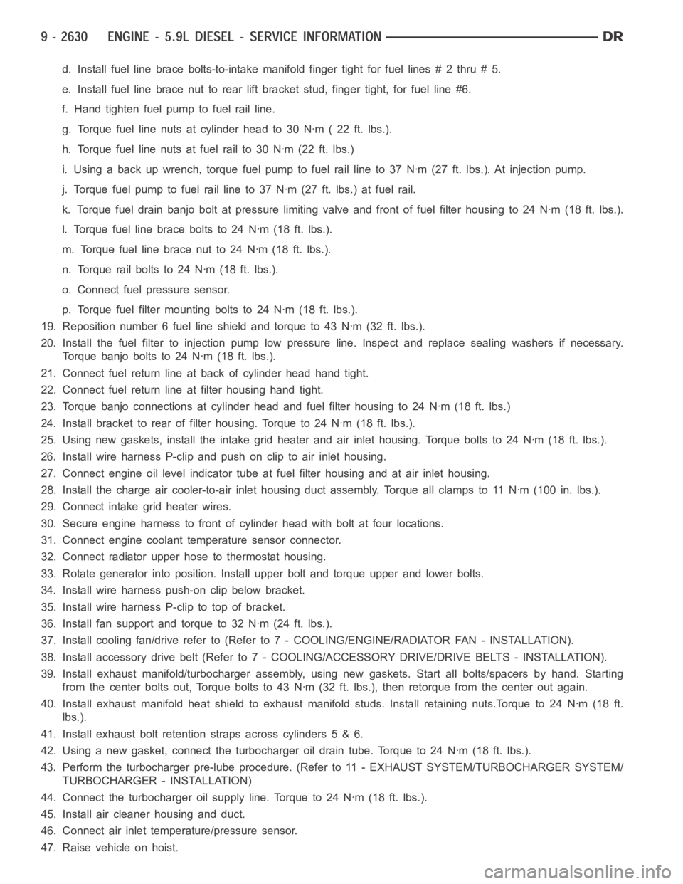
d. Install fuel line brace bolts-to-intake manifold finger tight for fuellines#2thru#5.
e. Install fuel line brace nut to rear lift bracket stud, finger tight, for fuel line #6.
f. Hand tighten fuel pump to fuel rail line.
g. Torque fuel line nuts at cylinder head to 30 Nꞏm ( 22 ft. lbs.).
h. Torque fuel line nuts at fuel rail to 30 Nꞏm (22 ft. lbs.)
i. Usingabackupwrench,torquefuelpumptofuelraillineto37Nꞏm(27ft.lbs.). At injection pump.
j. Torque fuel pump to fuel rail line to 37 Nꞏm (27 ft. lbs.) at fuel rail.
k. Torque fuel drain banjo bolt at pressure limiting valve and front of fuelfilter housing to 24 Nꞏm (18 ft. lbs.).
l. Torque fuel line brace bolts to 24 Nꞏm (18 ft. lbs.).
m. Torque fuel line brace nut to 24 Nꞏm (18 ft. lbs.).
n. Torque rail bolts to 24 Nꞏm (18 ft. lbs.).
o. Connect fuel pressure sensor.
p. Torque fuel filter mounting bolts to 24 Nꞏm (18 ft. lbs.).
19. Reposition number 6 fuel line shield and torque to 43 Nꞏm (32 ft. lbs.).
20. Install the fuel filter to injection pump low pressure line. Inspect and replace sealing washers if necessary.
Torque banjo bolts to 24 Nꞏm (18 ft. lbs.).
21. Connect fuel return line at back of cylinder head hand tight.
22. Connect fuel return line at filter housing hand tight.
23. Torque banjo connections at cylinder head and fuel filter housing to 24Nꞏm (18 ft. lbs.)
24. Install bracket to rear of filter housing. Torque to 24 Nꞏm (18 ft. lbs.).
25. Using new gaskets, install the intake grid heater and air inlet housing. Torque bolts to 24 Nꞏm (18 ft. lbs.).
26. Install wire harness P-clip and push on clip to air inlet housing.
27. Connect engine oil level indicator tube at fuel filter housing and at air inlet housing.
28. Install the charge air cooler-to-air inlet housing duct assembly. Torque all clamps to 11 Nꞏm (100 in. lbs.).
29. Connect intake grid heater wires.
30. Secure engine harness to front of cylinder head with bolt at four locations.
31. Connect engine coolant temperature sensor connector.
32. Connect radiator upper hose to thermostat housing.
33. Rotate generator into position. Install upper bolt and torque upper and lower bolts.
34. Install wire harness push-on clip below bracket.
35. Install wire harness P-clip to top of bracket.
36. Install fan support and torque to 32 Nꞏm (24 ft. lbs.).
37. Install cooling fan/drive refer to (Refer to 7 - COOLING/ENGINE/RADIATOR FAN - INSTALLATION).
38. Install accessory drive belt (Refer to 7 - COOLING/ACCESSORY DRIVE/DRIVE BELTS - INSTALLATION).
39. Install exhaust manifold/turbocharger assembly, using new gaskets.Start all bolts/spacers by hand. Starting
from the center bolts out, Torque bolts to 43 Nꞏm (32 ft. lbs.), then retorque from the center out again.
40. Install exhaust manifold heat shield to exhaust manifold studs. Install retaining nuts.Torque to 24 Nꞏm (18 ft.
lbs.).
41. Install exhaust bolt retention straps across cylinders 5 & 6.
42. Using a new gasket, connect the turbocharger oil drain tube. Torque to 24Nꞏm(18ft.lbs.).
43. Perform the turbocharger pre-lube procedure. (Refer to 11 - EXHAUST SYSTEM/TURBOCHARGER SYSTEM/
TURBOCHARGER - INSTALLATION)
44. Connect the turbocharger oil supply line. Torque to 24 Nꞏm (18 ft. lbs.).
45. Install air cleaner housing and duct.
46. Connect air inlet temperature/pressure sensor.
47. Raise vehicle on hoist.