2006 DODGE RAM SRT-10 oil pressure
[x] Cancel search: oil pressurePage 1856 of 5267
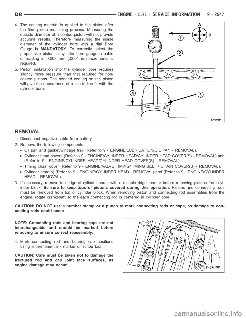
4. The coating material is applied to the piston after
the final piston machining process. Measuring the
outside diameter of a coated piston will not provide
accurate results. Therefore measuring the inside
diameter of the cylinder bore with a dial Bore
Gauge isMANDATORY. To correctly select the
proper size piston, a cylinder bore gauge capable
of reading in 0.003 mm (.0001 in.) increments is
required.
5. Piston installation intothe cylinder bore requires
slightly more pressure than that required for non-
coated pistons. The bonded coating on the piston
will give the appearance of a line-to-line fit with the
cylinder bore.
REMOVAL
1. Disconnect negative cable from battery.
2. Remove the following components:
Oil pan and gasket/windage tray (Refer to 9 - ENGINE/LUBRICATION/OIL PAN -REMOVAL).
Cylinder head covers (Refer to 9 - ENGINE/CYLINDER HEAD/CYLINDER HEAD COVER(S) - REMOVAL) and
(Refer to 9 - ENGINE/CYLINDER HEAD/CYLINDER HEAD COVER(S) - REMOVAL).
Timing chain cover (Refer to 9 - ENGINE/VALVE TIMING/TIMING BELT / CHAIN COVER(S) - REMOVAL).
Cylinder head(s) (Refer to 9 - ENGINE/CYLINDER HEAD - REMOVAL) and (Refer to 9 - ENGINE/CYLINDER
HEAD - REMOVAL).
3. If necessary, remove top ridge of cylinder bores with a reliable ridge reamer before removing pistons from cyl-
inder block.Be sure to keep tops of pistons covered during this operation.Pistons and connecting rods
must be removed from top of cylinder block. When removing piston and connecting rod assemblies from the
engine, rotate crankshaft so the each connecting rod is centered in cylinder bore.
CAUTION: DO NOT use a number stamp or a punch to mark connecting rods or caps,as damage to con-
necting rods could occur
NOTE: Connecting rods and bearing caps are not
interchangeable and should be marked before
removing to ensure correct reassembly.
4. Mark connecting rod and bearing cap positions
using a permanent ink marker or scribe tool.
CAUTION: Care must be taken not to damage the
fractured rod and cap joint face surfaces, as
engine damage may occur.
Page 1868 of 5267
SOLENOID-MDS
DESCRIPTION
The Multi Displacement System selectively deactivates cylinders 1,4,6,and 7, to improve fuel economy. It has two
modes of operation :
8 cylinders for acceleraton and heavy loads.
4 cylinders for cruising and city traffic.
The main components of the Multi Displacement System are :
Unique MDS camshaft.
Deactivating roller tappets.
4 control valves/solenoids.
control valve/solenoid wiring harness.
oil temp sensor.
OPERATION
Cylinder Deactivation
Trap an exhaust charge from a normal combustion event
Normal combustion event
Don’t open the exhaust valve
Don’t open the intake valve
Piston is an air spring
Cylinders deactivated in firing sequence
Cylinder Reactivation
Open the exhaust valve
Empty the cylinder
Open the intake valve
Normal combustion event
Cylinders reactivated in firing sequence
DIAGNOSIS AND TESTING
The Multi Displacement System has the following detectible issues:
Solenoid circuit
Fail to deactivate a cylinder(s)
Fail to reactivate a cylinder(s)
Low oil pressure
CONDITION POSSIBLE CAUSES CORRECTION
MDS does not activate 1. Low oil pressure 1. Check for proper oil pressure
2. Bad oil temp sensor 2. Replace oil temp sensor
3. Malfunctioning MDS Solenoid 3. Replace Solenoid
4. Malfunctioning MDS Tappet 4. Replace Tappet
MDS Does Not Deactivate 1. Low oil pressure 1. Check for proper oil pressure
2. Bad oil temp sensor 2. Replace oil temp sensor
3. Malfunctioning MDS Solenoid 3. Replace Solenoid
4. Malfunctioning MDS Tappet 4. Replace Tappet
Page 1875 of 5267
LUBRICATION
DIAGNOSIS AND TESTING
DIAGNOSIS AND TESTING - CHECKING ENGINE OIL PRESSURE
1. Remove oil pressure sending unit and install gauge assembly C-3292.
2. Run engine until thermostat opens.
3. Oil Pressure:
Curb Idle–25 kPa (4 psi) minimum
3000 rpm–170 - 758 kPa (25 - 110 psi)
4. If oil pressure is 0 at idle, shut off engine. Check for a clogged oil pick-up screen or a pressure relief valve stuck
open.
DIAGNOSIS AND TESTING - ENGINE OIL LEAK
Begin with a thorough visual inspection of the engine, particularly at thearea of the suspected leak. If an oil leak
source is not readily identifiable, thefollowingstepsshouldbefollowed:
1. Do not clean or degrease the engine at this time because some solvents maycause rubber to swell, temporarily
stopping the leak.
2. Add an oil soluble dye (use as recommended by manufacturer). Start the engine and let idle for approximately 15
minutes. Check the oil dipstick to make sure the dye is thoroughly mixed as indicated with a bright yellow color
under a black light.
3. Using a black light, inspect the entire engine for fluorescent dye, particularly at the suspected area of oil leak. If
the oil leak is found and identified, repair per service manual instructions.
4. If dye is not observed, drive the vehicle at various speeds for approximately 24 km (15 miles), and repeat inspec-
tion.If the oil leak source is not positively identified at this time, proceed with the air leak detection test
method.
Air Leak Detection Test Method
1. Remove the PCV valve from the IAFM. Cap or plug the PCV valve grommet.
2. Attach an air hose with pressure gauge and regulator to the dipstick tube.
CAUTION: Do not subject the engine assembly to more than 20.6 kPa (3 PSI) of test pressure.
3. Gradually apply air pressure from 1 psi to 2.5 psi maximum while applyingsoapy water at the suspected source.
Adjust the regulator to the suitable test pressure that provide the best bubbles which will pinpoint the leak
source. If the oil leak is detected and identified, repair per service manual procedures.
4. If the leakage occurs at the rear oil seal area, refer to the section, Inspection for Rear Seal Area Leak.
5. If no leaks are detected, turn off the air supply and remove the air hose and all plugs and caps. Install the PCV
valve.
6. Clean the oil off the suspect oil leak area using a suitable solvent. Drive the vehicle at various speeds approx-
imately 24 km (15 miles). Inspect the engine for signs of an oil leak by usinga black light.
INSPECTION FOR REAR SEAL AREA LEAKS
Since it is sometimes difficult to determine the source of an oil leak in therear seal area of the engine, a more
involved inspection is necessary. The following steps should be followedto help pinpoint the source of the leak.
If the leakage occurs at the crankshaft rear oil seal area:
1. Disconnect the battery.
2. Raise the vehicle.
3. Remove torque converter or clutch housing cover and inspect rear of block for evidence of oil. Use a black light
to check for the oil leak:
a. Circular spray pattern generally indicates seal leakage or crankshaftdamage.
Page 1877 of 5267
OIL
STANDARD PROCEDURE - ENGINE OIL SERVICE
The engine oil level indicator is located at the left hand of the engine on the 5.7L engines.
CRANKCASE OIL LEVEL INSPECTION
CAUTION: Do not overfill crankcase with engine oil, pressure loss or oil foaming can result.
Inspect engine oil level approximately every 800 kilometers (500 miles).Unless the engine has exhibited loss of oil
pressure, run the engine for about ten minutes before checking oil level. Checking engine oil level on a cold engine
is not accurate.
To ensure proper lubrication of an engine, the engine oil must be maintained at an acceptable level. The acceptable
levels are indicated between the ADD and SAFE marks on the engine oil dipstick.
1. Position vehicle on level surface.
2. With engine OFF, allow approximately five minutes for oil to settle to bottom of crankcase, remove engine oil
dipstick.
3. Wipe dipstick clean.
4. Install dipstick and verify it is seated in the tube.
5. Remove dipstick, with handle held above the tip, take oil level reading.
6. Add oil only if level is below the ADD mark on dipstick.
ENGINE OIL CHANGE
Change engine oil at mileage and time intervals described in Maintenance Schedules (Refer to LUBRICATION &
MAINTENANCE/MAINTENANCESCHEDULES - DESCRIPTION).
Run engine until achieving normal operating temperature.
1. Position the vehicle on a level surface and turn engine off.
2. Hoist and support vehicle on safety stands.
3. Remove oil fill cap.
4. Place a suitable drain pan under crankcase drain.
5. Remove drain plug from crankcase and allow oil to drain into pan. Inspectdrain plug threads for stretching or
other damage. Replace drain plug if damaged.
6. Install drain plug in crankcase. Torque to 34 Nꞏm ( 25 ft. lbs.).
7. Lower vehicle and fill crankcase with specified type and amount of engine oil described in this section.
8. Install oil fill cap.
9. Start engine and inspect for leaks.
10. Stop engine and inspect oil level.
USED ENGINE OIL DISPOSAL
Care should be exercised when disposing used engine oil after it has been drained from a vehicle engine. Refer to
the WARNING at beginning of this section.
Page 1883 of 5267
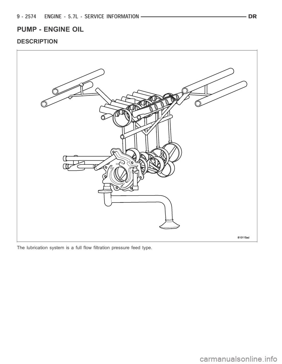
PUMP - ENGINE OIL
DESCRIPTION
The lubrication system is a full flow filtration pressure feed type.
Page 1885 of 5267
INSPECTION
CAUTION: Oil pump pressure relief valve and
spring should not be removed from the oil pump.
If these components are disassembled and or
removed from the pump the entire oil pump
assembly must be replaced.
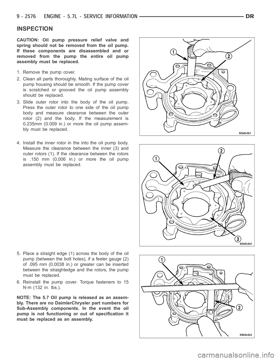
1. Remove the pump cover.
2. Clean all parts thoroughly. Mating surface of the oil
pump housing should be smooth. If the pump cover
is scratched or grooved the oil pump assembly
should be replaced.
3. Slide outer rotor into the body of the oil pump.
Press the outer rotor to one side of the oil pump
body and measure clearance between the outer
rotor (2) and the body. If the measurement is
0.235mm (0.009 in.) or more the oil pump assem-
bly must be replaced.
4. Install the inner rotor in the into the oil pump body.
Measure the clearance between the inner (3) and
outer rotors (1). If the clearance between the rotors
is .150 mm (0.006 in.) or more the oil pump
assembly must be replaced.
5. Place a straight edge (1) across the body of the oil
pump (between the bolt holes), if a feeler gauge (2)
of .095 mm (0.0038 in.) or greater can be inserted
between the straightedge and the rotors, the pump
must be replaced.
6. Reinstall the pump cover. Torque fasteners to 15
Nꞏm (132 in. lbs.).
NOTE: The 5.7 Oil pump is released as an assem-
bly. There are no DaimlerChrysler part numbers for
Sub-Assembly components. In the event the oil
pump is not functioning or out of specification it
must be replaced as an assembly.
Page 1904 of 5267
SEAL - CRANKSHAFT OIL - FRONT
REMOVAL ................................. 2667
INSTALLATION ............................. 2668
SEAL - CRANKSHAFT OIL - REAR
REMOVAL ................................. 2670
INSTALLATION ............................. 2670
RETAINER - CRANK REAR OIL SEAL
REMOVAL ................................. 2671
INSTALLATION ............................. 2671
TAPPETS - VALVE
REMOVAL ................................. 2673
CLEANING ................................. 2674
INSPECTION ............................... 2674
INSTALLATION ............................. 2674
PISTON & CONNECTING ROD
DESCRIPTION ............................. 2677
STANDARD PROCEDURE - HEAD GASKET
SELECTION .............................. 2677
REMOVAL ................................. 2678
CLEANING—PISTON AND CONNECTING ROD . 2678
INSPECTION
INSPECTION - PISTONS .................. 2678
INSPECTION - CONNECTING ROD........ 2680
INSTALLATION ............................. 2680
RINGS - PISTON
STANDARD PROCEDURE - PISTON RING
FITTING .................................. 2682
DAMPER - CRANKSHAFT
REMOVAL ................................. 2684
INSPECTION ............................... 2684
INSTALLATION ............................. 2684
MOUNT - FRONT
REMOVAL ................................. 2685
INSTALLATION ............................. 2686
MOUNT - REAR
REMOVAL ................................. 2687
INSTALLATION ............................. 2687
LUBRICATION
DESCRIPTION ............................. 2688
OPERATION ............................... 2688
DIAGNOSIS AND TESTING—ENGINE OIL
PRESSURE .............................. 2692
OIL
STANDARD PROCEDURE
STANDARD PROCEDURE - ENGINE OIL
LEVEL................................... 2693STANDARD PROCEDURE - ENGINE OIL
SERVICE................................. 2693
COOLER - ENGINE OIL & LINES
CLEANING
CLEANING AND INSPECTION............. 2694
FILTER - ENGINE OIL
REMOVAL ................................. 2695
INSTALLATION ............................. 2695
PA N - E N G I N E O I L
REMOVAL ................................. 2696
CLEANING ................................. 2696
INSPECTION............................... 2696
INSTALLATION ............................. 2696
VALVE-OILPRESSURERELIEF
REMOVAL ................................. 2697
CLEANING ................................. 2697
INSPECTION............................... 2697
INSTALLATION ............................. 2697
SWITCH - OIL PRESSURE
REMOVAL ................................. 2698
INSTALLATION ............................. 2698
PUMP - ENGINE OIL
REMOVAL ................................. 2699
CLEANING ................................. 2699
INSPECTION............................... 2699
INSTALLATION ............................. 2700
MANIFOLD - INTAKE
REMOVAL ................................. 2702
CLEANING ................................. 2703
INSPECTION............................... 2703
INSTALLATION ............................. 2703
MANIFOLD - EXHAUST
REMOVAL ................................. 2704
CLEANING ................................. 2704
INSPECTION............................... 2704
INSTALLATION ............................. 2704
VALVE TIMING
STANDARD PROCEDURE - TIMING
VERIFICATION ........................... 2706
CASE - FRONT
REMOVAL ................................. 2707
INSTALLATION ............................. 2708
COVER - TIMING
REMOVAL ................................. 2710
INSTALLATION ............................. 2710
Page 1906 of 5267
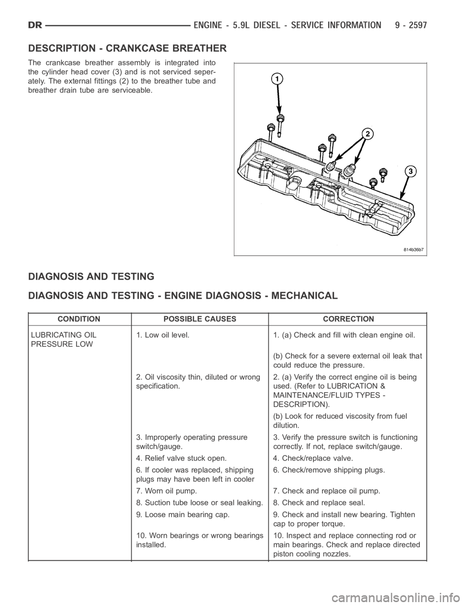
DESCRIPTION - CRANKCASE BREATHER
The crankcase breather assembly is integrated into
the cylinder head cover (3) and is not serviced seper-
ately. The external fittings (2) to the breather tube and
breather drain tube are serviceable.
DIAGNOSIS AND TESTING
DIAGNOSIS AND TESTING - ENGINE DIAGNOSIS - MECHANICAL
CONDITION POSSIBLE CAUSES CORRECTION
LUBRICATING OIL
PRESSURE LOW1. Low oil level. 1. (a) Check and fill with clean engine oil.
(b) Check for a severe external oil leak that
could reduce the pressure.
2. Oil viscosity thin, diluted or wrong
specification.2. (a) Verify the correct engine oil is being
used. (Refer to LUBRICATION &
MAINTENANCE/FLUID TYPES -
DESCRIPTION).
(b) Look for reduced viscosity from fuel
dilution.
3. Improperly operating pressure
switch/gauge.3. Verify the pressure switch is functioning
correctly. If not, replace switch/gauge.
4. Relief valve stuck open. 4. Check/replace valve.
6. If cooler was replaced, shipping
plugs may have been left in cooler6. Check/remove shipping plugs.
7. Worn oil pump. 7. Check and replace oil pump.
8. Suction tube loose or seal leaking. 8. Check and replace seal.
9. Loose main bearing cap. 9. Check and install new bearing. Tighten
cap to proper torque.
10. Worn bearings or wrong bearings
installed.10. Inspect and replace connecting rod or
main bearings. Check and replace directed
piston cooling nozzles.