2006 DODGE RAM SRT-10 oil pressure
[x] Cancel search: oil pressurePage 1720 of 5267
LUBRICATION
DESCRIPTION
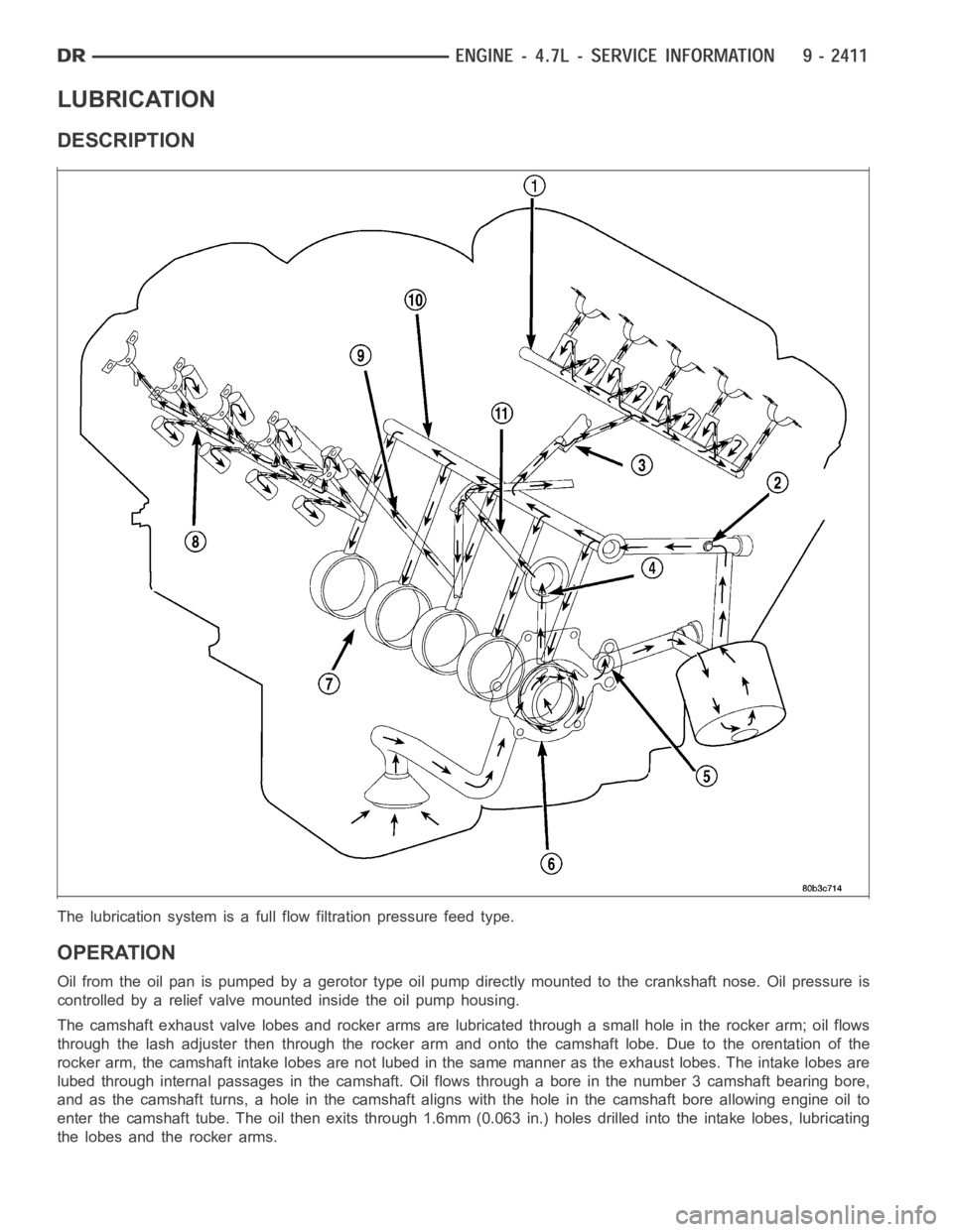
The lubrication system is a full flow filtration pressure feed type.
OPERATION
Oil from the oil pan is pumped by a gerotor type oil pump directly mounted to the crankshaft nose. Oil pressure is
controlled by a relief valve mounted inside the oil pump housing.
The camshaft exhaust valve lobes and rocker arms are lubricated through a small hole in the rocker arm; oil flows
through the lash adjuster then through the rocker arm and onto the camshaftlobe. Due to the orentation of the
rocker arm, the camshaft intake lobes are not lubed in the same manner as theexhaust lobes. The intake lobes are
lubed through internal passages in the camshaft. Oil flows through a bore in the number 3 camshaft bearing bore,
and as the camshaft turns, a hole in the camshaft aligns with the hole in the camshaft bore allowing engine oil to
enter the camshaft tube. The oil then exits through 1.6mm (0.063 in.) holesdrilled into the intake lobes, lubricating
the lobes and the rocker arms.
Page 1721 of 5267
Engine Lubrication Flow Chart—Block: Table 1
FROM TO
Oil Pickup Tube Oil Pump
Oil Pump Oil Filter
Oil Filter Block Main Oil Gallery
Block Main Oil Gallery 1. Crankshaft Main Journal
2. Left Cylinder Head*
3. Right Cylinder Head*
Crankshaft Main Journals Crankshaft Rod Journals
Crankshaft Number One Main Journal 1.Front Timing Chain Idler Shaft
2.Both Secondary Chain Tensioners
Left Cylinder Head See Table 2
Right Cylinder Head See Table 2
* The cylinder head gaskets have an oil restricter to control oil flow to thecylinder heads.
Engine Lubrication Flow Chart—Cylinder Heads: Table 2
FROM TO
Cylinder Head Oil Port (in bolt hole) Diagonal Cross Drilling to Main Oil Gallery
Main Oil Gallery (drilled through headfrom rear to front) 1. Base of Camshaft Towers
2. Lash Adjuster Towers
Base of Camshaft Towers Vertical Drilling Through Tower to Camshaft Bearings**
Lash Adjuster Towers Diagonal Drillings to Hydraulic Lash Adjuster Pockets
** The number three camshaft bearing journal feeds oil into the hollow camshaft tubes. Oil is routed to the intake
lobes, which have oil passages drilled into them to lubricate the rocker arms.
DIAGNOSIS AND TESTING
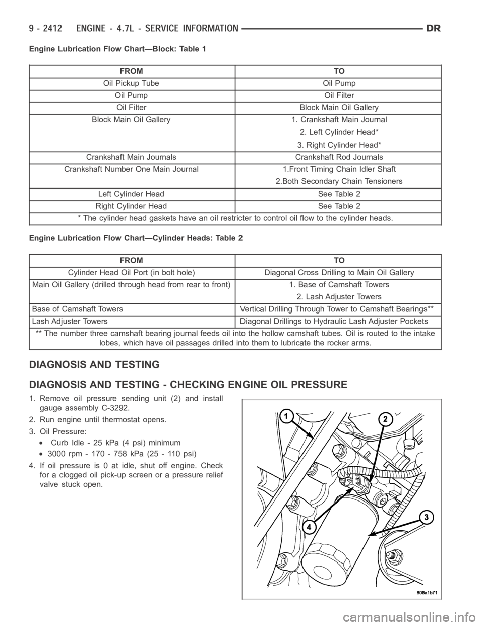
DIAGNOSIS AND TESTING - CHECKING ENGINE OIL PRESSURE
1. Remove oil pressure sending unit (2) and install
gauge assembly C-3292.
2. Run engine until thermostat opens.
3. Oil Pressure:
Curb Idle - 25 kPa (4 psi) minimum
3000 rpm - 170 - 758 kPa (25 - 110 psi)
4. If oil pressure is 0 at idle, shut off engine. Check
for a clogged oil pick-up screen or a pressure relief
valve stuck open.
Page 1722 of 5267
DIAGNOSIS AND TESTING - ENGINE OIL LEAK
Begin with a thorough visual inspection of the engine, particularly at thearea of the suspected leak. If an oil leak
source is not readily identifiable, thefollowingstepsshouldbefollowed:
1. Do not clean or degrease the engine at this time because some solvents maycause rubber to swell, temporarily
stopping the leak.
2. Add an oil soluble dye (use as recommended by manufacturer). Start the engine and let idle for approximately 15
minutes. Check the oil dipstick to make sure the dye is thoroughly mixed as indicated with a bright yellow color
under a black light.
3. Using a black light, inspect the entire engine for fluorescent dye, particularly at the suspected area of oil leak. If
the oil leak is found and identified, repair per service manual instructions.
4. If dye is not observed, drive the vehicle at various speeds for approximately 24 km (15 miles), and repeat inspec-
tion.If the oil leak source is not positively identified at this time, proceed with the air leak detection test method.
Air Leak Detection Test Method
1. Disconnect the breather cap to air cleaner hose at the breather cap end. Cap or plug breather cap nipple.
2. Remove the PCV valve from the cylinder head cover. Cap or plug the PCV valvegrommet.
3. Attach an air hose with pressure gauge and regulator to the dipstick tube.
CAUTION: Do not subject the engine assembly to more than 20.6 kPa (3 PSI) of test pressure.
4. Gradually apply air pressure from 1 psi to 2.5 psi maximum while applyingsoapy water at the suspected source.
Adjust the regulator to the suitable test pressure that provide the best bubbles which will pinpoint the leak
source. If the oil leak is detected and identified, repair per service manual procedures.
5. If the leakage occurs at the rear oil seal area, refer to the section, Inspection for Rear Seal Area Leak.
6. If no leaks are detected, turn off the air supply and remove the air hose and all plugs and caps. Install the PCV
valve and breather cap hose.
7. Clean the oil off the suspect oil leak area using a suitable solvent. Drive the vehicle at various speeds approx-
imately 24 km (15 miles). Inspect the engine for signs of an oil leak by usinga black light.
INSPECTION FOR REAR SEAL AREA LEAKS
Since it is sometimes difficult to determine the source of an oil leak in therear seal area of the engine, a more
involved inspection is necessary. The following steps should be followedto help pinpoint the source of the leak.
If the leakage occurs at the crankshaft rear oil seal area:
1. Disconnect the battery.
2. Raise the vehicle.
3. Remove torque converter or clutch housing cover and inspect rear of block for evidence of oil. Use a black light
to check for the oil leak:
a. Circular spray pattern generally indicates seal leakage or crankshaftdamage.
b. Where leakage tends to run straight down, possible causes are a porous block, oil galley pipe plugs, oil filter
runoff, and main bearing cap to cylinder block mating surfaces.
4. If no leaks are detected, pressurize the crankcase as outlined in the, Inspection (Engine oil Leaks in general)
CAUTION: Do not exceed 20.6 kPa (3 psi).
5. If the leak is not detected, very slowly turn the crankshaft and watch forleakage. If a leak is detected between
the crankshaft and seal while slowly turning the crankshaft, it is possible the crankshaft seal surface is damaged.
The seal area on the crankshaft could have minor nicks or scratches that canbe polished out with emery cloth.
CAUTION: Use extreme caution when crankshaft polishing is necessary to remove minor nicks and
scratches. The crankshaft seal flange is especially machined to complement the function of the rear oil seal.
6. For bubbles that remain steady with shaft rotation, no further inspection can be done until disassembled.
Page 1723 of 5267
OIL
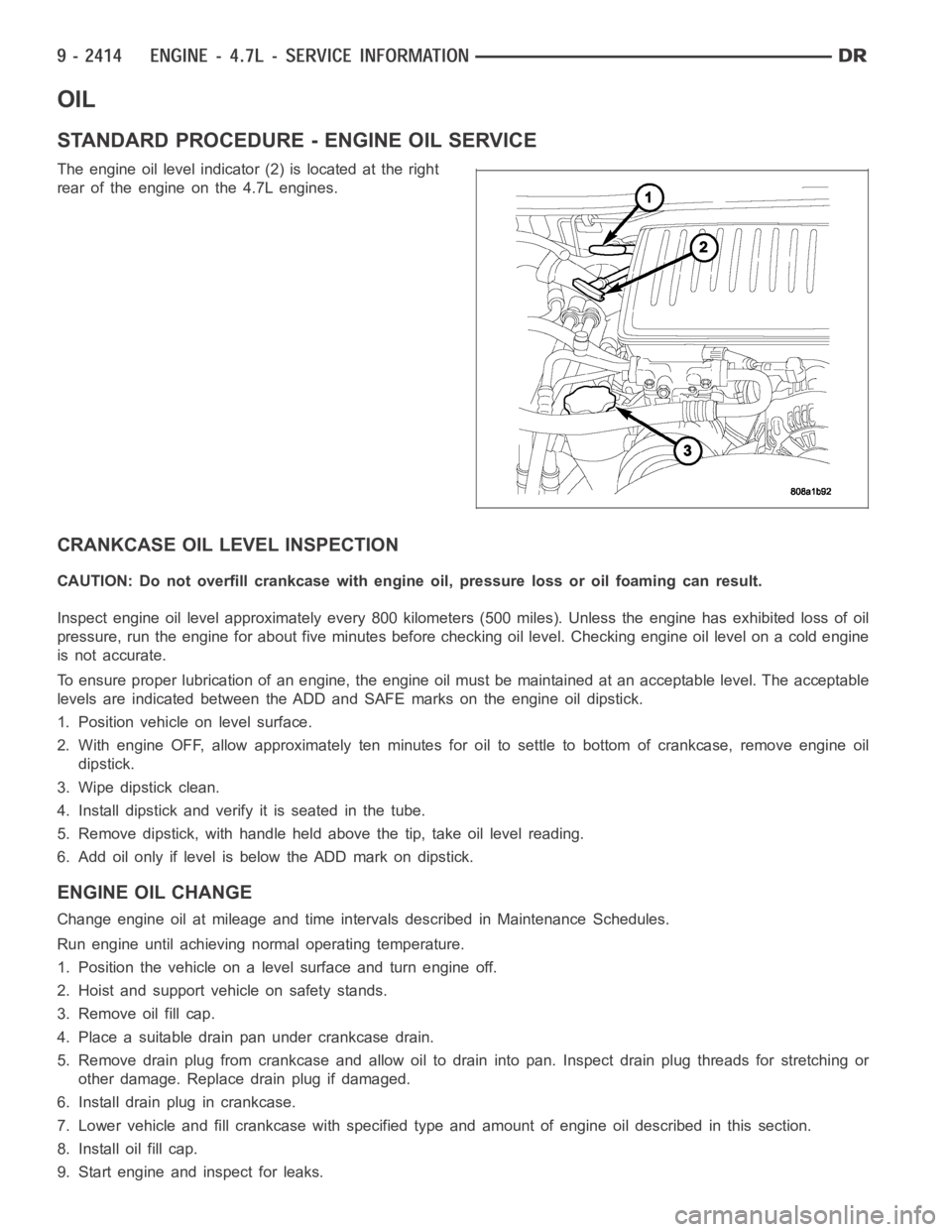
STANDARD PROCEDURE - ENGINE OIL SERVICE
The engine oil level indicator (2) is located at the right
rear of the engine on the 4.7L engines.
CRANKCASE OIL LEVEL INSPECTION
CAUTION: Do not overfill crankcase with engine oil, pressure loss or oil foaming can result.
Inspect engine oil level approximately every 800 kilometers (500 miles).Unless the engine has exhibited loss of oil
pressure, run the engine for about five minutes before checking oil level.Checking engine oil level on a cold engine
is not accurate.
To ensure proper lubrication of an engine, the engine oil must be maintained at an acceptable level. The acceptable
levels are indicated between the ADD and SAFE marks on the engine oil dipstick.
1. Position vehicle on level surface.
2. With engine OFF, allow approximately ten minutes for oil to settle to bottom of crankcase, remove engine oil
dipstick.
3. Wipe dipstick clean.
4. Install dipstick and verify it is seated in the tube.
5. Remove dipstick, with handle held above the tip, take oil level reading.
6. Add oil only if level is below the ADD mark on dipstick.
ENGINE OIL CHANGE
Change engine oil at mileage and time intervals described in Maintenance Schedules.
Run engine until achieving normal operating temperature.
1. Position the vehicle on a level surface and turn engine off.
2. Hoist and support vehicle on safety stands.
3. Remove oil fill cap.
4. Place a suitable drain pan under crankcase drain.
5. Remove drain plug from crankcase and allow oil to drain into pan. Inspectdrain plug threads for stretching or
other damage. Replace drain plug if damaged.
6. Install drain plug in crankcase.
7. Lower vehicle and fill crankcase with specified type and amount of engine oil described in this section.
8. Install oil fill cap.
9. Start engine and inspect for leaks.
Page 1727 of 5267
SWITCH - OIL PRESSURE
DESCRIPTION
DESCRIPTION
The 3 wire, solid-state engine oil pressure sensor (sending unit) is located in an engine oil pressure gallery.
DESCRIPTION
The 3–wire, electrical/mechanical engine oil pressure sensor (sending unit) is located in an engine oil pressure gal-
lery.
OPERATION
OPERATION
The oil pressure sensor uses three circuits. They are:
A 5 volt power supply from the Powertrain Control Module (PCM)
A sensor ground through the PCM’s sensor return
A signal to the PCM relating to engine oil pressure
The oil pressure sensor has a 3 wire electrical function very much like the Manifold Absolute Pressure (MAP) sen-
sor. Meaning different pressures relate to different output voltages.
A 5 volt supply is sent to the sensor from the PCM to power up the sensor. The sensor returns a voltage signal
back to the PCM relating to engine oil pressure. This signal is then transferred (bussed) to the instrument panel on
either a CCD or PCI bus circuit (depending on vehicle line) to operate the oil pressure gauge and the check gauges
lamp. Ground for the sensor is provided by the PCM through a low-noise sensor return.
OPERATION
The oil pressure sensor uses two circuits. They are:
A signal to the PCM relating to engine oil pressure
A sensor ground through the PCM’s sensor return
The oil pressure sensor returns a voltage signal back to the PCM relating toengine oil pressure. This signal is then
transferred (bussed) to the instrument panel on a CCD bus circuit to operate the oil pressure gauge and the check
gauges lamp. Ground for the sensor is provided by the PCM through a low-noise sensor return.
Page 1728 of 5267
REMOVAL
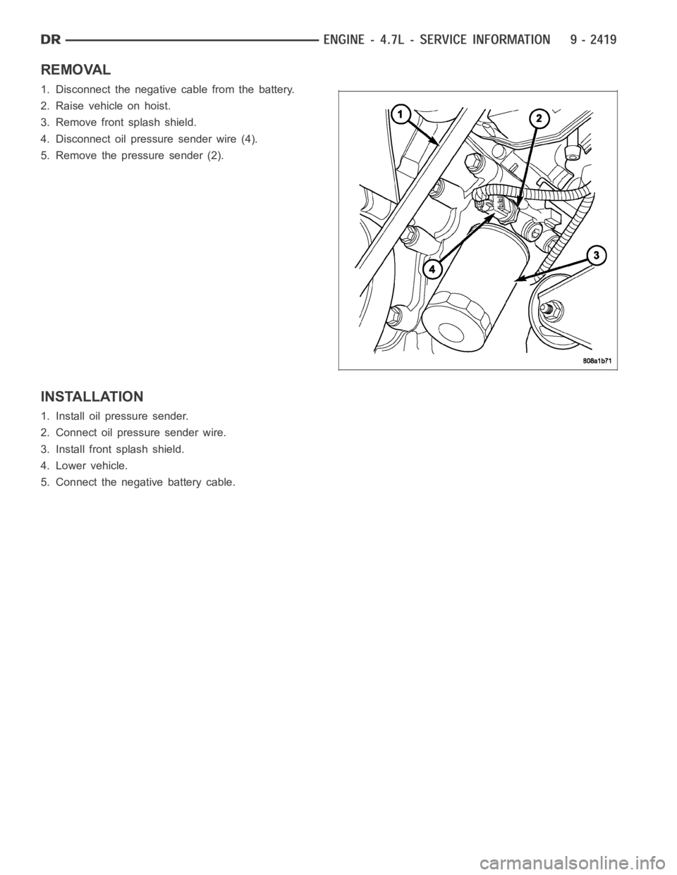
1. Disconnect the negative cable from the battery.
2. Raise vehicle on hoist.
3. Remove front splash shield.
4. Disconnect oil pressure sender wire (4).
5. Remove the pressure sender (2).
INSTALLATION
1. Install oil pressure sender.
2. Connect oil pressure sender wire.
3. Install front splash shield.
4. Lower vehicle.
5. Connect the negative battery cable.
Page 1729 of 5267
PUMP - ENGINE OIL
REMOVAL
1. Remove the oil pan and pick-up tube (Refer to 9 - ENGINE/LUBRICATION/OILPA N - R E M O VA L ) .
2. Remove the timing chain cover (Refer to 9 - ENGINE/VALVE TIMING/TIMING BELT / CHAIN COVER(S) -
REMOVAL).
3. Remove the timing chains and tensioners (Refer to 9 - ENGINE/VALVE TIMING/TIMING BELT/CHAIN AND
SPROCKETS - REMOVAL).
4. Remove the four bolts, primary timing chain tensioner and the oil pump.
DISASSEMBLY
1. Remove oil pump cover screws and lift off cover plate.
2. Remove pump inner and outer rotors.
NOTE: Once the oil pressure relief valve, cup plug, and pin are removed, thepump assembly must be
replaced.
3. If it is necessary to remove the pressure relief valve, drive the roll pinfrom pump housing and remove cup plug,
spring and valve.
CLEANING
1. Wash all parts in a suitable solvent.
INSPECTION
CAUTION: Oil pump pressure relief valve and
spring should not be removed from the oil pump.
If these components are disassembled and or
removed from the pump the entire oil pump
assembly must be replaced.
1. Clean all parts thoroughly. Mating surface of the oil
pump housing should be smooth. If the pump cover
is scratched or grooved the oil pump assembly
should be replaced.
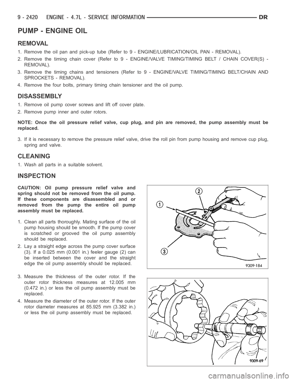
2. Lay a straight edge across the pump cover surface
(3). If a 0.025 mm (0.001 in.) feeler gauge (2) can
be inserted between the cover and the straight
edge the oil pump assembly should be replaced.
3. Measure the thickness of the outer rotor. If the
outer rotor thickness measures at 12.005 mm
(0.472 in.) or less the oil pump assembly must be
replaced.
4. Measure the diameter of the outer rotor. If the outer
rotor diameter measures at 85.925 mm (3.382 in.)
or less the oil pump assembly must be replaced.
Page 1731 of 5267
8. Place a straight edge (1) across the body of the oil
pump (between the bolt holes), if a feeler gauge (2)
of .095 mm (0.0038 in.) or greater can be inserted
between the straightedge and the rotors, the pump
must be replaced.
NOTE: The 3.7L/4.7L Oil pump is released as an
assembly. There are no DaimlerChrysler part num-
bers for Sub-Assembly components. In the event
the oil pump is not functioning or out of specifica-
tion it must be replaced as an assembly.
ASSEMBLY
1. Wash all parts in a suitable solvent and inspect carefully for damage or wear.
2. Install inner and outer rotors
3. Install oil pump cover plate and install cover bolts and tighten them to 12Nꞏm(105in.lbs.).
4. Prime oil pump before installation by filling rotor cavity with engine oil.
5. If oil pressure is low and pump is within specifications, inspect for worn engine bearings or other causes for oil
pressure loss.
INSTALLATION
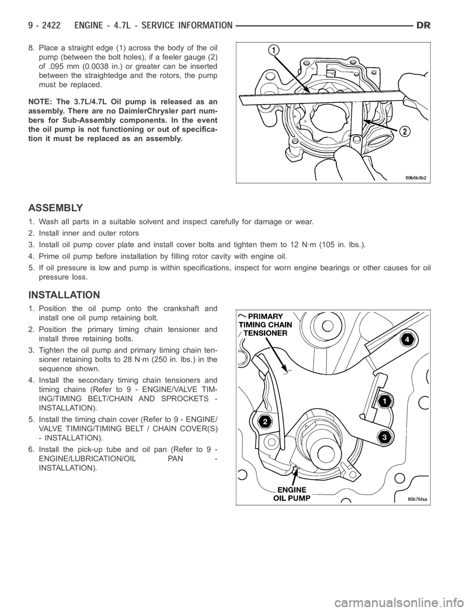
1. Position the oil pump onto the crankshaft and
install one oil pump retaining bolt.
2. Position the primary timing chain tensioner and
install three retaining bolts.
3. Tighten the oil pump and primary timing chain ten-
sioner retaining bolts to 28 Nꞏm (250 in. lbs.) in the
sequence shown.
4. Install the secondary timing chain tensioners and
timing chains (Refer to 9 - ENGINE/VALVE TIM-
ING/TIMING BELT/CHAIN AND SPROCKETS -
INSTALLATION).
5. Install the timing chain cover (Refer to 9 - ENGINE/
VALVE TIMING/TIMING BELT / CHAIN COVER(S)
- INSTALLATION).
6. Install the pick-up tube and oil pan (Refer to 9 -
ENGINE/LUBRICATION/OIL PAN -
INSTALLATION).