2006 DODGE RAM SRT-10 oil pressure
[x] Cancel search: oil pressurePage 1504 of 5267
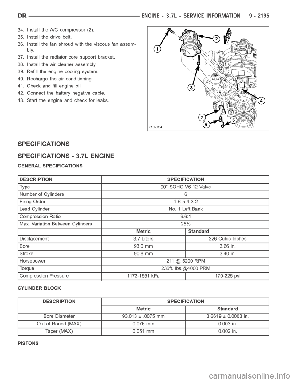
34. Install the A/C compressor (2).
35. Install the drive belt.
36. Install the fan shroud with the viscous fan assem-
bly.
37. Install the radiator core support bracket.
38. Install the air cleaner assembly.
39. Refill the engine cooling system.
40. Recharge the air conditioning.
41. Check and fill engine oil.
42. Connect the battery negative cable.
43. Start the engine and check for leaks.
SPECIFICATIONS
SPECIFICATIONS - 3.7L ENGINE
GENERAL SPECIFICATIONS
DESCRIPTION SPECIFICATION
Type 90°SOHCV612Valve
Number of Cylinders 6
Firing Order 1-6-5-4-3-2
Lead Cylinder No. 1 Left Bank
Compression Ratio 9.6:1
Max. Variation Between Cylinders 25%
Metric Standard
Displacement 3.7 Liters 226 Cubic Inches
Bore 93.0 mm 3.66 in.
Stroke 90.8 mm 3.40 in.
Horsepower 211 @ 5200 RPM
Torque 236ft. lbs.@4000 PRM
Compression Pressure 1172-1551 kPa 170-225 psi
CYLINDER BLOCK
DESCRIPTION SPECIFICATION
Metric Standard
Bore Diameter 93.013 ± .0075 mm 3.6619 ± 0.0003 in.
Out of Round (MAX) 0.076 mm 0.003 in.
Taper (MAX) 0.051 mm 0.002 in.
PISTONS
Page 1508 of 5267
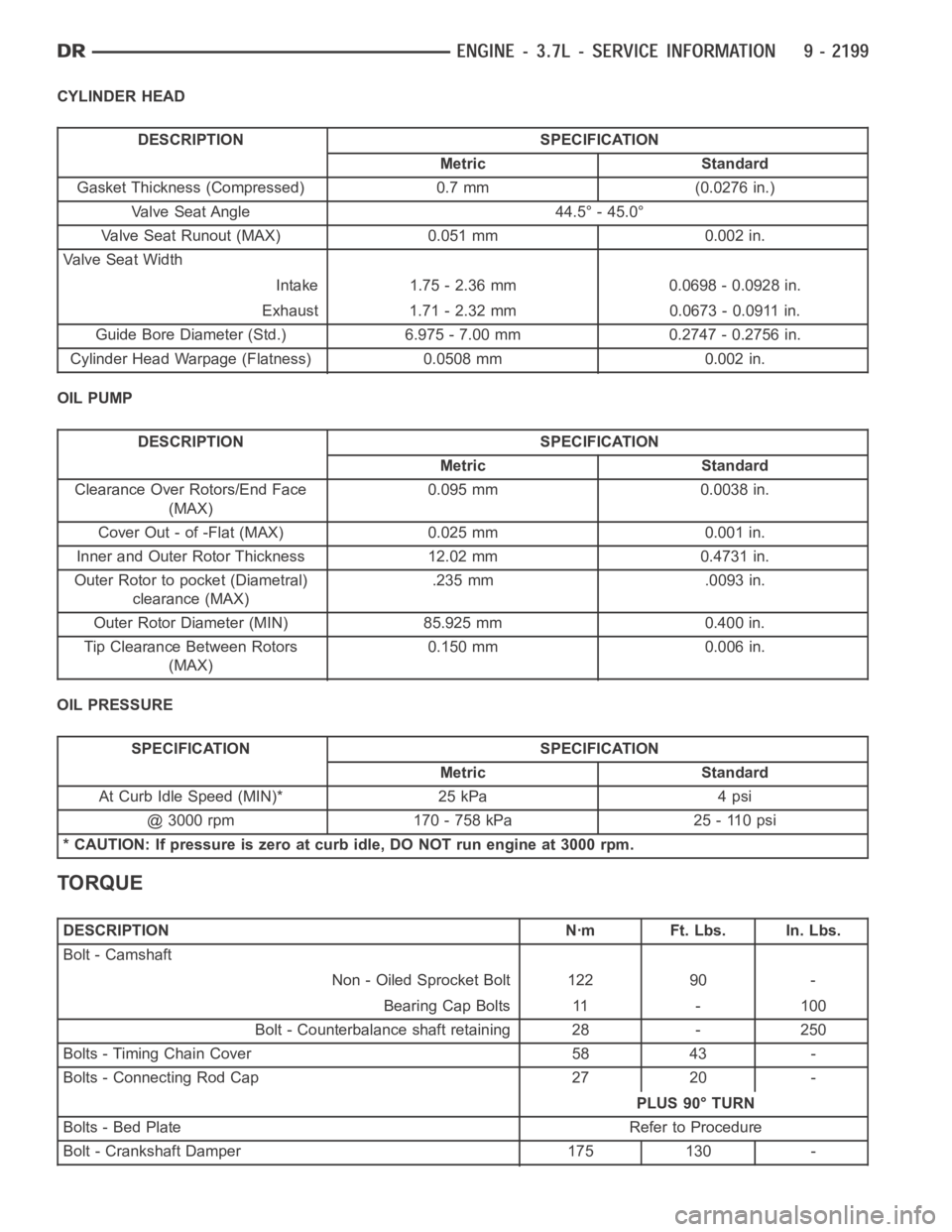
CYLINDER HEAD
DESCRIPTION SPECIFICATION
Metric Standard
Gasket Thickness (Compressed) 0.7 mm (0.0276 in.)
Valve Seat Angle 44.5° - 45.0°
Valve Seat Runout (MAX) 0.051 mm 0.002 in.
Va l v e S e a t W i d t h
Intake 1.75 - 2.36 mm 0.0698 - 0.0928 in.
Exhaust 1.71 - 2.32 mm 0.0673 - 0.0911 in.
Guide Bore Diameter (Std.) 6.975 - 7.00 mm 0.2747 - 0.2756 in.
Cylinder Head Warpage (Flatness) 0.0508 mm 0.002 in.
OIL PUMP
DESCRIPTION SPECIFICATION
Metric Standard
Clearance Over Rotors/End Face
(MAX)0.095 mm 0.0038 in.
Cover Out - of -Flat (MAX) 0.025 mm 0.001 in.
Inner and Outer Rotor Thickness 12.02 mm 0.4731 in.
Outer Rotor to pocket (Diametral)
clearance (MAX).235 mm .0093 in.
Outer Rotor Diameter (MIN) 85.925 mm 0.400 in.
Tip Clearance Between Rotors
(MAX)0.150 mm 0.006 in.
OIL PRESSURE
SPECIFICATION SPECIFICATION
Metric Standard
At Curb Idle Speed (MIN)* 25 kPa 4 psi
@ 3000 rpm 170 - 758 kPa 25 - 110 psi
* CAUTION: If pressure is zero at curb idle, DO NOT run engine at 3000 rpm.
TORQUE
DESCRIPTION Nꞏm Ft. Lbs. In. Lbs.
Bolt - Camshaft
Non - Oiled Sprocket Bolt 122 90 -
Bearing Cap Bolts 11 - 100
Bolt - Counterbalance shaft retaining 28 - 250
Bolts - Timing Chain Cover 58 43 -
Bolts - Connecting Rod Cap 27 20 -
PLUS 90° TURN
Bolts - Bed Plate Refer to Procedure
Bolt - Crankshaft Damper 175 130 -
Page 1514 of 5267
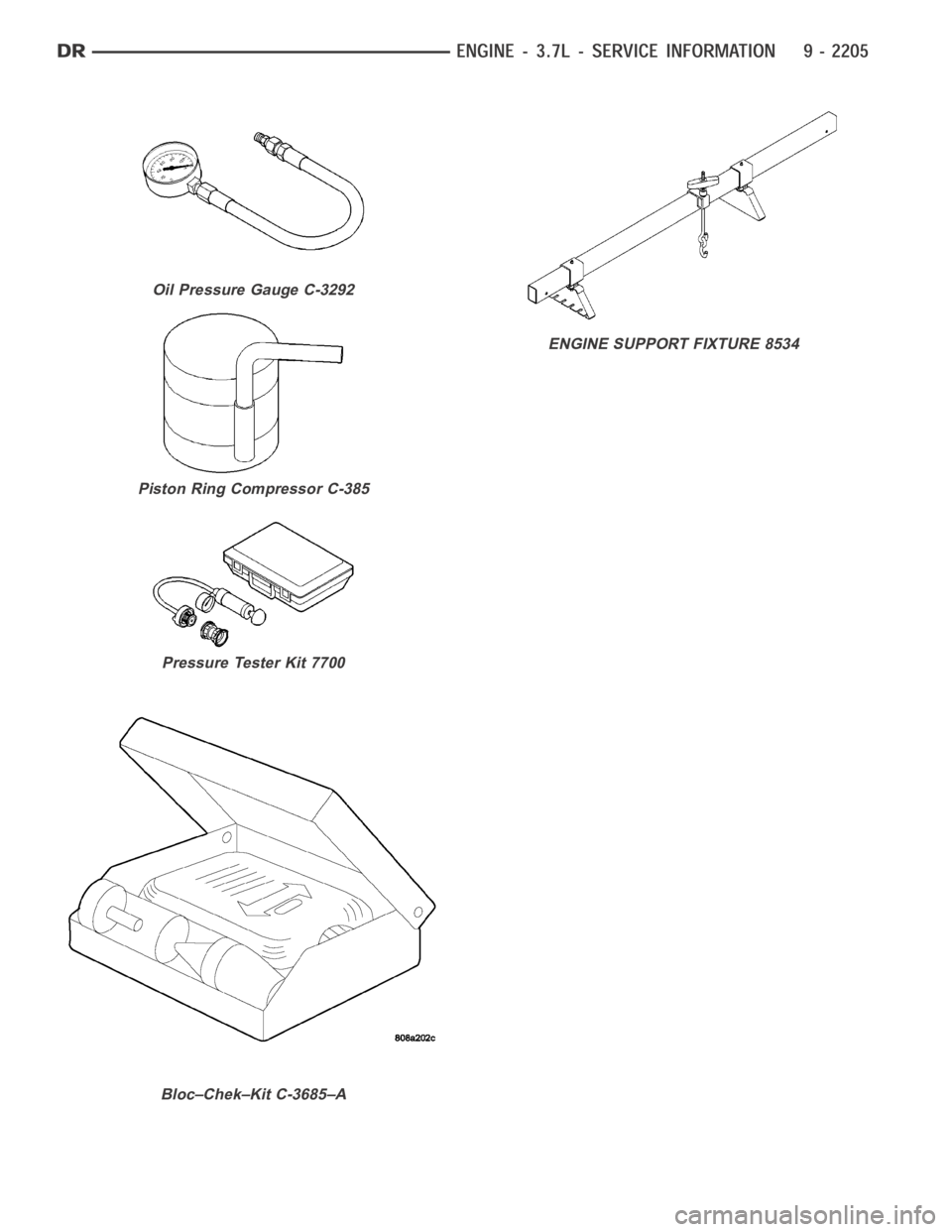
Oil Pressure Gauge C-3292
Piston Ring Compressor C-385
Pressure Tester Kit 7700
Bloc–Chek–Kit C-3685–A
ENGINE SUPPORT FIXTURE 8534
Page 1536 of 5267
HEAD-CYLINDER-RIGHT
DIAGNOSIS AND TESTING - HYDRAULIC LASH ADJUSTER
A tappet-like noise may be produced from several items. Check the followingitems.
1. Engine oil level too high or too low. This may cause aerated oil to enter the adjusters and cause them to be
spongy.
2. Insufficient running time after rebuilding cylinder head. Low speed runningupto1hourmayberequired.
3. Turn engine off and let set for a few minutes before restarting. Repeat this several times after engine has
reached normal operating temperature.
4. Low oil pressure.
5. The oil restrictor in cylinder head gasket or the oil passage to the cylinder head is plugged with debris.
6. Airingestedintooilduetobrokenorcrackedoilpumppickup.
7. Worn valve guides.
8. Rocker arm ears contacting valve spring retainer.
9. Rocker arm loose, adjuster stuck or at maximum extension and still leaves lash in the system.
10. Oil leak or excessive cam bore wear in cylinder head.
11. Faulty lash adjuster.
a. Check lash adjusters for sponginess while installed in cylinder head and cam on camshaft at base circle.
Depress part of rocker arm over adjuster. Normal adjusters should feel firm when pressed quickly. When pressed
very slowly, lash adjusters should collapse.
b. Remove suspected lash adjusters, and replace.
c. Before installation, make sure adjusters are full of oil. This can be verified by little plunger travel when lash
adjuster is depressed quickly.
REMOVAL
REMOVAL RIGHT CYLINDER HEAD
1. Disconnect battery negative cable.
2. Raise the vehicle on a hoist.
3. Disconnect the exhaust pipe at the right side
exhaust manifold.
4. Drain the engine coolant (Refer to 7 - COOLING -
STANDARD PROCEDURE).
5. Lower the vehicle.
6. Remove the intake manifold (Refer to 9 - ENGINE/
MANIFOLDS/INTAKE MANIFOLD - REMOVAL).
7. Remove the cylinder head cover (Refer to 9 -
ENGINE/CYLINDER HEAD - REMOVAL).
8. Remove the fan shroud (Refer to 7 - COOLING/
ENGINE/RADIATOR FAN - REMOVAL).
9. Remove oil fill housing from cylinder head.
10. Remove accessory drive belt (Refer to 7 - COOL-
ING/ACCESSORY DRIVE/DRIVE BELTS -
REMOVAL).
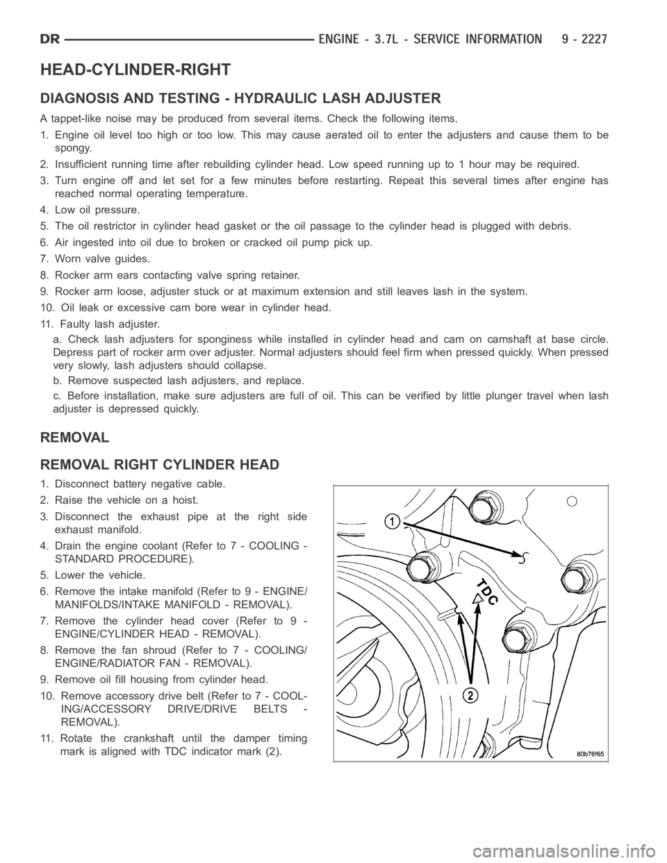
11. Rotate the crankshaft until the damper timing
mark is aligned with TDC indicator mark (2).
Page 1585 of 5267
LUBRICATION
DESCRIPTION
The lubrication system is a full flow filtration pressure feed type.
OPERATION
Engine Lubrication Flow Chart - Block: Table 1
FROM TO
Oil Pickup Tube Oil Pump
Oil Pump Oil Filter
Oil Filter Block Main Oil Gallery
Block Main Oil Gallery 1. Crankshaft Main Journal
2. Left Cylinder Head*
3. Right Cylinder Head*
4. Counterbalance Shaft Rear Journal
Crankshaft Main Journals Crankshaft Rod Journals
Crankshaft Number One Main Journal 1. Front Timing Chain Idler Shaft
2. Counterbalance Shaft - Front Journal
3. Both Secondary Chain Tensioners
Left Cylinder Head Refer to Engine Lubrication Flow Chart - Cylinder
Heads: Table 2
Right Cylinder Head Refer to Engine Lubrication Flow Chart - Cylinder
Heads: Table 2
* The cylinder head gaskets have an oil restricter to control oil flow to thecylinder heads
Engine Lubrication Flow Chart - Cylinder Heads: Table 2
FROM TO
Cylinder Head Oil Port (in bolt hole) Diagonal Cross Drilling to Main Oil Gallery
Main Oil Gallery (drilled through head from rear to front) 1. Base of Camshaft Towers
2. Lash Adjuster Towers
Base of Camshaft Towers Vertical Drilling Through Tower to Camshaft Bearings**
Lash Adjuster Towers Diagonal Drillings to Hydraulic Lash Adjuster Pockets
** The number three camshaft bearing journal feeds oil into the hollow camshaft tubes. Oil is routed to the intake
lobes, which have oil passages drilled into them to lubricate the rocker arms.
Page 1586 of 5267
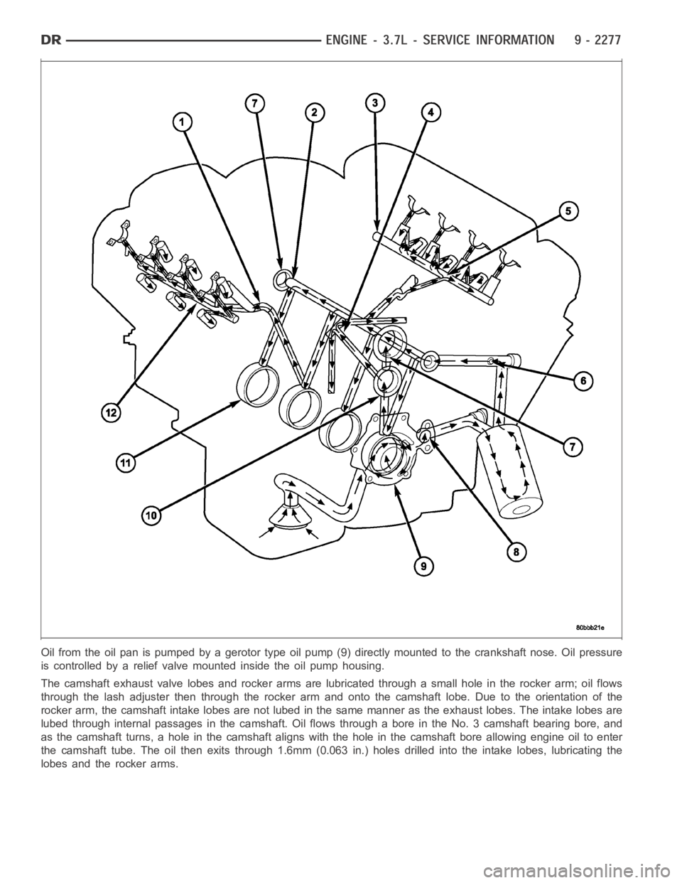
Oil from the oil pan is pumped by a gerotor type oil pump (9) directly mountedto the crankshaft nose. Oil pressure
is controlled by a relief valve mounted inside the oil pump housing.
The camshaft exhaust valve lobes and rocker arms are lubricated through a small hole in the rocker arm; oil flows
through the lash adjuster then through the rocker arm and onto the camshaftlobe. Due to the orientation of the
rocker arm, the camshaft intake lobes are not lubed in the same manner as theexhaust lobes. The intake lobes are
lubed through internal passages in the camshaft. Oil flows through a bore in the No. 3 camshaft bearing bore, and
as the camshaft turns, a hole in the camshaft aligns with the hole in the camshaft bore allowing engine oil to enter
the camshaft tube. The oil then exits through 1.6mm (0.063 in.) holes drilled into the intake lobes, lubricating the
lobes and the rocker arms.
Page 1587 of 5267
DIAGNOSIS AND TESTING
DIAGNOSIS AND TESTING - ENGINE OIL LEAK
Begin with a thorough visual inspection of the engine, particularly at thearea of the suspected leak. If an oil leak
source is not readily identifiable, thefollowingstepsshouldbefollowed:
1. Do not clean or degrease the engine at this time because some solvents maycause rubber to swell, temporarily
stopping the leak.
2. Add an oil soluble dye (use as recommended by manufacturer). Start the engine and let idle for approximately 15
minutes. Check the oil dipstick to make sure the dye is thoroughly mixed as indicated with a bright yellow color
under a black light.
3. Using a black light, inspect the entire engine for fluorescent dye, particularly at the suspected area of oil leak. If
the oil leak is found and identified, repair per service manual instructions.
4. If dye is not observed, drive the vehicle at various speeds for approximately 24 km (15 miles), and repeat inspec-
tion.If the oil leak source is not positively identified at this time, proceed with the air leak detection test method.
Air Leak Detection Test Method
1. Disconnect the breather cap to air cleaner hose at the breather cap end. Cap or plug breather cap nipple.
2. Remove the PCV valve from the cylinder head cover. Cap or plug the PCV valvegrommet.
3. Attach an air hose with pressure gauge and regulator to the dipstick tube.
CAUTION: Do not subject the engine assembly to more than 20.6 kPa (3 PSI) of test pressure.
4. Gradually apply air pressure from 1 psi to 2.5 psi maximum while applyingsoapy water at the suspected source.
Adjust the regulator to the suitable test pressure that provide the best bubbles which will pinpoint the leak
source. If the oil leak is detected and identified, repair per service manual procedures.
5. If the leakage occurs at the rear oil seal area, refer to the section, Inspection for Rear Seal Area Leak.
6. If no leaks are detected, turn off the air supply and remove the air hose and all plugs and caps. Install the PCV
valve and breather cap hose.
7. Clean the oil off the suspect oil leak area using a suitable solvent. Drive the vehicle at various speeds approx-
imately 24 km (15 miles). Inspect the engine for signs of an oil leak by usinga black light.
INSPECTION FOR REAR SEAL AREA LEAKS
Since it is sometimes difficult to determine the source of an oil leak in therear seal area of the engine, a more
involved inspection is necessary. The following steps should be followedto help pinpoint the source of the leak.
If the leakage occurs at the crankshaft rear oil seal area:
1. Disconnect the battery.
2. Raise the vehicle.
3. Remove torque converter or clutch housing cover and inspect rear of block for evidence of oil. Use a black light
to check for the oil leak:
a. Circular spray pattern generally indicates seal leakage or crankshaftdamage.
b. Where leakage tends to run straight down, possible causes are a porous block, oil galley pipe plugs, oil filter
runoff, and main bearing cap to cylinder block mating surfaces.
4. If no leaks are detected, pressurize the crankcase as outlined in the, Inspection (Engine oil Leaks in general)
CAUTION: Do not exceed 20.6 kPa (3 psi).
5. If the leak is not detected, very slowly turn the crankshaft and watch forleakage. If a leak is detected between
the crankshaft and seal while slowly turning the crankshaft, it is possible the crankshaft seal surface is damaged.
The seal area on the crankshaft could have minor nicks or scratches that canbe polished out with emery cloth.
CAUTION: Use extreme caution when crankshaft polishing is necessary to remove minor nicks and
scratches. The crankshaft seal flange is especially machined to complement the function of the rear oil seal.
6. For bubbles that remain steady with shaft rotation, no further inspection can be done until disassembled.
Page 1588 of 5267
DIAGNOSIS AND TESTING - CHECKING ENGINE OIL PRESSURE
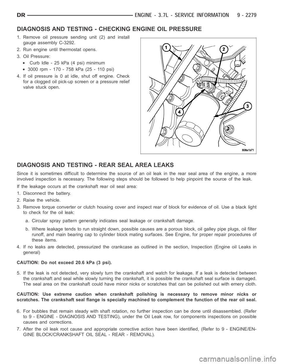
1. Remove oil pressure sending unit (2) and install
gauge assembly C-3292.
2. Run engine until thermostat opens.
3. Oil Pressure:
Curb Idle - 25 kPa (4 psi) minimum
3000 rpm - 170 - 758 kPa (25 - 110 psi)
4. If oil pressure is 0 at idle, shut off engine. Check
for a clogged oil pick-up screen or a pressure relief
valve stuck open.
DIAGNOSIS AND TESTING - REAR SEAL AREA LEAKS
Since it is sometimes difficult to determine the source of an oil leak in therear seal area of the engine, a more
involved inspection is necessary. The following steps should be followedto help pinpoint the source of the leak.
If the leakage occurs at the crankshaft rear oil seal area:
1. Disconnect the battery.
2. Raise the vehicle.
3. Remove torque converter or clutch housing cover and inspect rear of block for evidence of oil. Use a black light
to check for the oil leak:
a. Circular spray pattern generally indicates seal leakage or crankshaftdamage.
b. Where leakage tends to run straight down, possible causes are a porous block, oil galley pipe plugs, oil filter
runoff, and main bearing cap to cylinder block mating surfaces. See Engine, for proper repair procedures of
these items.
4. If no leaks are detected, pressurized the crankcase as outlined in the section, Inspection (Engine oil Leaks in
general)
CAUTION: Do not exceed 20.6 kPa (3 psi).
5. If the leak is not detected, very slowly turn the crankshaft and watch forleakage. If a leak is detected between
the crankshaft and seal while slowly turning the crankshaft, it is possible the crankshaft seal surface is damaged.
The seal area on the crankshaft could have minor nicks or scratches that canbe polished out with emery cloth.
CAUTION: Use extreme caution when crankshaft polishing is necessary to remove minor nicks or
scratches. The crankshaft seal flange is specially machined to complement the function of the rear oil seal.
6. For bubbles that remain steady with shaft rotation, no further inspection can be done until disassembled. (Refer
to 9 - ENGINE - DIAGNOSIS AND TESTING), under the Oil Leak row, for components inspections on possible
causes and corrections.
7. After the oil leak root cause and appropriate corrective action have been identified, (Refer to 9 - ENGINE/EN-
GINE BLOCK/CRANKSHAFT OIL SEAL - REAR - REMOVAL).