2006 DODGE RAM SRT-10 oil pressure
[x] Cancel search: oil pressurePage 1067 of 5267
Theory of Operation
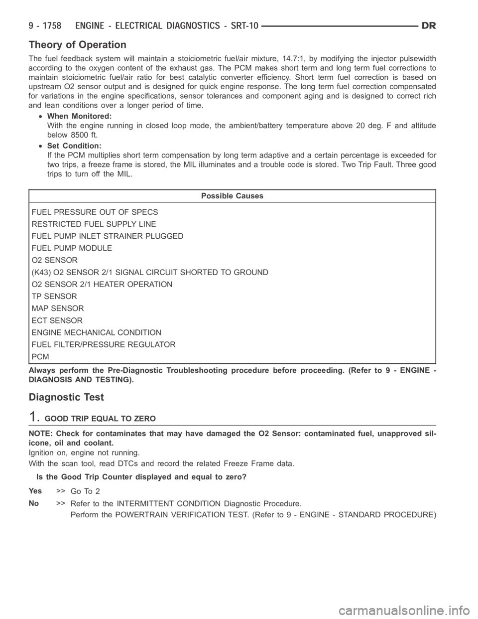
The fuel feedback system will maintain a stoiciometric fuel/air mixture,14.7:1, by modifying the injector pulsewidth
according to the oxygen content of the exhaust gas. The PCM makes short termand long term fuel corrections to
maintain stoiciometric fuel/air ratio for best catalytic converter efficiency. Short term fuel correction is based on
upstream O2 sensor output and is designed for quick engine response. The long term fuel correction compensated
for variations in the engine specifications, sensor tolerances and component aging and is designed to correct rich
and lean conditions over a longer period of time.
When Monitored:
With the engine running in closed loop mode, the ambient/battery temperature above 20 deg. F and altitude
below 8500 ft.
Set Condition:
If the PCM multiplies short term compensation by long term adaptive and a certain percentage is exceeded for
two trips, a freeze frame is stored, the MIL illuminates and a trouble code is stored. Two Trip Fault. Three good
trips to turn off the MIL.
Possible Causes
FUEL PRESSURE OUT OF SPECS
RESTRICTED FUEL SUPPLY LINE
FUEL PUMP INLET STRAINER PLUGGED
FUEL PUMP MODULE
O2 SENSOR
(K43) O2 SENSOR 2/1 SIGNAL CIRCUIT SHORTED TO GROUND
O2 SENSOR 2/1 HEATER OPERATION
TP SENSOR
MAP SENSOR
ECT SENSOR
ENGINE MECHANICAL CONDITION
FUEL FILTER/PRESSURE REGULATOR
PCM
Always perform the Pre-Diagnostic Troubleshooting procedure before proceeding. (Refer to 9 - ENGINE -
DIAGNOSIS AND TESTING).
Diagnostic Test
1.GOOD TRIP EQUAL TO ZERO
NOTE: Check for contaminates that may have damaged the O2 Sensor: contaminated fuel, unapproved sil-
icone, oil and coolant.
Ignition on, engine not running.
With the scan tool, read DTCs and record the related Freeze Frame data.
Is the Good Trip Counter displayed and equal to zero?
Ye s>>
Go To 2
No>>
Refer to the INTERMITTENT CONDITION Diagnostic Procedure.
Perform the POWERTRAIN VERIFICATION TEST. (Refer to 9 - ENGINE - STANDARD PROCEDURE)
Page 1074 of 5267

Theory of Operation
The fuel feedback system will maintain a stoiciometric fuel/air mixture,14.7:1, by modifying the injector pulsewidth
according to the oxygen content of the exhaust gas. The PCM makes short termand long term fuel corrections to
maintain stoiciometric fuel/air ratio for best catalytic converter efficiency. Short term fuel correction is based on
upstream O2 sensor output and is designed for quick engine response. The long term fuel correction compensated
for variations in the engine specifications, sensor tolerances and component aging and is designed to correct rich
and lean conditions over a longer period of time.
When Monitored:
With the engine running in closed loop mode, the ambient/battery temperature above 20 deg. F and altitude
below 8500 ft.
Set Condition:
If the PCM multiplies short term compensation by long term adaptive and a purge fuel multiplier and the result
is below a certain value for 30 seconds over two trips, a freeze frame is stored, the MIL illuminates and a
trouble code is stored. Two Trip Fault. Three good trips to turn off the MIL.
Possible Causes
O2 SENSOR
(K43) O2 SENSOR 2/1 SIGNAL CIRCUIT OPEN
(K43) O2 SENSOR 2/1 SIGNAL CIRCUIT SHORTED TO VOLTAGE
2/1 O2 SENSOR HEATER OPERATION
EVAP SYSTEM OPERATION
TP SENSOR VOLTAGE GREATER THAN 0.92 OF A VOLT WITH THROTTLE CLOSED
TP SENSOR
FUEL FILTER/PRESSURE REGULATOR
MAP SENSOR
ECT SENSOR
ENGINE MECHANICAL CONDITION
PCM
Always perform the Pre-Diagnostic Troubleshooting procedure before proceeding. (Refer to 9 - ENGINE -
DIAGNOSIS AND TESTING).
Diagnostic Test
1.GOOD TRIP EQUAL TO ZERO
NOTE: Check for contaminates that may have damaged the O2 Sensor: contaminated fuel, unapproved sil-
icone, oil and coolant.
Ignition on, engine not running.
With the scan tool, read DTCs and record the related Freeze Frame data.
NOTE: Any O2 Sensor, TPS, ECT, MAP, or EVAP DTCs must be repaired before continuing.
Is the Good Trip Counter displayed and equal to zero?
Ye s>>
Go To 2
No>>
Refer to the INTERMITTENT CONDITIONSymptom (Diagnostic Procedure).
Perform the POWERTRAIN VERIFICATION TEST. (Refer to 9 - ENGINE - STANDARD PROCEDURE)
Page 1126 of 5267
P0300-MULTIPLE CYLINDER MISFIRE
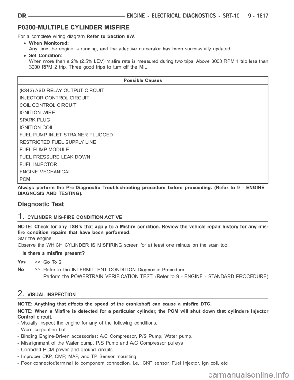
For a complete wiring diagramRefer to Section 8W.
When Monitored:
Any time the engine is running, and the adaptive numerator has been successfully updated.
Set Condition:
When more than a 2% (2.5% LEV) misfire rate is measured during two trips. Above 3000 RPM 1 trip less than
3000 RPM 2 trip. Three good trips to turn off the MIL.
Possible Causes
(K342) ASD RELAY OUTPUT CIRCUIT
INJECTOR CONTROL CIRCUIT
COIL CONTROL CIRCUIT
IGNITION WIRE
SPARK PLUG
IGNITION COIL
FUEL PUMP INLET STRAINER PLUGGED
RESTRICTED FUEL SUPPLY LINE
FUEL PUMP MODULE
FUEL PRESSURE LEAK DOWN
FUEL INJECTOR
ENGINE MECHANICAL
PCM
Always perform the Pre-Diagnostic Troubleshooting procedure before proceeding. (Refer to 9 - ENGINE -
DIAGNOSIS AND TESTING).
Diagnostic Test
1.CYLINDER MIS-FIRE CONDITION ACTIVE
NOTE: Check for any TSB’s that apply to a Misfire condition. Review the vehicle repair history for any mis-
fire condition repairs that have been performed.
Star the engine.
Observe the WHICH CYLINDER IS MISFIRING screen for at least one minute on the scan tool.
Is there a misfire present?
Ye s>>
Go To 2
No>>
Refer to the INTERMITTENT CONDITION Diagnostic Procedure.
Perform the POWERTRAIN VERIFICATION TEST. (Refer to 9 - ENGINE - STANDARD PROCEDURE)
2.VISUAL INSPECTION
NOTE: Anything that affects the speed of the crankshaft can cause a misfireDTC.
NOTE: When a Misfire is detected for a particular cylinder, the PCM will shut down that cylinders Injector
Control circuit.
- Visually inspect the engine for any of the following conditions.
- Worn serpentine belt
- Binding Engine-Driven accessories: A/C Compressor, P/S Pump, Water pump.
- Misalignment of the Water pump, P/S Pump and A/C Compressor pulleys
- Corroded PCM power and ground circuits.
- Improper CKP, CMP, MAP, and TP Sensor mounting
- Poor connector/terminal to component connection. i.e., CKP sensor, Fuel Injector, Ign coil, etc.
Page 1133 of 5267
When Monitored:
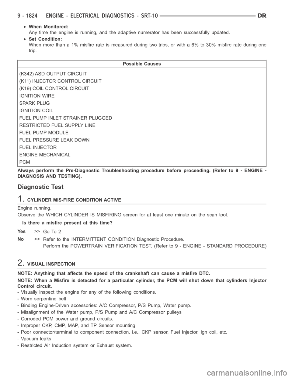
Any time the engine is running, and the adaptive numerator has been successfully updated.
Set Condition:
When more than a 1% misfire rate is measured during two trips, or with a 6% to 30% misfire rate during one
trip.
Possible Causes
(K342) ASD OUTPUT CIRCUIT
(K11) INJECTOR CONTROL CIRCUIT
(K19) COIL CONTROL CIRCUIT
IGNITION WIRE
SPARK PLUG
IGNITION COIL
FUEL PUMP INLET STRAINER PLUGGED
RESTRICTED FUEL SUPPLY LINE
FUEL PUMP MODULE
FUEL PRESSURE LEAK DOWN
FUEL INJECTOR
ENGINE MECHANICAL
PCM
Always perform the Pre-Diagnostic Troubleshooting procedure before proceeding. (Refer to 9 - ENGINE -
DIAGNOSIS AND TESTING).
Diagnostic Test
1.CYLINDER MIS-FIRE CONDITION ACTIVE
Engine running.
Observe the WHICH CYLINDER IS MISFIRING screen for at least one minute on the scan tool.
Isthereamisfirepresentatthistime?
Ye s>>
Go To 2
No>>
Refer to the INTERMITTENT CONDITION Diagnostic Procedure.
Perform the POWERTRAIN VERIFICATION TEST. (Refer to 9 - ENGINE - STANDARD PROCEDURE)
2.VISUAL INSPECTION
NOTE: Anything that affects the speed of the crankshaft can cause a misfireDTC.
NOTE: When a Misfire is detected for a particular cylinder, the PCM will shut down that cylinders Injector
Control circuit.
- Visually inspect the engine for any of the following conditions.
- Worn serpentine belt
- Binding Engine-Driven accessories: A/C Compressor, P/S Pump, Water pump.
- Misalignment of the Water pump, P/S Pump and A/C Compressor pulleys
- Corroded PCM power and ground circuits.
- Improper CKP, CMP, MAP, and TP Sensor mounting
- Poor connector/terminal to component connection. i.e., CKP sensor, Fuel Injector, Ign coil, etc.
- Vacuum leaks
- Restricted Air Induction system or Exhaust system.
Page 1142 of 5267
When Monitored:
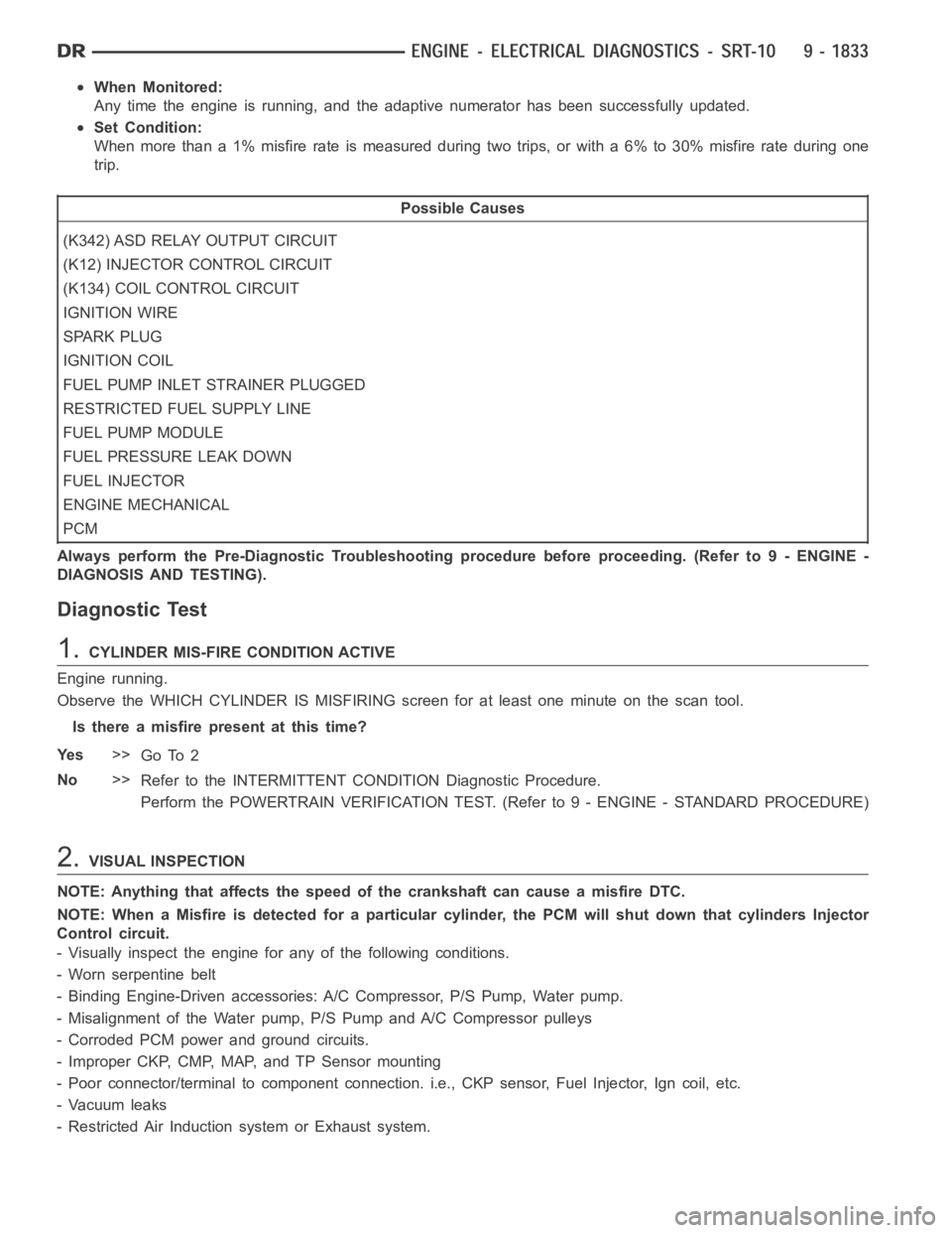
Any time the engine is running, and the adaptive numerator has been successfully updated.
Set Condition:
When more than a 1% misfire rate is measured during two trips, or with a 6% to 30% misfire rate during one
trip.
Possible Causes
(K342) ASD RELAY OUTPUT CIRCUIT
(K12) INJECTOR CONTROL CIRCUIT
(K134) COIL CONTROL CIRCUIT
IGNITION WIRE
SPARK PLUG
IGNITION COIL
FUEL PUMP INLET STRAINER PLUGGED
RESTRICTED FUEL SUPPLY LINE
FUEL PUMP MODULE
FUEL PRESSURE LEAK DOWN
FUEL INJECTOR
ENGINE MECHANICAL
PCM
Always perform the Pre-Diagnostic Troubleshooting procedure before proceeding. (Refer to 9 - ENGINE -
DIAGNOSIS AND TESTING).
Diagnostic Test
1.CYLINDER MIS-FIRE CONDITION ACTIVE
Engine running.
Observe the WHICH CYLINDER IS MISFIRING screen for at least one minute on the scan tool.
Isthereamisfirepresentatthistime?
Ye s>>
Go To 2
No>>
Refer to the INTERMITTENT CONDITION Diagnostic Procedure.
Perform the POWERTRAIN VERIFICATION TEST. (Refer to 9 - ENGINE - STANDARD PROCEDURE)
2.VISUAL INSPECTION
NOTE: Anything that affects the speed of the crankshaft can cause a misfireDTC.
NOTE: When a Misfire is detected for a particular cylinder, the PCM will shut down that cylinders Injector
Control circuit.
- Visually inspect the engine for any of the following conditions.
- Worn serpentine belt
- Binding Engine-Driven accessories: A/C Compressor, P/S Pump, Water pump.
- Misalignment of the Water pump, P/S Pump and A/C Compressor pulleys
- Corroded PCM power and ground circuits.
- Improper CKP, CMP, MAP, and TP Sensor mounting
- Poor connector/terminal to component connection. i.e., CKP sensor, Fuel Injector, Ign coil, etc.
- Vacuum leaks
- Restricted Air Induction system or Exhaust system.
Page 1151 of 5267
When Monitored:
Any time the engine is running, and the adaptive numerator has been successfully updated.
Set Condition:
When more than a 1% misfire rate is measured during two trips, or with a 6% to 30% misfire rate during one
trip.
Possible Causes
(K342) ASD RELAY OUTPUT CIRCUIT
(K13) INJECTOR CONTROL CIRCUIT
(K134) COIL CONTROL CIRCUIT
IGNITION WIRE
SPARK PLUG
IGNITION COIL
FUEL PUMP INLET STRAINER PLUGGED
RESTRICTED FUEL SUPPLY LINE
FUEL PUMP MODULE
FUEL PRESSURE LEAK DOWN
FUEL INJECTOR
ENGINE MECHANICAL
PCM
Always perform the Pre-Diagnostic Troubleshooting procedure before proceeding. (Refer to 9 - ENGINE -
DIAGNOSIS AND TESTING).
Diagnostic Test
1.CYLINDER MIS-FIRE CONDITION ACTIVE
Engine running.
Observe the WHICH CYLINDER IS MISFIRING screen for at least one minute on the scan tool.
Isthereamisfirepresentatthistime?
Ye s>>
Go To 2
No>>
Refer to the INTERMITTENT CONDITION Diagnostic Procedure.
Perform the POWERTRAIN VERIFICATION TEST. (Refer to 9 - ENGINE - STANDARD PROCEDURE)
2.VISUAL INSPECTION
NOTE: Anything that affects the speed of the crankshaft can cause a misfireDTC.
NOTE: When a Misfire is detected for a particular cylinder, the PCM will shut down that cylinders Injector
Control circuit.
- Visually inspect the engine for any of the following conditions.
- Worn serpentine belt
- Binding Engine-Driven accessories: A/C Compressor, P/S Pump, Water pump.
- Misalignment of the Water pump, P/S Pump and A/C Compressor pulleys
- Corroded PCM power and ground circuits.
- Improper CKP, CMP, MAP, and TP Sensor mounting
- Poor connector/terminal to component connection. i.e., CKP sensor, Fuel Injector, Ign coil, etc.
- Vacuum leaks
- Restricted Air Induction system or Exhaust system.
Page 1160 of 5267
When Monitored:
Any time the engine is running, and the adaptive numerator has been successfully updated.
Set Condition:
When more than a 1% misfire rate is measured during two trips, or with a 6% to 30% misfire rate during one
trip.
Possible Causes
(K342) ASD RELAY OUTPUT CIRCUIT
(K14) INJECTOR CONTROL CIRCUIT
(K133) COIL CONTROL CIRCUIT
IGNITION WIRE
SPARK PLUG
IGNITION COIL
FUEL PUMP INLET STRAINER PLUGGED
RESTRICTED FUEL SUPPLY LINE
FUEL PUMP MODULE
FUEL PRESSURE LEAK DOWN
FUEL INJECTOR
ENGINE MECHANICAL
PCM
Always perform the Pre-Diagnostic Troubleshooting procedure before proceeding. (Refer to 9 - ENGINE -
DIAGNOSIS AND TESTING).
Diagnostic Test
1.CYLINDER MIS-FIRE CONDITION ACTIVE
Engine running.
Observe the WHICH CYLINDER IS MISFIRING screen for at least one minute on the scan tool.
Isthereamisfirepresentatthistime?
Ye s>>
Go To 2
No>>
Refer to the INTERMITTENT CONDITION Diagnostic Procedure.
Perform the POWERTRAIN VERIFICATION TEST. (Refer to 9 - ENGINE - STANDARD PROCEDURE)
2.VISUAL INSPECTION
NOTE: Anything that affects the speed of the crankshaft can cause a misfireDTC.
NOTE: When a Misfire is detected for a particular cylinder, the PCM will shut down that cylinders Injector
Control circuit.
- Visually inspect the engine for any of the following conditions.
- Worn serpentine belt
- Binding Engine-Driven accessories: A/C Compressor, P/S Pump, Water pump.
- Misalignment of the Water pump, P/S Pump and A/C Compressor pulleys
- Corroded PCM power and ground circuits.
- Improper CKP, CMP, MAP, and TP Sensor mounting
- Poor connector/terminal to component connection. i.e., CKP sensor, Fuel Injector, Ign coil, etc.
- Vacuum leaks
- Restricted Air Induction system or Exhaust system.
Page 1169 of 5267
When Monitored:
Any time the engine is running, and the adaptive numerator has been successfully updated.
Set Condition:
When more than a 1% misfire rate is measured during two trips, or with a 6% to 30% misfire rate during one
trip.
Possible Causes
(K342) ASD RELAY OUTPUT CIRCUIT
(K38) INJECTOR CONTROL CIRCUIT
(K17) COIL CONTROL CIRCUIT
IGNITION WIRE
SPARK PLUG
IGNITION COIL
FUEL PUMP INLET STRAINER PLUGGED
RESTRICTED FUEL SUPPLY LINE
FUEL PUMP MODULE
FUEL PRESSURE LEAK DOWN
FUEL INJECTOR
ENGINE MECHANICAL
PCM
Always perform the Pre-Diagnostic Troubleshooting procedure before proceeding. (Refer to 9 - ENGINE -
DIAGNOSIS AND TESTING).
Diagnostic Test
1.CYLINDER MIS-FIRE CONDITION ACTIVE
Engine running.
Observe the WHICH CYLINDER IS MISFIRING screen for at least one minute on the scan tool.
Isthereamisfirepresentatthistime?
Ye s>>
Go To 2
No>>
Refer to the INTERMITTENT CONDITION Diagnostic Procedure.
Perform the POWERTRAIN VERIFICATION TEST. (Refer to 9 - ENGINE - STANDARD PROCEDURE)
2.VISUAL INSPECTION
NOTE: Anything that affects the speed of the crankshaft can cause a misfireDTC.
NOTE: When a Misfire is detected for a particular cylinder, the PCM will shut down that cylinders Injector
Control circuit.
- Visually inspect the engine for any of the following conditions.
- Worn serpentine belt
- Binding Engine-Driven accessories: A/C Compressor, P/S Pump, Water pump.
- Misalignment of the Water pump, P/S Pump and A/C Compressor pulleys
- Corroded PCM power and ground circuits.
- Improper CKP, CMP, MAP, and TP Sensor mounting
- Poor connector/terminal to component connection. i.e., CKP sensor, Fuel Injector, Ign coil, etc.
- Vacuum leaks
- Restricted Air Induction system or Exhaust system.