2006 DODGE RAM SRT-10 oil pressure
[x] Cancel search: oil pressurePage 368 of 5267
For a complete wiring diagramRefer to Section 8W.
Theory of Operation
When all criteria has been met, power is supplied to each MDS Solenoid when the engine is making a transition
from 8 cylinder mode to 4 cylinder mode. By actuating the solenoid, oil pressure is raised to the pair of lifters that
coincide with each particular solenoid. The oil pressure pushes in the locking pins that allows the lifter to collapse,
decoupling the valves and camshaft.
When Monitored:
Transition from 8 to 4 cylinder mode.
Set Condition:
When the PCM recognizes a problem with the Solenoid Control circuit. One trip fault.
Possible Causes
(K452) MDS SOLENOID NO.4 CONTROL SHORT TO BATTERY VOLTAGE
(K452) MDS SOLENOID NO.4 CONTROL SHORT TO GROUND
(K452) MDS SOLENOID NO.4 CONTROL OPEN
(Z903) GROUND CIRCUIT OPEN
MDS SOLENOID NO.4
PCM
Always perform the Pre-Diagnostic Troubleshooting procedure before proceeding. (Refer to 9 - ENGINE -
DIAGNOSIS AND TESTING).
Diagnostic Test
1.ACTIVE DTC
Ignition on, engine not running.
With a scan tool, read DTCs.
Is the DTC active at this time?
Ye s>>
Go To 2
No>>
Refer to the INTERMITTENT CONDITION Diagnostic Procedure.
Perform the POWERTRAIN VERIFICATION TEST. (Refer to 9 - ENGINE - STANDARD PROCEDURE)
2.MDS SOLENOID NO.4
Turn the ignition off.
Gain access to the MDS Solenoid No. 4.
Disconnect the MDS Solenoid No.4 harness connector.
Ignition on, engine not running.
Turn off all accessories.
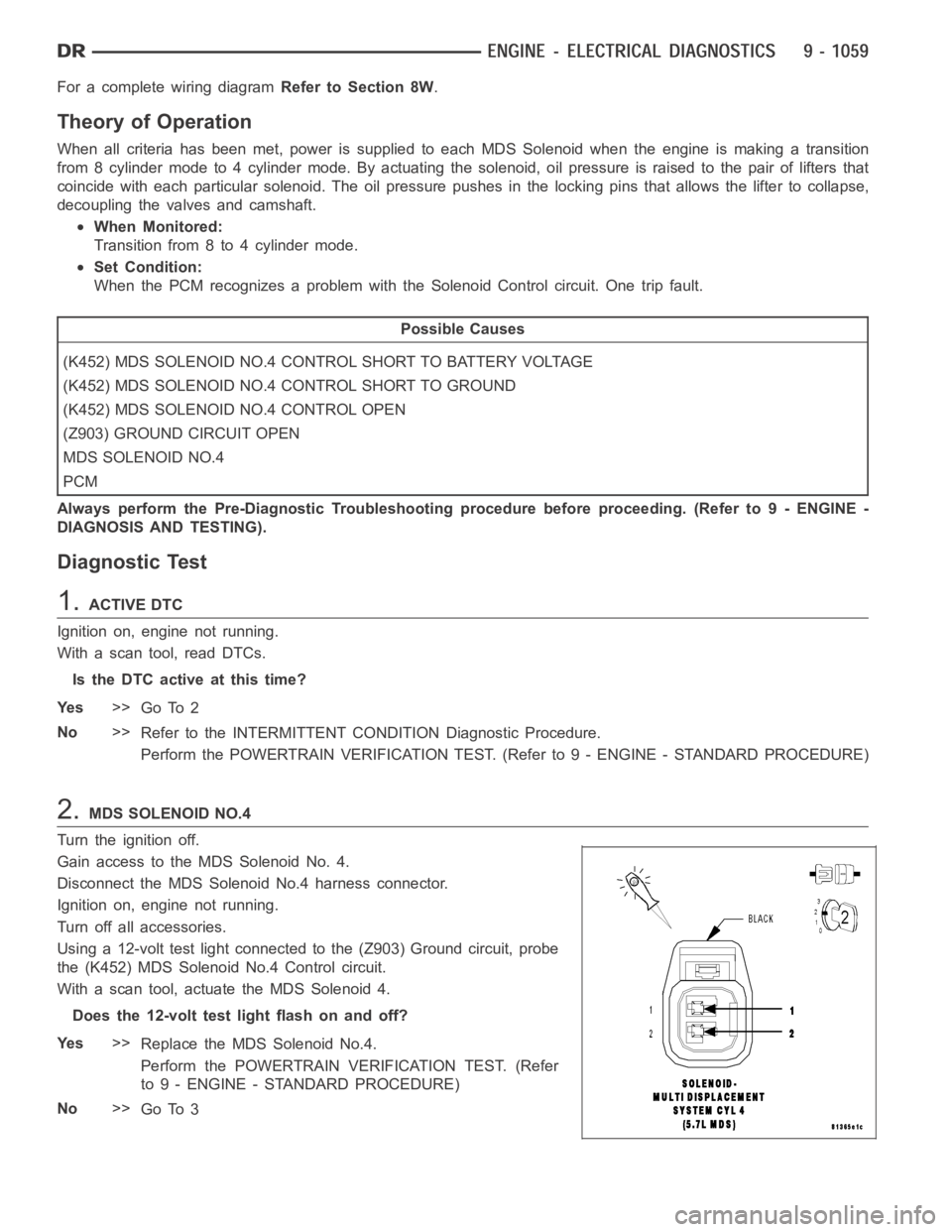
Using a 12-volt test light connected to the (Z903) Ground circuit, probe
the (K452) MDS Solenoid No.4 Control circuit.
With a scan tool, actuate the MDS Solenoid 4.
Does the 12-volt test light flash on and off?
Ye s>>
Replace the MDS Solenoid No.4.
Perform the POWERTRAIN VERIFICATION TEST. (Refer
to 9 - ENGINE - STANDARD PROCEDURE)
No>>
Go To 3
Page 372 of 5267
For a complete wiring diagramRefer to Section 8W.
Theory of Operation
When all criteria has been met, power is supplied to each MDS Solenoid when the engine is making a transition
from 8 cylinder mode to 4 cylinder mode. By actuating the solenoid, oil pressure is raised to the pair of lifters that
coincide with each particular solenoid. The oil pressure pushes in the locking pins that allows the lifter to collapse,
decoupling the valves and camshaft.
When Monitored:
Transition from 8 to 4 cylinder mode.
Set Condition:
The MDS fails to disengage for cylinder 4. One trip fault.
Possible Causes
(K452) MDS SOLENOID NO.4 CONTROL SHORT TO VOLTAGE
OIL PASSAGES RESTRICTED
LIFTER
MDS SOLENOID NO.4
PCM
Always perform the Pre-Diagnostic Troubleshooting procedure before proceeding. (Refer to 9 - ENGINE -
DIAGNOSIS AND TESTING).
Diagnostic Test
1.ACTIVE DTC
Ignition on, engine not running.
With a scan tool, read DTCs.
Is the DTC active at this time?
Ye s>>
Go To 2
No>>
Refer to the INTERMITTENT CONDITION Diagnostic Procedure.
Perform the POWERTRAIN VERIFICATION TEST. (Refer to 9 - ENGINE - STANDARD PROCEDURE)
2.MDS SOLENOID NO.4 CONTROL CIRCUIT
Turn the ignition off.
Disconnect the MDS Solenoid No.4 harness connector.
Ignition on, engine not running.
Turn off all accessories.
Using a 12-volt test light connected to ground, probe the (K452) MDS Solenoid No.4 Control circuit.
Does the 12-volt test light illuminate?
Ye s>>
Go To 3
No>>
Go To 4
Page 376 of 5267
For a complete wiring diagramRefer to Section 8W.
Theory of Operation
When all criteria has been met, power is supplied to each MDS Solenoid when the engine is making a transition
from 8 cylinder mode to 4 cylinder mode. By actuating the solenoid, oil pressure is raised to the pair of lifters that
coincide with each particular solenoid. The oil pressure pushes in the locking pins that allows the lifter to collapse,
decoupling the valves and camshaft.
When Monitored:
Transition from 8 to 4 cylinder mode.
Set Condition:
When the PCM recognizes a problem with the Solenoid Control circuit. One trip fault.
Possible Causes
(K453) MDS SOLENOID NO.6 CONTROL SHORT TO BATTERY VOLTAGE
(K453) MDS SOLENOID NO.6 CONTROL SHORT TO GROUND
(K453) MDS SOLENOID NO.6 CONTROL OPEN
(Z903) GROUND CIRCUIT OPEN
MDS SOLENOID NO.6
PCM
Always perform the Pre-Diagnostic Troubleshooting procedure before proceeding. (Refer to 9 - ENGINE -
DIAGNOSIS AND TESTING).
Diagnostic Test
1.ACTIVE DTC
Ignition on, engine not running.
With a scan tool, read DTCs.
Is the DTC active at this time?
Ye s>>
Go To 2
No>>
Refer to the INTERMITTENT CONDITION Diagnostic Procedure.
Perform the POWERTRAIN VERIFICATION TEST. (Refer to 9 - ENGINE - STANDARD PROCEDURE)
2.MDS SOLENOID NO.6
Turn the ignition off.
Gain access to the MDS Solenoid No.6.
Disconnect the MDS Solenoid No.6 harness connector.
Ignition on, engine not running.
Turn off all accessories.
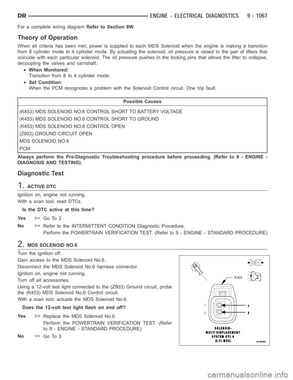
Using a 12-volt test light connected to the (Z903) Ground circuit, probe
the (K453) MDS Solenoid No.6 Control circuit.
With a scan tool, actuate the MDS Solenoid No.6.
Does the 12-volt test light flash on and off?
Ye s>>
Replace the MDS Solenoid No.6.
Perform the POWERTRAIN VERIFICATION TEST. (Refer
to 9 - ENGINE - STANDARD PROCEDURE)
No>>
Go To 3
Page 380 of 5267
For a complete wiring diagramRefer to Section 8W.
Theory of Operation
When all criteria has been met, power is supplied to each MDS Solenoid when the engine is making a transition
from 8 cylinder mode to 4 cylinder mode. By actuating the solenoid, oil pressure is raised to the pair of lifters that
coincide with each particular solenoid. The oil pressure pushes in the locking pins that allows the lifter to collapse,
decoupling the valves and camshaft.
When Monitored:
Transition from 8 to 4 cylinder mode.
Set Condition:
The MDS fails to disengage for cylinder 6. One trip fault.
Possible Causes
(K453) MDS SOLENOID NO.6 CONTROL SHORT TO VOLTAGE
OIL PASSAGES RESTRICTED
LIFTER
MDS SOLENOID NO.6
PCM
Always perform the Pre-Diagnostic Troubleshooting procedure before proceeding. (Refer to 9 - ENGINE -
DIAGNOSIS AND TESTING).
Diagnostic Test
1.ACTIVE DTC
Ignition on, engine not running.
With a scan tool, read DTCs.
Is the DTC active at this time?
Ye s>>
Go To 2
No>>
Refer to the INTERMITTENT CONDITION Diagnostic Procedure.
Perform the POWERTRAIN VERIFICATION TEST. (Refer to 9 - ENGINE - STANDARD PROCEDURE)
2.MDS SOLENOID NO.6 CONTROL CIRCUIT
Turn the ignition off.
Disconnect the MDS Solenoid No.6 harness connector.
Ignition on, engine not running.
Turn off all accessories.
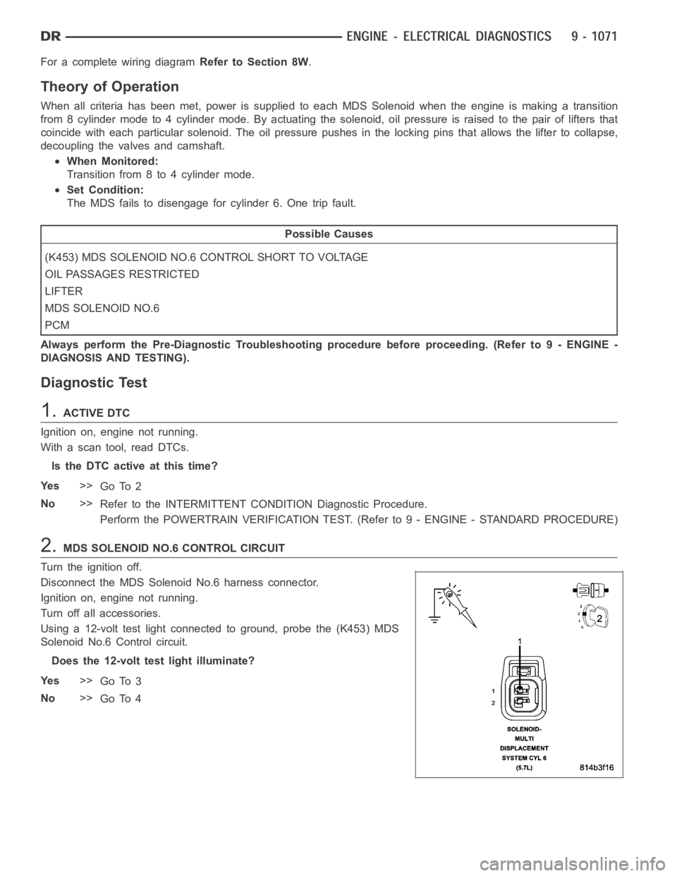
Using a 12-volt test light connected to ground, probe the (K453) MDS
Solenoid No.6 Control circuit.
Does the 12-volt test light illuminate?
Ye s>>
Go To 3
No>>
Go To 4
Page 384 of 5267
For a complete wiring diagramRefer to Section 8W.
Theory of Operation
When all criteria has been met, power is supplied to each MDS Solenoid when the engine is making a transition
from 8 cylinder mode to 4 cylinder mode. By actuating the solenoid, oil pressure is raised to the pair of lifters that
coincide with each particular solenoid. The oil pressure pushes in the locking pins that allows the lifter to collapse,
decoupling the valves and camshaft.
When Monitored:
Transition from 8 to 4 cylinder mode.
Set Condition:
When the PCM recognizes a problem with the Solenoid Control circuit. One trip fault.
Possible Causes
(K454) MDS SOLENOID NO.7 CONTROL SHORT TO BATTERY VOLTAGE
(K454) MDS SOLENOID NO.7 CONTROL SHORT TO GROUND
(K454) MDS SOLENOID NO.7 CONTROL OPEN
(Z903) GROUND CIRCUIT OPEN
MDS SOLENOID NO.7
PCM
Always perform the Pre-Diagnostic Troubleshooting procedure before proceeding. (Refer to 9 - ENGINE -
DIAGNOSIS AND TESTING).
Diagnostic Test
1.ACTIVE DTC
Ignition on, engine not running.
With a scan tool, read DTCs.
Is the DTC active at this time?
Ye s>>
Go To 2
No>>
Refer to the INTERMITTENT CONDITION Diagnostic Procedure.
Perform the POWERTRAIN VERIFICATION TEST. (Refer to 9 - ENGINE - STANDARD PROCEDURE)
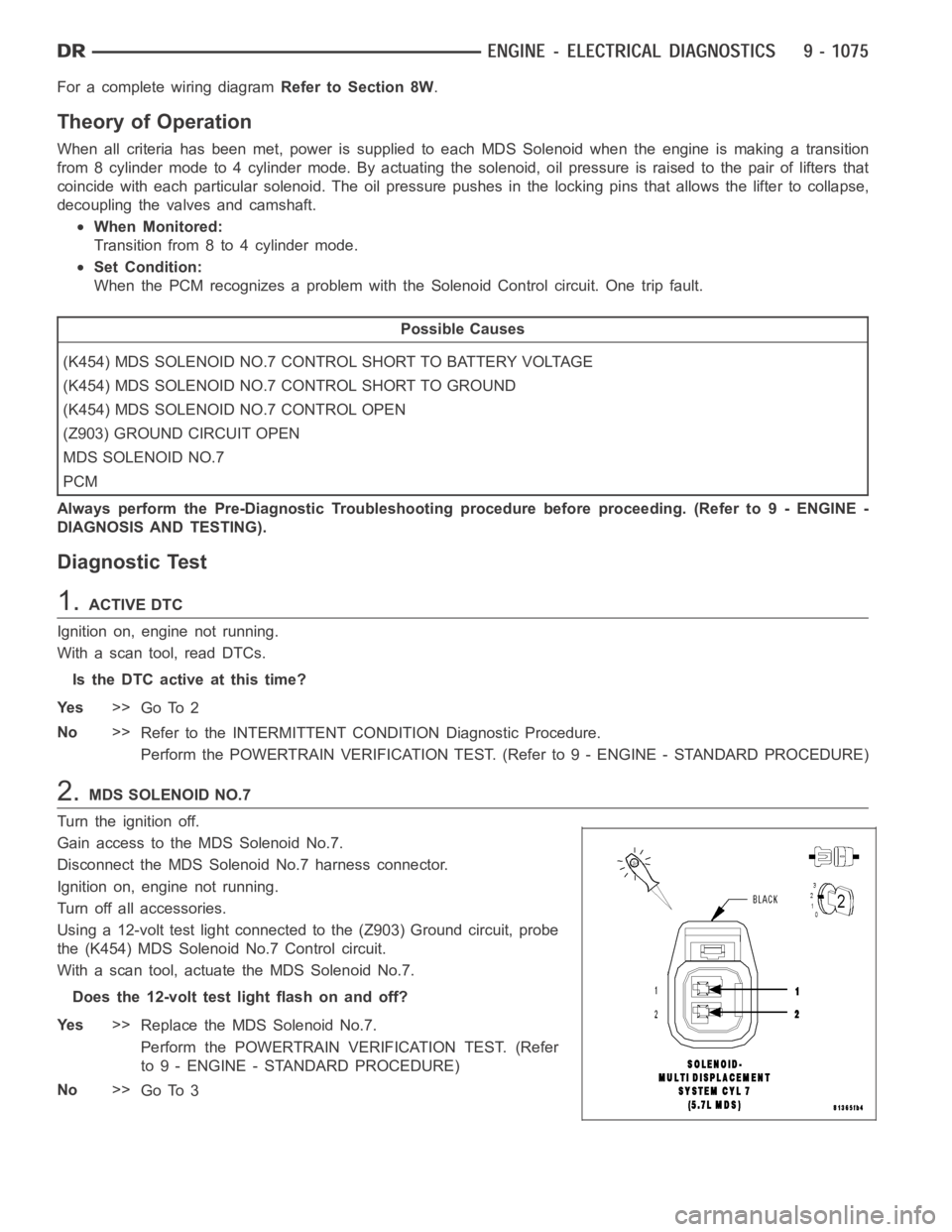
2.MDS SOLENOID NO.7
Turn the ignition off.
Gain access to the MDS Solenoid No.7.
Disconnect the MDS Solenoid No.7 harness connector.
Ignition on, engine not running.
Turn off all accessories.
Using a 12-volt test light connected to the (Z903) Ground circuit, probe
the (K454) MDS Solenoid No.7 Control circuit.
With a scan tool, actuate the MDS Solenoid No.7.
Does the 12-volt test light flash on and off?
Ye s>>
Replace the MDS Solenoid No.7.
Perform the POWERTRAIN VERIFICATION TEST. (Refer
to 9 - ENGINE - STANDARD PROCEDURE)
No>>
Go To 3
Page 388 of 5267
For a complete wiring diagramRefer to Section 8W.
Theory of Operation
When all criteria has been met, power is supplied to each MDS Solenoid when the engine is making a transition
from 8 cylinder mode to 4 cylinder mode. By actuating the solenoid, oil pressure is raised to the pair of lifters that
coincide with each particular solenoid. The oil pressure pushes in the locking pins that allows the lifter to collapse,
decoupling the valves and camshaft.
When Monitored:
Transition from 8 to 4 cylinder mode.
Set Condition:
The MDS fails to disengage for cylinder 7. Two trip fault.
Possible Causes
(K454) MDS SOLENOID NO.7 CONTROL SHORT TO VOLTAGE
OIL PASSAGES RESTRICTED
LIFTER
MDS SOLENOID NO.7
PCM
Always perform the Pre-Diagnostic Troubleshooting procedure before proceeding. (Refer to 9 - ENGINE -
DIAGNOSIS AND TESTING).
Diagnostic Test
1.ACTIVE DTC
Ignition on, engine not running.
With a scan tool, read DTCs.
Is the DTC active at this time?
Ye s>>
Go To 2
No>>
Refer to the INTERMITTENT CONDITION Diagnostic Procedure.
Perform the POWERTRAIN VERIFICATION TEST. (Refer to 9 - ENGINE - STANDARD PROCEDURE)
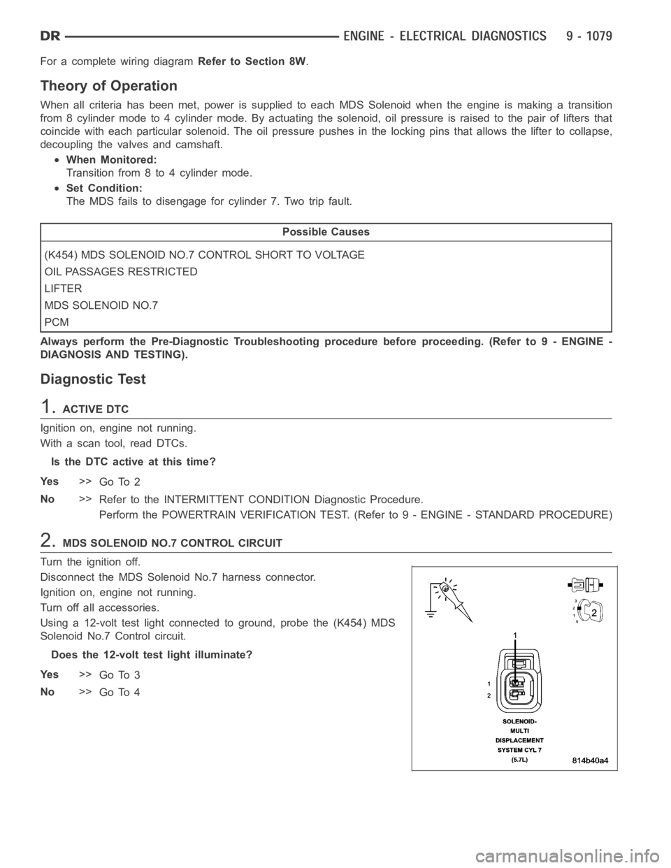
2.MDS SOLENOID NO.7 CONTROL CIRCUIT
Turn the ignition off.
Disconnect the MDS Solenoid No.7 harness connector.
Ignition on, engine not running.
Turn off all accessories.
Using a 12-volt test light connected to ground, probe the (K454) MDS
Solenoid No.7 Control circuit.
Does the 12-volt test light illuminate?
Ye s>>
Go To 3
No>>
Go To 4
Page 391 of 5267

P3497-MDS RATIONALITY BANK 2
For a complete wiring diagramRefer to Section 8W.
Theory of Operation
When all criteria has been met, power is supplied to each MDS Solenoid when the engine is making a transition
from 8 cylinder mode to 4 cylinder mode. By actuating the solenoid, oil pressure is raised to the pair of lifters that
coincide with each particular solenoid. The oil pressure pushes in the locking pins that allows the lifter to collapse,
decoupling the valves and camshaft.
When Monitored:
Transition from 8 to 4 cylinder mode.
Set Condition:
O2 sensor readings on Bank 2 side indicate a lean condition while in 4 cylinder mode. One trip fault.
Possible Causes
INSUFFICIENT OIL PRESSURE ACTING ON THE LIFTER LOCKING PINS
OIL PASSAGES RESTRICTED
LIFTER
MDS SOLENOID
Always perform the Pre-Diagnostic Troubleshooting procedure before proceeding (Refer to 9 - ENGINE -
DIAGNOSIS AND TESTING).
Diagnostic Test
1.ACTIVE DTC
Ignition on, engine not running.
With a scan tool, read DTCs.
NOTE: Diagnose any Oil Pressure DTCs before continuing.
Is the DTC active at this time?
Ye s>>
Go To 2
No>>
Refer to the INTERMITTENT CONDITION Diagnostic Procedure.
Perform the POWERTRAIN VERIFICATION TEST. (Refer to 9 - ENGINE - STANDARD PROCEDURE)
2.MDS SOLENOID 4
Turn the ignition off.
Remove the Intake Manifold per Service Information.
Turn the ignition on.
With the scan tool actuate the MDS Solenoid 4.
Can you feel and hear the Solenoid Actuating?
Ye s>>
Go To 3
No>>
Remove the Solenoid and check for any debris that may be blocking the oil passages to the Solenoid.
If the passages are clogged, clean the passages and replace the MDS Solenoid4.Ifthepassagesare
not clogged with debris, replace the MDS Solenoid 4.
Perform the POWERTRAIN VERIFICATION TEST. (Refer to 9 - ENGINE - STANDARD PROCEDURE)
Page 456 of 5267

P0478-HIGH VOLTAGE ON THE ENGINE
BRAKE DRIVER.......................... 1350
P0480-FAN CLUTCH ...................... 1352
P0483-FAN SPEED ....................... 1357
P0500-NO VEHICLE SPEED SENSOR
SIGNAL.................................. 1364
P0513-SKIM INVALID KEY ERROR ......... 1368
P0514-BAT TEMPERATURE SENSOR
RATIONALITY............................ 1370
P0516-LOW VOLTAGE AT THE BAT TEMP
SENSOR................................. 1372
P0517-HIGH VOLTAGE AT THE BAT TEMP
SENSOR................................. 1376
P0521-OIL PRESSURE SWITCH
RATIONALITY............................ 1380
P0524-OIL PRESSURE TOO LOW .......... 1383
P0532-A/C SENDING UNIT VOLTS TOO
LOW..................................... 1385
P0533-A/C SENDING UNIT VOLTS TOO
HIGH.................................... 1391
P0541-LOW VOLTAGE ON THE #1 INTAKE
AIR HEATER RELAY...................... 1396
P0542-HIGH VOLTAGE ON THE #1 INTAKE
AIR HEATER RELAY...................... 1399
P0562-BATTERY VOLTAGE LOW ........... 1402
P0563-BATTERY VOLTAGE HIGH .......... 1406
P0572-LOW VOLTAGE DETECTED AT THE
BRAKE SWITCH.......................... 1409
P0573-HIGH VOLTAGE DETECTED AT THE
BRAKE SWITCH.......................... 1413
P0580-LOW VOLTAGE DETECTED AT THE
SPEED CONTROL SWITCH................ 1416
P0581-HIGH VOLTAGE DETECTED AT THE
SPEED CONTROL SWITCH................ 1420
P0602-CHECKSUM ERROR ............... 1425
P0604-ECM SOFTWARE ERROR .......... 1426
P0606-ECM HARDWARE ERROR .......... 1427
P0607-ECM INTERNAL FAILURE ........... 1428
P0622-GENERATOR FIELD NOT
SWITCHING PROPERLY.................. 1429
P0628-LOW VOLTAGE DETECTED AT THE
FUEL LIFT PUMP......................... 1433
P0629-HIGH VOLTAGE DETECTED AT THE
FUEL LIFT PUMP......................... 1436
P0630-VIN NOT ENTERED ERROR ........ 1439
P0633-SKIM SECRET KEY NOT ENTERED . 1440
P0642-LOW VOLTAGE AT THE #2 SENSOR
SUPPLY CIRCUIT......................... 1441
P0643-HIGH VOLTAGE AT THE #2 SENSOR
SUPPLY CIRCUIT......................... 1445
P0646-LOW VOLTAGE DETECTED AT THE
A/C CLUTCH RELAY...................... 1448
P0647-HIGH VOLTAGE DETECTED AT THE
A/C CLUTCH RELAY...................... 1451
P0652-LOW VOLTAGE AT THE #1 SENSOR
SUPPLY CIRCUIT......................... 1454
P0653-HIGH VOLTAGE AT THE #1 SENSOR
SUPPLY CIRCUIT......................... 1458P0698-ACCELERATOR PEDAL POSITION
SENSOR (APPS) SUPPLY VOLTAGE TOO
LOW..................................... 1461
P0699-ACCELERATOR PEDAL POSITION
SENSOR (APPS) SUPPLY VOLTAGE TOO
HIGH.................................... 1465
P1272-A/C CLUTCH CONTROL CIRCUIT 2
LOW..................................... 1468
P1273-A/C CLUTCH CONTROL CIRCUIT 2
HIGH.................................... 1471
P1274-A/C CLUTCH CONTROL CIRCUIT 2
OPEN.................................... 1475
P1275-A/C CLUTCH CONTROL CIRCUIT 2
OVERCURRENT.......................... 1479
P127C-FUEL PUMP CONTROL CIRCUIT 2
LOW..................................... 1482
P127D-FUEL PUMP CONTROL CIRCUIT 2
HIGH.................................... 1485
P127E-FUEL PUMP CONTROL CIRCUIT 2
OPEN (TIPM)............................. 1489
P0127F-FUEL PUMP CONTROL CIRCUIT 2
OVERCURRENT (TIPM)
................... 1493
P1652-J1850 SHORT TO GROUND ......... 1496
P2121-PPS CONFORMANCE ERROR ...... 1499
P2122-PPS 1 VOLTAGE TOO LOW ......... 1511
P2123-PPS 1 VOLTAGE TOO HIGH ........ 1516
P2127-PPS 2 VOLTAGE TOO LOW ......... 1520
P2128-PPS 2 VOLTAGE TOO HIGH ........ 1525
P2146-BANK 1 (CYLINDERS 1-3) SHORTED
HIGH OR LOW........................... 1529
P2149-BANK 2 (CYLINDERS 4-6) SHORTED
HIGH OR LOW........................... 1537
P2266-WATER IN FUEL (WIF) SENSOR
VOLTAGE TOO LOW...................... 1544
P2269-WATER IN FUEL (WIF) .............. 1547
P2502-CHARGING SYSTEM ERROR ....... 1549
P2503-CHARGING SYSTEM OUTPUT LOW . 1552
P2504-CHARGING SYSTEM OUTPUT HIGH . 1555
P2509-POWERDOWN DATA LOST ERROR . 1559
P2607-LOW VOLTAGE AT THE #2 INTAKE
AIR HEATER RELAY...................... 1563
P2608-HIGH VOLTAGE AT THE #2 INTAKE
AIR HEATER RELAY...................... 1566
P2609-NO VOLTAGE DROP SEEN FROM
INTAKE AIR HEATERS.................... 1569
*CHECKING THE ACCELERATOR PEDAL
SENSOR CALIBRATION................... 1572
*CHECKING THE ECM POWER AND
GROUNDS............................... 1573
* PRESSURE LIMITING VALVE TEST ....... 1574
*ENGINE SURGES ........................ 1575
*ENGINE NO START/HARD START ......... 1578
*FUEL HEATER THERMOSTAT TEST ....... 1581
*IN-TANK FUEL LIFT PUMP FLOW/
DIAGNOSTIC TEST PROCEDURE.......... 1582
*FUEL PUMP RETURN FLOW TEST ........ 1585
*HIGH PRESSURE FUEL PUMP
PERFORMANCE TEST.................... 1586
*INJECTOR RETURN FLOW TEST ......... 1587