1995 NISSAN ALMERA N15 clutch
[x] Cancel search: clutchPage 1320 of 1701
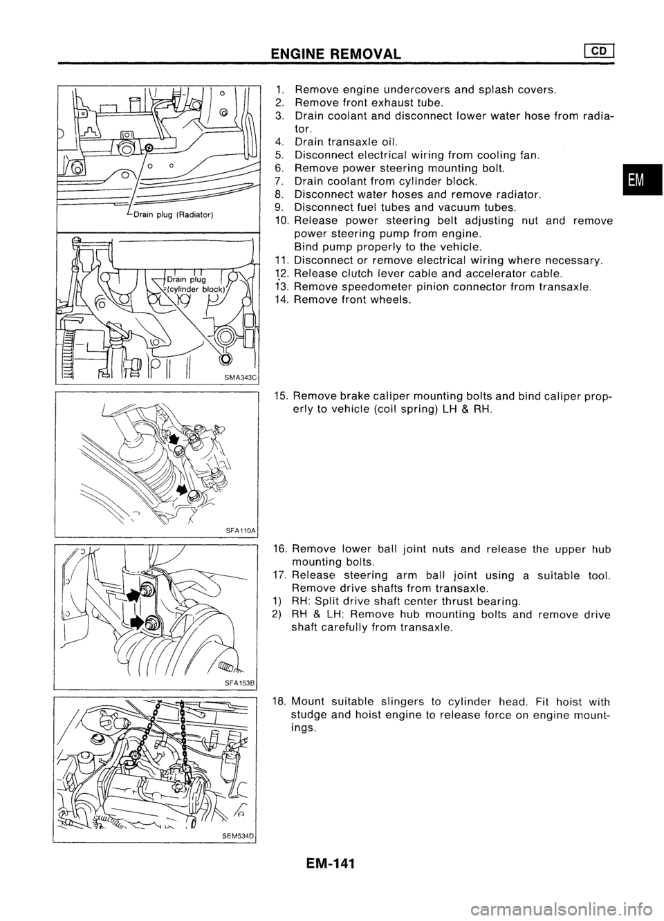
Drainplug(Radiator)
SFA110A
SFA 1538
SEM534D ENGINE
REMOVAL
1. Remove engineundercovers andsplash covers.
2. Remove frontexhaust tube.
3. Drain coolant anddisconnect lowerwater hosefromradia-
tor.
4. Drain transaxle oil.
5. Disconnect electricalwiringfromcooling fan.
6. Remove powersteering mounting bolt. •
7. Drain coolant fromcylinder block.
8. Disconnect waterhoses andremove radiator.
9. Disconnect fueltubes andvacuum tubes.
10. Release powersteering beltadjusting nutand remove
power steering pumpfromengine.
Bind pump properly tothe vehicle.
11. Disconnect orremove electrical wiringwhere necessary.
12. Release clutchlevercable andaccelerator cable.
13. Remove speedometer pinionconnector fromtransaxle.
14. Remove frontwheels.
15. Remove brakecaliper mounting boltsandbind caliper prop-
erly tovehicle (coilspring) LH
&
RH.
16. Remove lowerballjoint nutsandrelease theupper hub
mounting bolts.
17. Release steering armballjoint using asuitable tool.
Remove driveshafts fromtransaxle.
1) RH: Split drive shaftcenter thrustbearing.
2) RH
&
LH: Remove hubmounting boltsandremove drive
shaft carefully fromtransaxle.
18. Mount suitable slingers tocylinder head.Fithoist with
studge andhoist engine torelease forceonengine mount-
ings.
EM-141
Page 1371 of 1701
HOWTOREAD WIRING DIAGRAMS
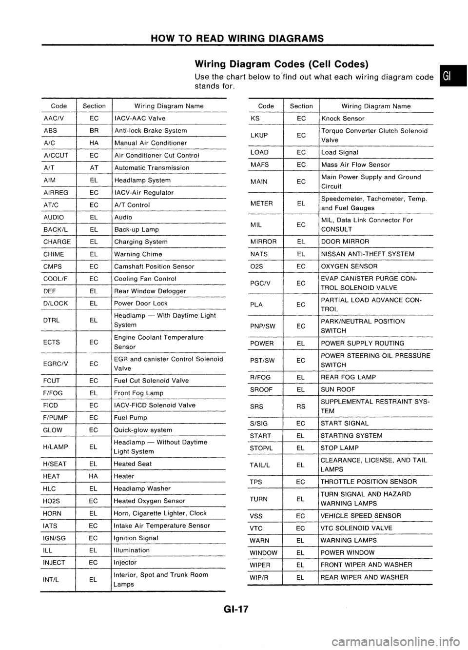
Wiring Diagram Codes(CellCodes)
Use thechart below to'find outwhat each wiring diagram code•
stands for,
Code Section WiringDiagram Name
AACIV ECIACV-AAC
Valve
ABS BR
Anti-lock BrakeSystem
A/C HAManualAirConditioner
A/CCUT ECAir
Conditioner CutControl
A/T ATAutomatic Transmission
AIM ELHeadlamp System
AIRREG ECIACV-Air Regulator
AT/C ECA/TControl
AUDIO ELAudio
BACK/L ELBack-up Lamp
CHARGE ELCharging System
CHIME ELWarning Chime
CMPS EC
Camshaft PositionSensor
COOllF ECCooling
FanControl
DEF ELRearWindow Defogger
D/LOCK ELPowerDoorLock
DTRL ELHeadlamp
-With Daytime Light
System
ECTS ECEngine
Coolant Temperature
Sensor
EGR andcanister ControlSolenoid
EGRCIV EC
Valve
FCUT ECFuel
CutSolenoid Valve
F/FOG ELFront
FogLamp
FICO ECIACV-FICD
SolenoidValve
F/PUMP ECFuel
Pump
GLOW ECQuick-glow
system
H/LAMP ELHeadlamp
-Without Daytime
Light System
H/SEAT ELHeated
Seat
HEAT HA
Heater
HLC ELHeadlamp
Washer
H02S ECHeated
Oxygen Sensor
HORN ELHorn,
Cigarette Lighter,Clock
IATS ECIntake
AirTemperature Sensor
IGN/SG ECIgnition
Signal
ILL ELIllumination
INJECT ECInjector
INT/L ELInterior,
SpotandTrunk Room
Lamps Code
Section WiringDiagram Name
KS ECKnock
Sensor
LKUP ECTorque
Converter ClutchSolenoid
Valve
LOAD ECLoadSignal
MAFS ECMass
AirFlow Sensor
MAIN ECMain
Power Supply andGround
Circuit
METER ELSpeedometer,
Tachometer,Temp.
and Fuel Gauges
MIL ECMIL,
Data LinkConnector For
CONSULT
MIRROR ELDOOR
MIRROR
NATS ELNISSAN
ANTI-THEFT SYSTEM
02S ECOXYGEN
SENSOR
EC EVAP
CANISTER PURGECON-
PGCIV TROLSOLENOID VALVE
PLA ECPARTIAL
LOADADVANCE CON-
TROL
EC PARK/NEUTRAL
POSITION
PNP/SW SWITCH
POWER ELPOWER
SUPPLY ROUTING
POWER STEERING OILPRESSURE
PST/SW EC
SWITCH
R/FOG ELREAR
FOGLAMP
SROOF ELSUN
ROOF
SUPPLEMENTAL RESTRAINTSYS-
SRS RS
TEM
S/SIG ECST
ART SIGNAL
START ELSTARTING
SYSTEM
STOP/L ELSTOP
LAMP
TAllIL ELCLEARANCE,
LICENSE,ANDTAIL
LAMPS
TPS ECTHROTTLE
POSITIONSENSOR
TURN SIGNAL ANDHAZARD
TURN EL
WARNING LAMPS
VSS ECVEHICLE
SPEEDSENSOR
VTC ECVTC
SOLENOID VALVE
WARN ELWARNING
LAMPS
WINDOW ELPOWER
WINDOW
WIPER ELFRONT
WIPERANDWASHER
WIP/R ELREAR
WIPER ANDWASHER
GI-17
Page 1399 of 1701
SAEJ1930 TERMINOLOGY LIST
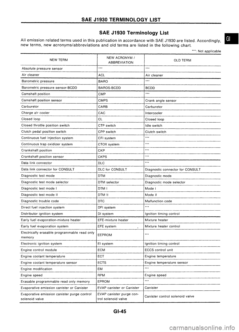
SAE J1930 Terminology List
All emission relatedtermsusedinthis publication inaccordance withSAE J1930 arelisted. Accordingly,
new terms, newacronyms/abbreviations andoldterms arelisted inthe following chart.
"':Not applicable
NEW TERM NEW
ACRONYM /
ABBREVIATION OLD
TERM
Absolute pressure sensor
'" '"
Air cleaner
ACLAircleaner
Barometric pressure
BARO
."
Barometric pressuresensor-BCDD
BAROS-BCDD BCDD
Camshaft position
CMP
'"
Camshaft positionsensor
CMPS Crankanglesensor
Carburetor CARBCarburetor
Charge aircooler
CACIntercooler
Closed loop
CLClosedloop
Closed throttle position switch
CTPswitch
Idleswitch
Clutch pedalposition switch
CPPswitch Clutchswitch
Continuous fuelinjection system
CFIsystem
'"
Continuous trapoxidizer system
CTOXsystem
...
Crankshaft position
CKP
'"
Crankshaft positionsensor
CKPS
~.**
Data linkconnector
DLC
,
..
Data linkconnector forCONSULT
DLCforCONSULT DiagnosticconnectorforCONSULT
Diagnostic testmode
DTMDiagnosticmode
Diagnostic testmode selector
DTMselector Diagnosticmodeselector
Diagnostic testmode I
DTMI ModeI
Diagnostic testmode II
DTMII ModeII
Diagnostic troublecode
DTC Malfunctioncode
Direct fuelinjection system
DFIsystem
..
,
Distributor ignitionsystem DIsystem Ignitiontimingcontrol
Early fuelevaporation-mixture heater
EFE-mixtureheater Mixture
heater
Early fuelevaporation system
EFEsystem
.
Mixture
heatercontrol
Electrically erasableprogrammable readonly
EEPROM
'"
memory
Electronic ignitionsystem EIsystem Ignitiontimingcontrol
Engine control module ECMECCScontrol unit
Engine coolant temperature ECTEngine
temperature
Engine coolant temperature sensor ECTS Engine
temperature sensor
Engine modification EM
'"
Engine speed RPM
Enginespeed
Erasable programmable readonlymemory EPROM
'"
Evaporative emissioncanisterorCanister EVAP
canister orCanister Canister
Evaporative emissioncanisterpurgecontrol EVAP
canister purgecon-
Canister controlsolenoid valve
solenoid valve trol
solenoid valve
GI-45
•
Page 1402 of 1701
SAEJ1930 TERMINOLOGY LIST
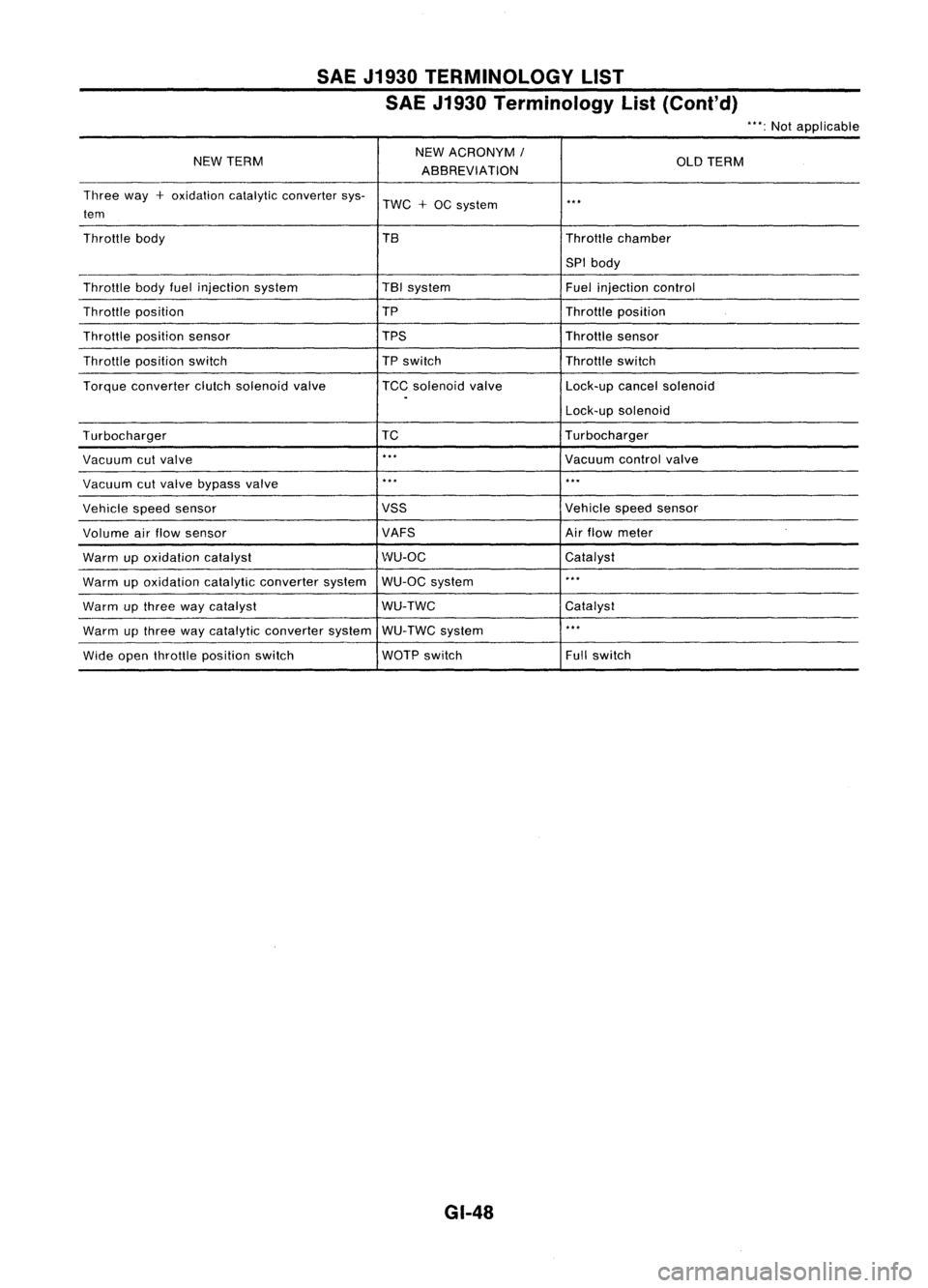
SAE J1930 Terminology List(Cont'd)
"':Not applicable
NEW TERM NEW
ACRONYM
I
OLDTERM
ABBREVIATION
Three way
+
oxidation catalyticconverter sys-
TWC
+
OC system
..
,
tem
Throttle body TBThrottlechamber
SPI body
Throttle bodyfuelinjection system TBI
system
Fuelinjection control
Throttle position TP
Throttleposition
Throttle position sensor TPSThrottlesensor
Throttle position switch
TP
switch Throttleswitch
Torque converter clutchsolenoid valve TCCsolenoid valve Lock-upcancelsolenoid
.
Lock-upsolenoid
Turbocharger TC
Turbocharger
Vacuum cutvalve
..
,
Vacuumcontrolvalve
Vacuum cutvalve bypass valve
..
,
...
Vehicle speedsensor VSS
Vehiclespeedsensor
Volume airflow sensor VAFSAir
flow meter
Warm upoxidation catalyst WU-OC
Catalyst
Warm upoxidation catalyticconverter systemWU-OC
system
..
,
Warm upthree waycatalyst WU-TWC
Catalyst
Warm upthree waycatalytic converter systemWU-TWC system
..
,
Wide open throttle position switch WOTP
switch Fullswitch
GI-48
Page 1403 of 1701
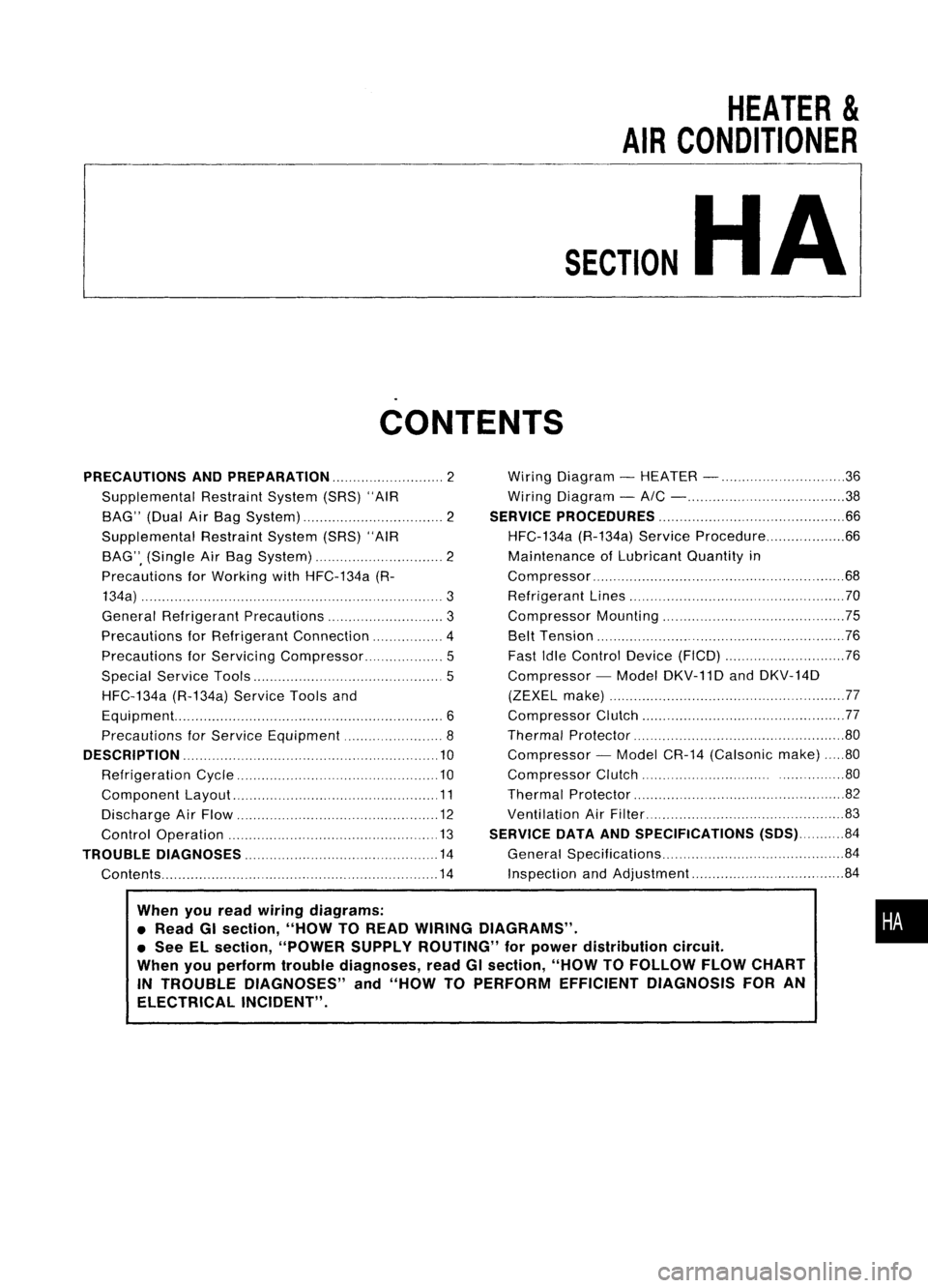
HEATER
&
AIR CONDITIONER
SECTION
HA
CONTENTS
When youread wiring diagrams:
• Read GIsection, "HOWTOREAD WIRING DIAGRAMS" .
• See ELsection, "POWER SUPPLYROUTING" forpower distribution circuit.
When youperform troublediagnoses, readGIsection, "HOWTOFOLLOW FLOWCHART
IN TROUBLE DIAGNOSES" and"HOW TOPERFORM EFFICIENT DIAGNOSIS FORAN
ELECTRICAL INCIDENT".
PRECAUTIONS
ANDPREPARATION 2
Supplemental RestraintSystem(SRS)"AIR
BAG" (DualAirBag System) 2
Supplemental RestraintSystem(SRS)"AIR
BAG", (Single AirBag System) 2
Precautions forWorking withHFC-134a (R-
134a) 3
General Refrigerant Precautions 3
Precautions forRefrigerant Connection 4
Precautions forServici ngCompressor. ..5
Special Service Tools 5
HFC-134a (R-134a)ServiceToolsand
Equipment. 6
Precautions forService Equipment 8
DESCRIPTION 10
Refrigeration Cycle .10
Component Layout 11
Discharge AirFlow 12
Control Operation 13
TROUBLE DIAGNOSES 14
Contents 14Wiring
Diagram -HEATER - 36
Wiring Diagram -
AIC - 38
SERVICE PROCEDURES 66
HFC-134a (R-134a)ServiceProcedure 66
Maintenance ofLubricant Quantityin
Compressor 68
Refrigerant Lines 70
Compressor Mounting 75
Belt Tension 76
Fast IdleControl Device(FICO) 76
Compressor -Model DKV-11D andDKV-14D
(ZEXEL make) 77
Compressor Clutch 77
Thermal Protector 80
Compressor -Model CR-14 (Calsonic make)80
Compressor Clutch ..80
Thermal Protector 82
Ventilation AirFilter 83
SERVICE DATAANDSPECIFICATIONS (SDS)84
General Specifications 84
Inspection andAdjustment 84
•
Page 1407 of 1701
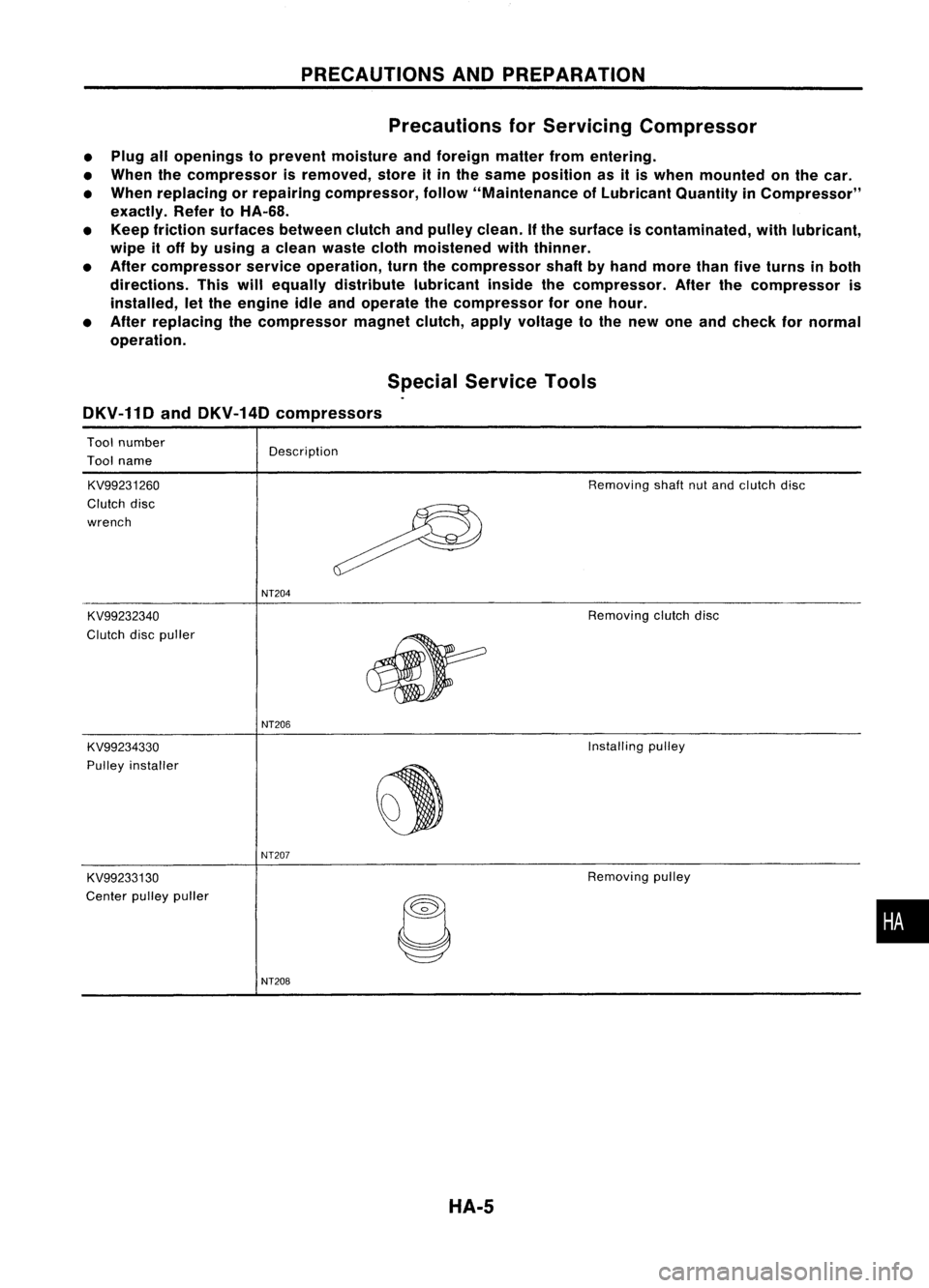
PRECAUTIONSANDPREPARATION
Precautions forServicing Compressor
• Plug allopenings toprevent moisture andforeign matterfromentering.
• When thecompressor isremoved, storeitin the same position asitis when mounted onthe car.
• When replacing orrepairing compressor, follow"Maintenance ofLubricant QuantityinCompressor"
exactly. RefertoHA-68.
• Keep friction surfaces betweenclutchandpulley clean.
If
the surface iscontaminated, withlubricant,
wipe itoff byusing aclean waste clothmoistened withthinner.
• After compressor serviceoperation, turnthecompressor shaftbyhand more thanfiveturns inboth
directions. Thiswillequally distribute lubricantinsidethecompressor. Afterthecompressor is
installed, letthe engine idleandoperate thecompressor forone hour.
• After replacing thecompressor magnetclutch,applyvoltage tothe new oneandcheck fornormal
operation.
SpecialService Tools
DKV-11D andDKV-14D compressors
Tool number
Tool name
KV99231260
Clutch disc
wrench
KV99232340
Clutch discpuller Description
NT204
Removing
shaftnutand clutch disc
Removing clutchdisc
NT206
KV99234330
Installing
pulley
PUlley installer
~
NT207
KV99233130
Removing
pulley
Center pulleypuller
C
•
NT208
HA-5
Page 1408 of 1701
PRECAUTIONSANDPREPARATION
Special Service Tools(Cont'd)
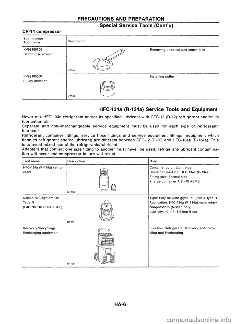
CR-14 compressor
Tool number
Tool name
KV99106700
Clutch discwrench
KV991 06800
Pulley installer Description
NT351
NT352
Removing
shaftnutand clutch disc
Installing pulley
HFC-134a (R-134a)ServiceToolsandEquipment
Never mixHFC-134a refrigerant and/oritsspecified lubricantwithCFC-12 (R-12)refrigerant and/orits
lubrication oil.
Separate andnon-interchangeable serviceequipment mustbeused foreach typeofrefrigerant/
lubricant.
Refrigerant containerfittings,servicehosefittings andservice equipment fittings(equipment which
handles refrigerant and/orlubricant) aredifferent between CFC-12(R-12)andHFC-134a (R-134a).This
is to avoid mixed useofthe refrigerants/lubricant.
Adapters thatconvert onesize fitting toanother mustnever beused: refrigerant/lubricant contamina-
tion willoccur andcompressor failurewillresult.
Tool name
Description Note
HFC-134a (R-134a)refrig-
~~
Container
color:Lightblue
erant Containermarking:HFC-134a (R-134a)
Fitting size:Thread size
• large contai ner1/2"-16 ACME
NT196
Nissan A/CSystem Oil Type:Polyalkyline glycoloil(pAG), typeR
Type R
~
Application:
HFC-134a(R-134a)vanerotary
(Part No.:KLHOO-PAGRO)
compressors(Nissanonly)
Lubricity: 40me (1.4 Imp
fI
oz)
NT197
Recovery/Recycling/
~
Function:
Refrigerant RecoveryandRecy-
Recharging equipment
":'s
Q"'~
cling
andRecharging
==
•
~ t:J
~
II
NT195
HA-6
Page 1412 of 1701
DESCRIPTION
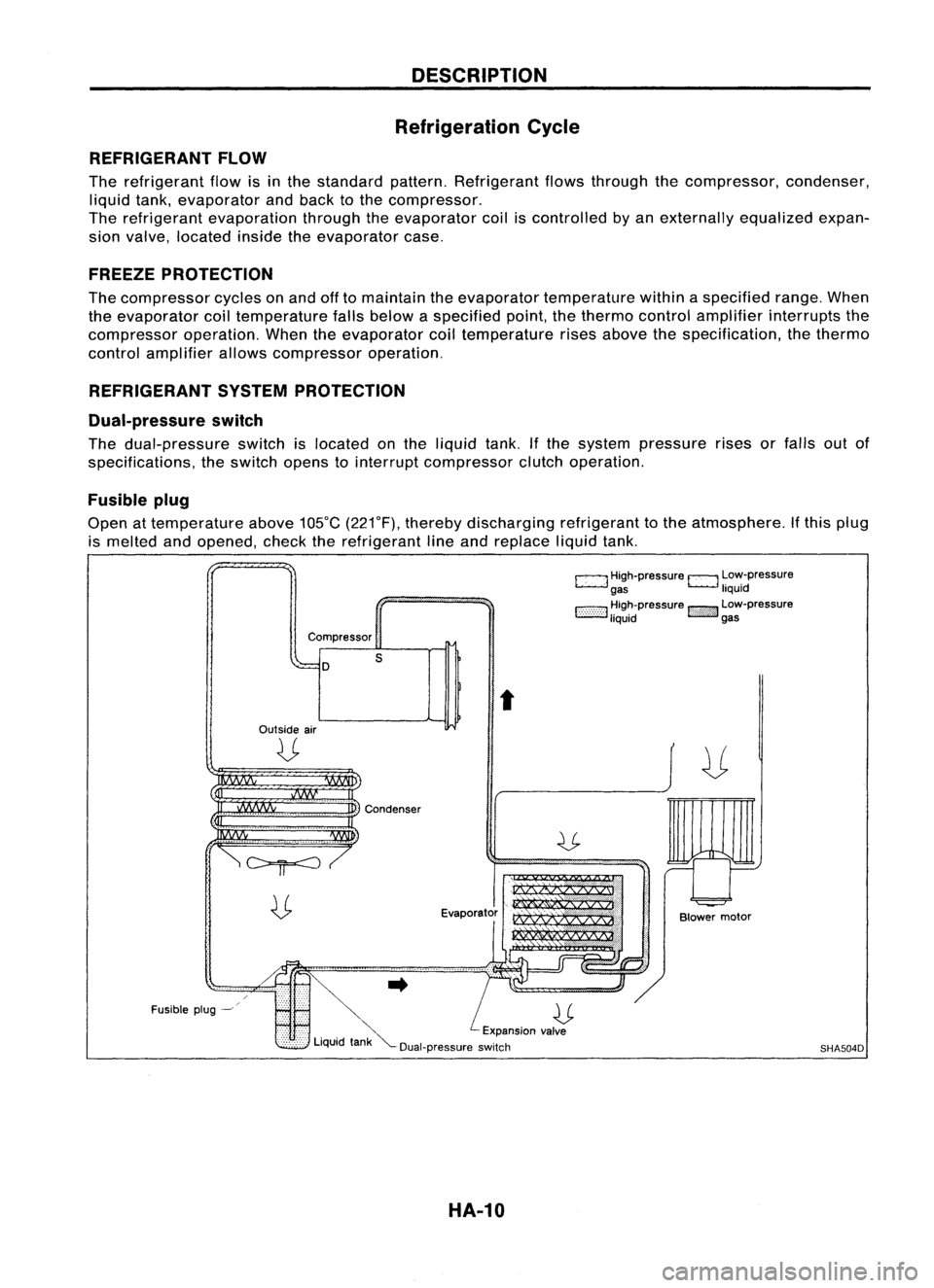
Refrigeration Cycle
REFRIGERANT FLOW
The refrigerant flowisinthe standard pattern.Refrigerant flowsthrough thecompressor, condenser,
liquid tank,evaporator andback tothe compressor.
The refrigerant evaporation throughtheevaporator coiliscontrolled byan externally equalizedexpan-
sion valve, located insidetheevaporator case.
FREEZE PROTECTION
The compressor cyclesonand offtomaintain theevaporator temperature withinaspecified range.When
the evaporator coiltemperature fallsbelow aspecified point,thethermo controlamplifier interrupts the
compressor operation.Whentheevaporator coiltemperature risesabove thespecification, thethermo
control amplifier allowscompressor operation.
REFRIGERANT SYSTEMPROTECTION
Dual-pressure switch
The dual-pressure switchislocated onthe liquid tank.Ifthe system pressure risesorfalls outof
specifications, theswitch openstointerrupt compressor clutchoperation.
Fusible plug
Open attemperature above105°C(221°F), thereby discharging refrigeranttothe atmosphere. Ifthis plug
is melted andopened, checktherefrigerant lineand replace liquidtank.
c:::::.J
High-pressure
EJ
Low-pressure
gas liquid
1:-:-:-:-::-:-::-:-:1
~~~~pressure
!::i'i'i':}':J
~~:-pressure
Compressor
D
Outside air
U
s
t
Fusible plug-~
~..
U
'" Expansionvalve
Liquid tank"'--Dual-pressure switch
HA-10
Blower
motor
SHA504D