Page 1575 of 1701

MAJOROVERHAUL
I
RS5F32A
I
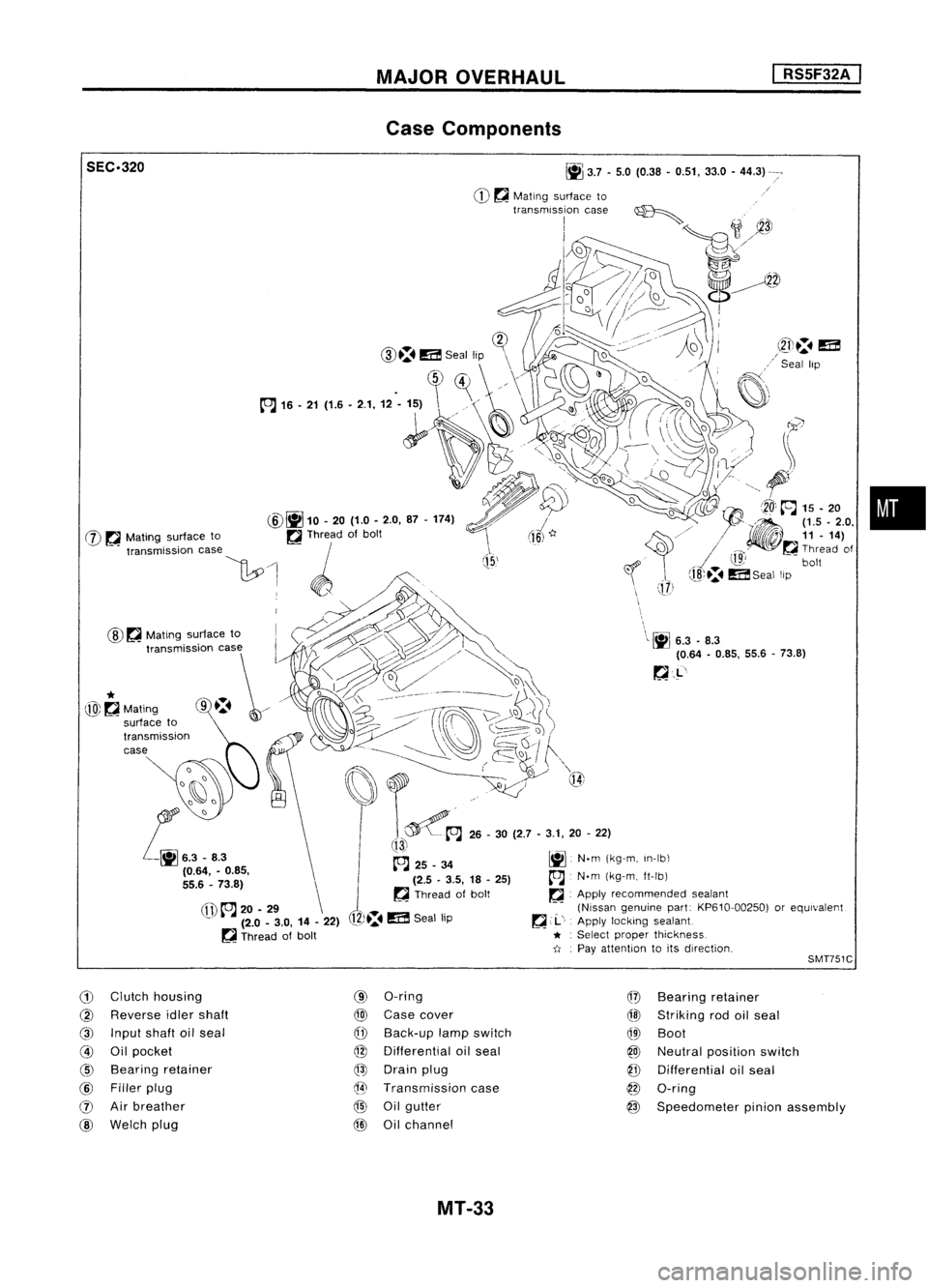
Case Components
•
\
\L~
6.3.8.3
(0.64 -0.85, 55.6-73.8)
~.L'
J
(15,'
~
3.7•5.0 (0.38 •0.51, 33.0-44.3)
CD ~
Mating surface to
transmission case~
I
;1
~3J
1J2»~
o//~
d~~~
!-~~
i~=1D.
(]?
CID.:.
m
Seal lip \
\
.
~)~
//\
1~
~'
(fl)
to.J
20-29 \
- (2.0-3.0, 14-22)
~ Thread ofbolt
@
~
Mating surface to
SEC.320
@~
10.20 (1.0-2.0, 87-174)
W ~
Mating surface to ~Thread ofbolt
"""mi"ioo '""
\1:.0
1 ~ /',
. WO,,~., .,.~
~~~> '\
t,,~~~~
o
I:::t:\ ~___-- __~
j)\~
~i)~/
(ro\~\~)
. ------ ~~,/ ~Q~
I
f""\
~~~ ..~ Q{
t~A
26-30 (2.7 -3.1, 20-22)
!13i
~ 25_34 ~N.m(kg-m, In-Ib\
(2.5 -3.5, 18-25)
A
N.m(kg-m, ft-Ib)
~ Thread ofbolt ~.Apply recommended sealant
(Nissan genuine part:KP610-00250) orequivalent
12)~.
m
Seal lip ~
,.1..',
Apply locking sealant
* :
Select proper thickness.
-tI .
Pay attention toits direction,
*
@~Mating
SMT751C
G)
Clutch housing
@
Reverse idlershaft
@
Input shaftoilseal
@
Oilpocket
@
Bearing retainer
@
Filler plug
(J)
Airbreather
@
Welch plug
(9)
O-ring
@
Case cover
CfD
Back-up lampswitch
@
Differential oilseal
@
Drain plug
@
Transmission case
@
Oilgutter
@
Oilchannel
@
Bearing retainer
@l
Striking rodoilseal
QID
Boot
@
Neutral position switch
@
Differential oilseal
@
O-ring
@
Speedometer pinionassembly
MT-33
Page 1579 of 1701
DISASSEMBlY
I
RS5F32A
I
SMT6708
SMT6718
SMT64BAA
6.
Remove controlbracket with1st
&
2nd shift fork.
7. Remove gearcomponents fromclutch housing.
a. Remove inputshaftfrontbearing retainer securing bolts.
b. Remove inputshaftwithbearing retainer, mainshaft assem-
bly and reverse idlergear.
• Always withdraw mainshaft straightout.Failure todo so
can damage resinoilchannel onclutch housing side.
• Do not draw outreverse idlershaft fromclutch housing
because thesefittings willbeloose.
When removing inputshaft, becareful nottoscratch oilseal
lip with shaft spline.
c. Remove finaldrive assembly.
8. Remove oilpocket, shiftcheck ball,shiftcheck spring and
check ballplug.
MT-37
•
Page 1580 of 1701
DISASSEMBLV
I
RS5F32A
I
SMT599AA SMT583
9.
Drive retaining pinout ofstriking lever,thenremove strik-
ing rod, striking leverandstriking interlock.
• Select aposition whereretaining pindoes notinterfere with
clutch housing whenremoving retainingpin.
• Becareful nottodamage oilseal lip,when removing strik-
ing rod. Ifnecessary, tapeedges ofstriking rod.
10. Remove reversecheckplug,thendetach reverse check
spring andcheck balls.
• Ifthe smaller balldoes notcome out,remove ittogether
with check sleeve assembly.
Check sleeve
assembly SMT585
11.
Remove checksleeve assembly.
MT-38
Page 1592 of 1701
Strikinglever
Reverse brakeearn REPAIR
FORCOMPONENT PARTS
Shift Control Components (Cont'd)
SMT099C I
RS5F32A
I
ADJUSTMENT OFINPUT SHAFT BRAKING MECHANISM
1. Install striking lever
&
rod, striking interlock assembly and
control bracket onclutch housing exactly.
• When installing controlbracket onclutch housing, assure
protrusion beneathbracketiscorrectly seated.
SMT774B
Height
gauge
2.
Measure maximum height"H"while shifting fromneutral to
reverse position.
Maximum height
"H":
67.16 -67.64
mm
(2.6441 .2.6630
in)
Control bracket
fitting surface 1
st
&
2nd shifter
~
Reverse brakecarn
SMT728B
MT-SO
Page 1596 of 1701

ADJUSTMENT
I
RS5F32A
I
SMT646-A
SMT454-B Differential
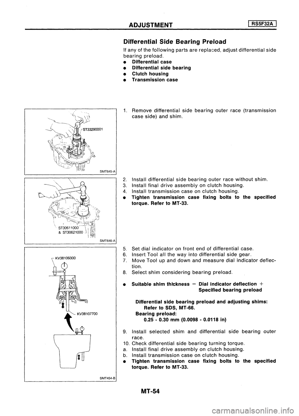
SideBearing Preload
If any ofthe following partsarereplaced, adjustdifferential side
bearing preload.
• Differential case
• Differential sidebearing
• Clutch housing
• Transmission case
1. Remove differential sidebearing outerrace(transmission
case side) andshim.
2. Install differential sidebearing outerracewithout shim.
3. Install finaldrive assembly onclutch housing.
4. Install transmission caseonclutch housing.
• Tighten transmission casefixing boltstothe specified
torque. RefertoMT -33.
5. Set dial indicator onfront endofdifferential case.
6. Insert Toolallthe way intodifferential sidegear.
7. Move Toolupand down andmeasure dialindicator deflec-
tion.
8. Select shimconsidering bearingpreload.
• Suitable shimthickness
=
Dial indicator deflection +
Specified bearingpreload
Differential sidebearing preload andadjusting shims:
Refer toSDS, MT-66.
Bearing preload:
0.25 -0.30 mm(0.0098 -0.0118 in)
9. Install selected shimanddifferential sidebearing outer
race.
10. Check differential sidebearing turningtorque.
a. Install finaldrive assembly onclutch housing.
b. Install transmission caseonclutch housing.
• Tighten transmission casefixing boltstothe specified
torque. RefertoMT-33.
MT-54
Page 1598 of 1701

ASSEMBLY
I
RS5F32A ,
J
Reverse checkplug
~ Reverse checkspring
V
Check ball(Large)
"-- Check ball(Small)
b~6
,
~
l ~---- -'.
SMT584
SMT688
SMT648AA SMT671B
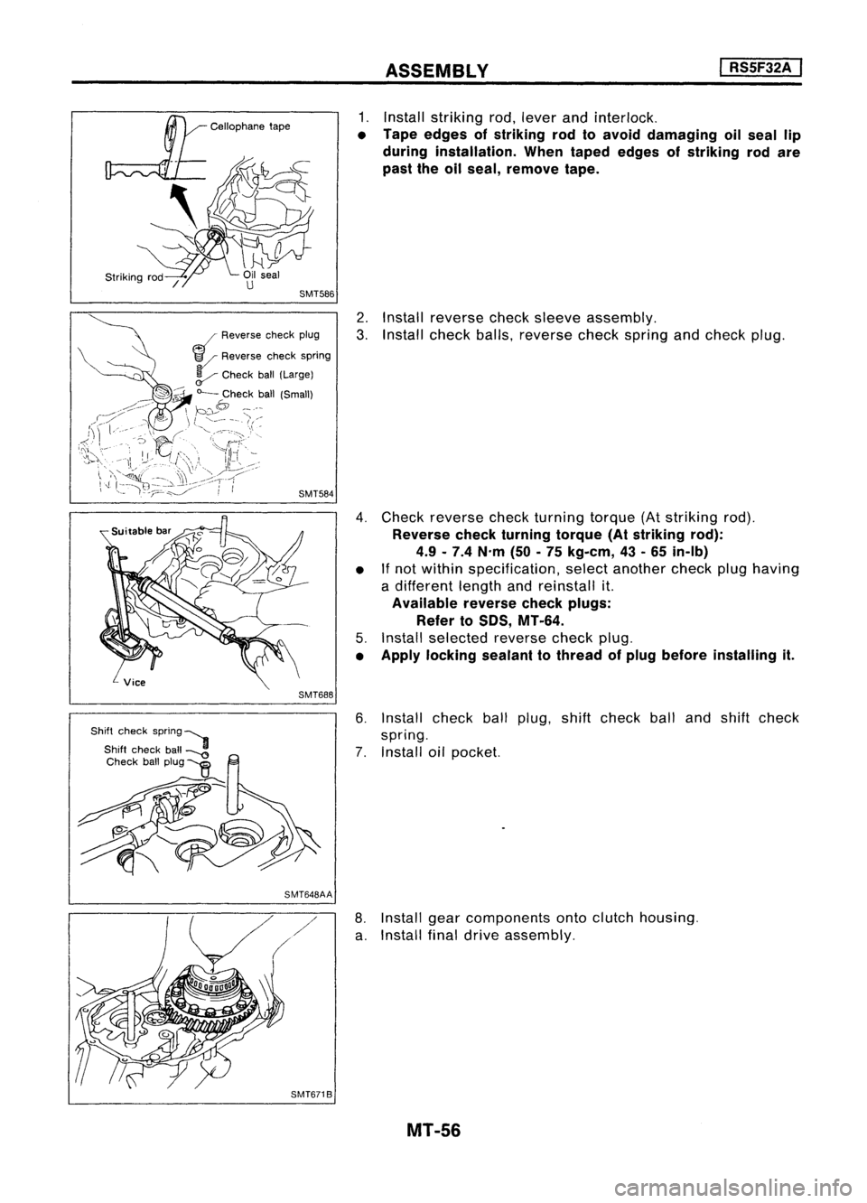
1.
Install striking rod,lever andinterlock.
• Tape edges ofstriking rodtoavoid damaging oilseal lip
during installation. Whentaped edges ofstriking rodare
past theoilseal, remove tape.
2. Install reverse checksleeve assembly.
3. Install check balls,reverse checkspring andcheck plug.
4. Check reverse checkturning torque(Atstriking rod).
Reverse checkturning torque(Atstriking rod):
4.9 -7.4 N'm (50-75 kg-em, 43-65 in-Ib)
• If
not within specification, selectanother checkplughaving
a different lengthandreinstall it.
Available reversecheckplugs:
Refer to
50S,
MT-64.
5. Install selected reversecheckplug.
• Apply locking sealanttothread ofplug before installing it.
6. Install checkballplug, shiftcheck ballandshift check
spring.
7. Install oilpocket.
8. Install gearcomponents ontoclutch housing.
a. Install finaldrive assembly.
MT-56
Page 1599 of 1701
ASSEMBLY
I
RSSF32A
I
SMT666
SMT774B
b.
Install inputshaft assembly withbearing retainer, mainshaft
assembly andreverse idlergear.
• Becareful nottodamage oilseal lipwith splines ofinput
shaft.
• Becareful nottodamage oilchannel wheninserting main-
shaft intoclutch housing.
c. Install inputshaftfrontbearing retainer.
9. Apply grease toshifter caps,theninstall itto control
bracket. Installcontrol bracket with1st
&
2nd shift fork.
• When installing controlbracket onclutch housing, ensure
bracket iscorrectly seated.
10. Install 3rd
&
4th and 5thshift forks.
•
SMT596
11.
Insert forkshaft.
• Apply multi-purpose greasetosupport springbefore install-
ing.
12. Install reverse idlerspacer.
MT-57
Page 1600 of 1701
ASSEMBLY
I
RS5F32A
I
SMT666B
13.
Apply recommended sealanttomating surface ofclutch
housing.
14. Install transmission caseonclutch housing.
Snap ring
SMT665B
SMT775B
15.
Install mainshaft frontbearing snapring.
16. -Check mainshaft bearingendplay.
Mainshaft bearingendplay:
o -
0.1 mm (0-0.004 in)
• Make surethatbearing isproperly seated.
If
not, tapmain
shaft endwith arubber hammer.
• Ifnot within specification, selectanother casecover having
a different thickness.
Available casecovers:
Refer to50S, MT-64.
MT-58