1995 NISSAN ALMERA N15 width
[x] Cancel search: widthPage 356 of 1701
SERVICEDATAANDSPECIFICATIONS (SOS)
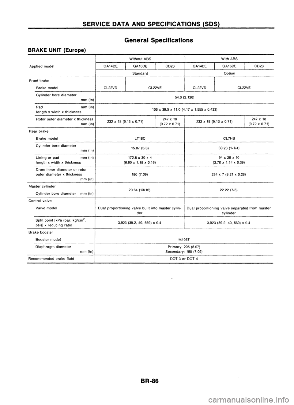
General Specifications
BRAKE UNIT(Europe)
WithoutABS WithABS
Applied model GA14DE
GA16DE
I
CD20
GA14DE GA16DE
I
CD20
Standard Option
Front brake
Brake model CL22VDCL22VECL22VD CL22VE
Cylinder borediameter
54.0(2.126)
mm (in)
Pad mm(in)
106x39.5 x11.0 (4.17 x1.555 x0.433)
length xwidth xthickness
Rotor outerdiameter xthickness
232x18 (9.13 x0.71)
I
247
x18
232x18 (9.13 x0.71)
I
247
x18
mm (in) (972x0.71) (9.72x0.71)
Rear brake
Brake model
LT18C CL7HB
Cylinder borediameter
15.87(5/8) 30.23(1-1/4)
mm (in)
Lining orpad mm
(in)
172.8x30 x4 94x29 x10
length xwidth xthickness (6.80x1.18 x0.16) (3.70x1.14 x0.39)
Drum innerdiameter orrotor
outer diameter xthickness 180(7.09) 234x7 (9.21 x0.28)
mm (in)
Master cylinder
20.64(13/16) 22.22(7/8)
Cylinder borediameter
mm(in)
Control valve
Valve model Dualproportioning valvebuiltintomaster cylin-
Dualproportioning valveseparated frommaster
der cylinder
Split point [kPa(bar. kg/cm
2•
3.923(39.2. 40.569) x0.4
3.923(39.2. 40.569) x0.4
psi)] xreducing ratio
Brake booster
Booster model
M195T
Diaphragm diameter
Primary:205(8.07)
mm (in)
Secondary:180(7.09)
Recommended brakefluid
DOT3or DOT 4
BR-86
Page 357 of 1701
SERVICEDATAANDSPECIFICATIONS (SDS)
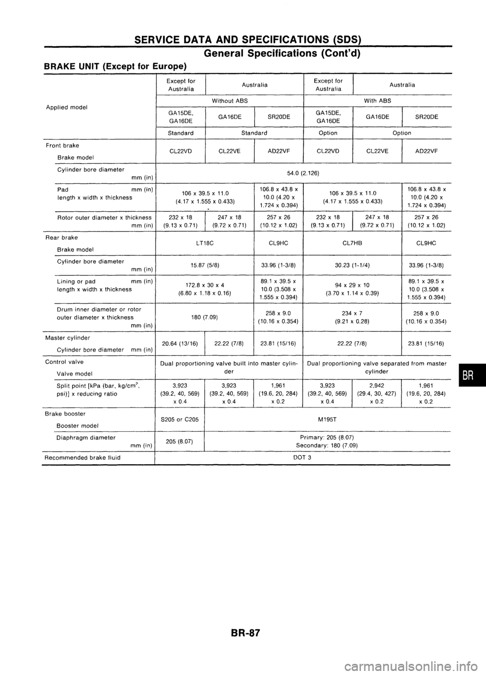
General Specifications (Cont'd)
BRAKE UNIT(Except forEurope)
Except for
Australia Except
for
Australia
Australia Australia
Without ABS With
ABS
Applied model
GA15DE.GA16DESR20DEGA15DE.
GA16DESR20DE
GA16DE GA16DE
Standard Standard Option
Option
Front brake
CL22VDCL22VE AD22VF
CL22VD CL22VEAD22VF
Brake model
Cylinder borediameter
54.0(2.126)
mm (in)
Pad mm
(in)
106x39.5 x11.0 106.8
x43.8 x
106x39.5x11.0 106.8
x43.8 x
length xwidth xthickness
(4.17x1.555 x0.433) 10.0
(4.20 x
(417x1.555 x0.433) 10.0
(4.20 x
.
1.724
x0.394)
1.724x0.394)
Rotor outerdiameter xthickness 232
x18 247x18 257x26 232x18 247
x18
257x26
mm (in) (9.13x0.71) (9.72
x0.71) (10.12x1.02) (9.13x0.71) (9.72x0.71) (10.12x1.02)
Rear brake
LT18CCL9HC CL7HB
CL9HC
Brake model
Cylinder borediameter
15.87(5/8) 33.96(1-3/8) 30.23(1-1/4) 33.96(1-3/8)
mm (in)
Lining orpad mm
(in)
172.8x30 x4 89.1
x39.5 x
94x29 x10 89.1
x39.5 x
length xwidth xthickness
(6.80x1.18 x0.16) 10.0
(3.508 x
(370x1.14 x0.39) 10.0
(3.508 x
1.555 x0.394)
1555x0.394)
Drum innerdiameter orrotor
258x9.0 234x7
258x9.0
outer diameter xthickness 180
(7.09)
(10.16x0.354) (9.21x0.28)
(10.16x0.354)
mm (in)
Master cylinder
20.64(13/16) 22.22
(7/8) 23.81(15/16) 22.22(7/8) 23.81(15/16)
Cylinder borediameter mm
(in)
Control valve
Dualproportioning valvebuiltintomaster cylin- Dualproportioning valveseparated frommaster
Valve model der
cylinder
Split point [kPa(bar.
kg/cm'.
3.923
3.923 1.9613.923 2.942
1.961
psi)] xreducing ratio (39.2.40.569) (39.2.40.569) (19.6.
20.284)
(39.2.40.569) (29.4.30.427) (19.6.20.284)
x 0.4 x0.4 x
0.2
x0.4 x
0.2
x0.2
Brake booster
S205orC205 M195T
Booster
model
Diaphragm diameter
205(8.07) Primary:
205(8.07)
mm (in) Secondary:180(7.09)
Recommended brakefluid DOT
3
BR-87
•
Page 744 of 1701
•
OPEN
LOOPCONTROL
The open loopsystem condition referstowhen theECM detects
any ofthe following conditions. Feedbackcontrolstopsinorder
to maintain stabilized fuelcombustion.
• Deceleration andacceleration
• High-load, high-speed operation
• Engine idling
• Malfunction ofoxygen sensor*1 orits circuit
• Insufficient activationofoxygen sensor*1 atlow engine
coolant temperature
• High-engine coolanttemperature
• After shifting from"N"to"D"
• During warm-up
• When starting theengine
ENGINE
ANDEMISSION BASICCONTROL SYSTEMDESCRIPTION
[ill
Multipart FuelInjection (MFI)System (Cant'd)
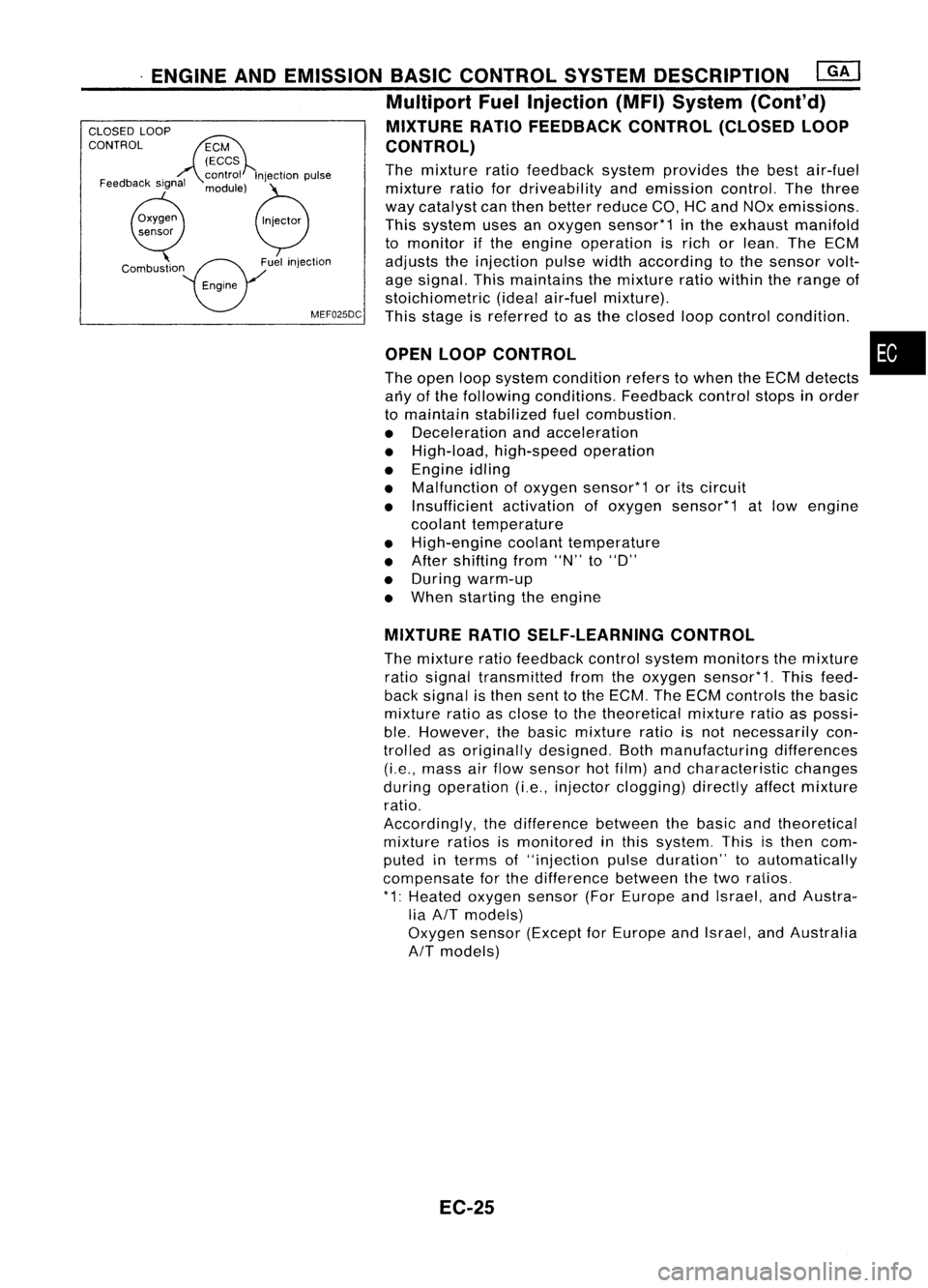
MIXTURE RATIOFEEDBACK CONTROL(CLOSEDLOOP
CONTROL)
The mixture ratiofeedback systemprovides thebest air-fuel
mixture ratiofordriveability andemission control.Thethree
way catalyst canthen better reduce CO,HCand NOx emissions.
This system usesanoxygen sensor*1 inthe exhaust manifold
to monitor ifthe engine operation isrich orlean. TheECM
adjusts theinjection pulsewidthaccording tothe sensor volt-
age signal. Thismaintains themixture ratiowithin therange of
stoichiometric (idealair-fuel mixture).
MEF025DC
Thisstage isreferred toas the closed loopcontrol condition .
Feedback
signal
CLOSED
LOOP
CONTROL
MIXTURERATIOSELF-LEARNING CONTROL
The mixture ratiofeedback controlsystem monitors themixture
ratio signal transmitted fromtheoxygen sensor*1. Thisfeed-
back signal isthen senttothe ECM. TheECM controls thebasic
mixture ratioasclose tothe theoretical mixtureratioaspossi-
ble. However, thebasic mixture ratioisnot necessarily con-
trolled asoriginally designed. Bothmanufacturing differences
(i.e., mass airflow sensor hotfilm) andcharacteristic changes
during operation (i.e.,injector clogging) directlyaffectmixture
ratio.
Accordingly, thedifference betweenthebasic andtheoretical
mixture ratiosismonitored inthis system. Thisisthen com-
puted interms of"injection pulseduration" toautomatically
compensate forthe difference betweenthetwo ratios.
* 1: Heated oxygen sensor(ForEurope andIsrael, andAustra-
lia AIT models)
Oxygen sensor(Except forEurope andIsrael, andAustralia
AIT
models)
EC-25
Page 745 of 1701
![NISSAN ALMERA N15 1995 Service Manual
Twotypes ofsystems areused.
ENGINE
ANDEMISSION BASICCONTROL SYSTEMDESCRIPTION
@K]
Multipart FuelInjection (MFI)System (Cont'd)
FUEL INJECTION TIMING
/ Injection pUlse
No.1 cylinder
---r:T _
NISSAN ALMERA N15 1995 Service Manual
Twotypes ofsystems areused.
ENGINE
ANDEMISSION BASICCONTROL SYSTEMDESCRIPTION
@K]
Multipart FuelInjection (MFI)System (Cont'd)
FUEL INJECTION TIMING
/ Injection pUlse
No.1 cylinder
---r:T _](/manual-img/5/57349/w960_57349-744.png)
Twotypes ofsystems areused.
ENGINE
ANDEMISSION BASICCONTROL SYSTEMDESCRIPTION
@K]
Multipart FuelInjection (MFI)System (Cont'd)
FUEL INJECTION TIMING
/ Injection pUlse
No.1 cylinder
---r:T _
No.2 cylinder
rL
No.3 cylinder
n.... _
No.4 cylinder
n....__
Sequential
multiportfuelinjection system
Fuel isinjected intoeach cylinder duringeachengine cycle
according tothe firing order. Thissystem isused when the
engine isrunning.
~ 1engine cycle
----j
Sequential multiportfuelinjection system
MEF522D
No. 1cylinder
jl
n
n-
No.2 cylinder
jl
n
n-
No. 3cylinder
.n
n
rL-
No.4 cylinder
j1~
n....
rL-
f---
1engine cycle
-l
Simultaneous multiportfuelinjection system
MEF523D Simultaneous
multiportfuelinjection system
Fuel isinjected simultaneously intoallfour cylinders twiceeach
engine cycle.Inother words, pulsesignals ofthe same width
are simultaneously transmittedfromtheECM.
The four injectors willthen receive thesignals twotimes for
each engine cycle.
This system isused when theengine isbeing started and/orif
the fail-safe system(CPU)isoperating.
FUEL SHUT-OFF
Fuel toeach cylinder iscut offduring deceleration oroperation
of the engine andthevehicle atexcessively highspeeds.
EC-26
Page 746 of 1701
ENGINEANDEMISSION BASICCONTROL SYSTEMDESCRIPTION
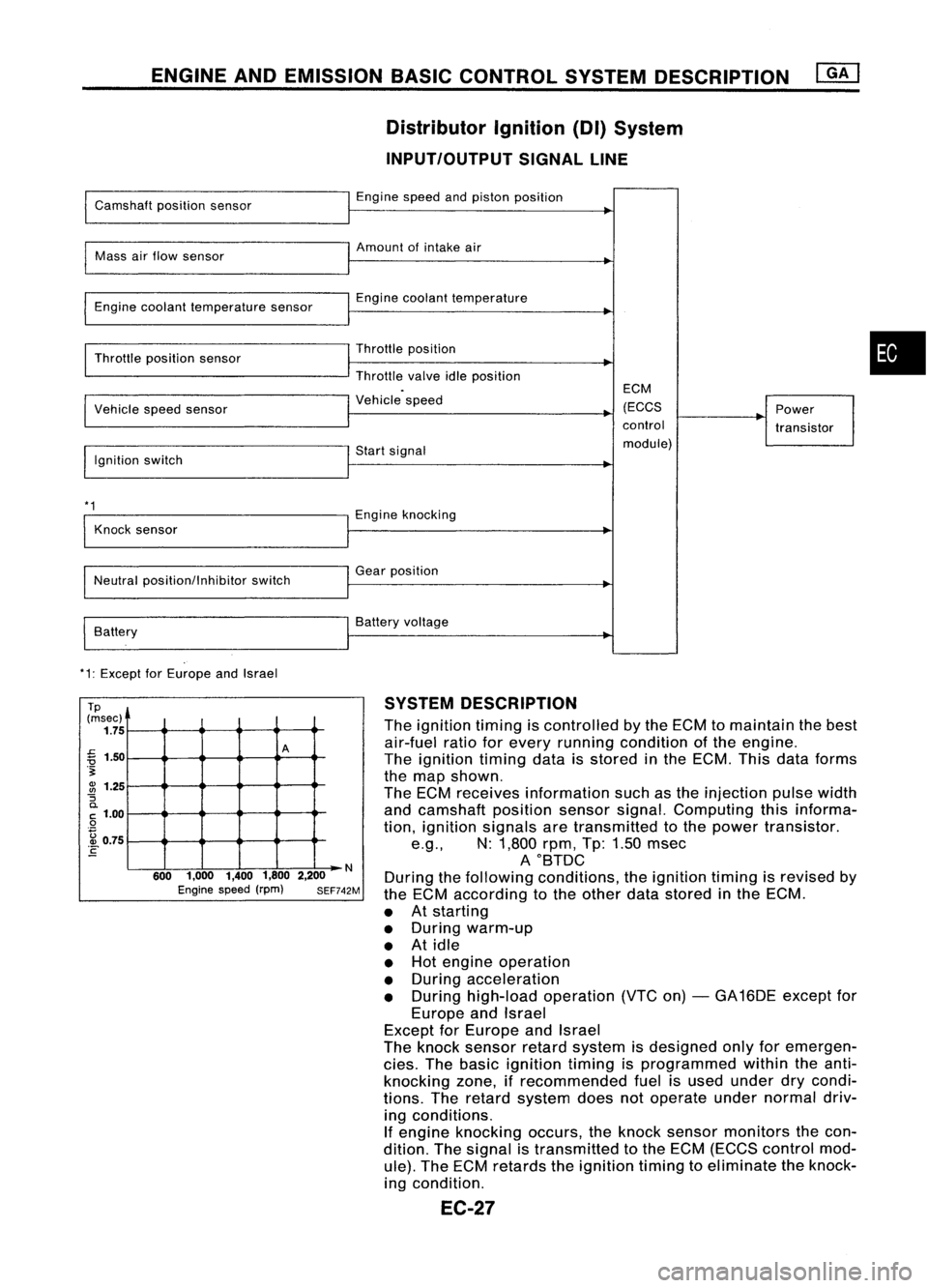
Distributor Ignition(DI)System
INPUT/OUTPUT SIGNALLINE
Camshaft positionsensor
Mass airflow sensor
Engine coolant temperature sensor
Throttle position sensor
Vehicle speedsensor
Ignition switch
*1
Knock sensor
Neutral position/Inhibitor switch
Battery
*1: Except forEurope andIsrael Engine
speedandpiston position
Amount ofintake air
Engine coolant temperature
Throttle position
Throttle valveidleposition
Vehicle speed
Start signal
Engine knocking
Gear position
Battery voltage ECM
(ECCS
control
module) Power
transistor
•
Tp
(msec)
1.75
~ 1.50
.~
~ 1.25
"S
0.
C
1.00
o
. ~ 0.75
E
A
N
600 1,000 1,4001,8002,200
Engine speed(rpm) SEF742M
SYSTEM
DESCRIPTION
The ignition timingiscontrolled bythe ECM tomaintain thebest
air-fuel ratioforevery running condition ofthe engine.
The ignition timingdataisstored inthe ECM. Thisdata forms
the map shown.
The ECM receives information suchasthe injection pulsewidth
and camshaft positionsensorsignal.Computing thisinforma-
tion, ignition signals aretransmitted tothe power transistor .
e.g., N:1,800 rpm,Tp:1.50 msec
AOBTDC
During thefollowing conditions, theignition timingisrevised by
the ECM according tothe other datastored inthe ECM.
• Atstarting
• During warm-up
• Atidle
• Hot engine operation
• During acceleration
• During high-load operation (VTCon)-GA 16DE except for
Europe andIsrael
Except forEurope andIsrael
The knock sensor retardsystem isdesigned onlyforemergen-
cies. Thebasic ignition timingisprogrammed withintheanti-
knocking zone,ifrecommended fuelisused under drycondi-
tions. Theretard system doesnotoperate undernormal driv-
ing conditions.
If engine knocking occurs,theknock sensor monitors thecon-
dition. Thesignal istransmitted tothe ECM (ECCS control mod-
ule). TheECM retards theignition timingtoeliminate theknock-
ing condition.
EC-27
Page 771 of 1701
![NISSAN ALMERA N15 1995 Service Manual ON-BOARDDIAGNOSTIC SYSTEMDESCRIPTION
CONSULT (Coni'd)
Monitored item
ECM
Main
[Unit] input
signals Description
Remarks
signals
LOAD SIGNAL •Indicates [ON/OFF] conditionfromthe
[ON/OFF] reardefo NISSAN ALMERA N15 1995 Service Manual ON-BOARDDIAGNOSTIC SYSTEMDESCRIPTION
CONSULT (Coni'd)
Monitored item
ECM
Main
[Unit] input
signals Description
Remarks
signals
LOAD SIGNAL •Indicates [ON/OFF] conditionfromthe
[ON/OFF] reardefo](/manual-img/5/57349/w960_57349-770.png)
ON-BOARDDIAGNOSTIC SYSTEMDESCRIPTION
CONSULT (Coni'd)
Monitored item
ECM
Main
[Unit] input
signals Description
Remarks
signals
LOAD SIGNAL •Indicates [ON/OFF] conditionfromthe
[ON/OFF] reardefogger signaland/or lighting
switch.
0 0
ON:
Rear defogger isoperating
and/or lighting switchison.
OFF: Rear defogger isnot operating
and lighting switchisnot on.
INJ PULSE [msec]
0
•
Indicates theactual fuelinjection
•When theengine isstopped, acertain
pulse widthcompensated byECM computedvalueisindicated.
according tothe input signals.
IGN TIMING [BTDC]
0
•
Indicates theignition timingcomputed
by ECM according tothe input sig-
nals.
IACV-AACIV
[%]
•Indicates theidle aircontrol valve
0
(AAC
valve) control valuecomputed
by ECM according tothe input sig-
nals.
A/F ALPHA
[%]
•Indicates themean valueofthe air-
•When theengine isstopped, acertain
0
fuel
ratio feedback correction factor valueisindicated.
per cycle. •This data alsoincludes thedata for
the air-fuel ratiolearning control.
AIR COND RLY
0
•
Indicates theairconditioner relay
[ON/OFF] controlcondition (determined byECM
according tothe input signal).
COOLING FAN*2
•Indicates thecontrol condition ofthe
[ON/OFF] or[LOW/
coolingfans(determined byECM
HI/OFF]
0
according
tothe input signal).
ON ...Operating
LOW ...Operates atlow speed
HI ...Operates athigh speed
OFF ...Stopped
FUEL PUMP RLY
0
•
Indicates thefuel pump relaycontrol
[ON/OFF] conditiondetermined byECM accord-
ing tothe input signals.
VALVE TIMSOL*1
•The control condition ofthe valve tim-
[ON/OFF] ingsolenoid valve(determined by
ECM according tothe input signal) is
indicated.
ON ...VTC operating
OFF ...VTC notoperating
EGRC SOLIV (EVAP
•Indicates thecontrol condition ofthe
canister purgecon-
EVAPcanister purgecontrol solenoid
trol solenoid valve valveorEGR valve
&
EVAP canister
or EGR
&
EVAP can- purgecontrol solenoid valve(deter-
ister purge control
0
mined
byECM according tothe input
solenoid valve) signal).
[ON/OFF] ON'"EVAP canister purgeoperation
cut-off OFF ...EVAP canister purgeoperation
not cut-off
VOLTAGE •Voltage measured bythe voltage
[V] probe.
PULSE •Pulse width, frequency orduty cycle •Only "#"isdisplayed ifitem is
[msec] or[Hz] or measuredbythe pulse probe. unable
tobe measured .
[%]
•
Figures with"#"s aretemporary
ones. Theyarethesame figures as
an actual pieceofdata which wasjust
previously measured.
*1: GA16DE exceptforEurope andIsrael
*2: GA16DE engineA/Tmodels forEurope without heavydutykithave a2- step control [ON/OFF] system."LOW"and"HI"
are shown onCONSULT screentorepresent "ON"condition.
EC-52
Page 953 of 1701
![NISSAN ALMERA N15 1995 Service Manual ENGINEANDEMISSION BASICCONTROL SYSTEMDESCRIPTION [][]
Multiport FuelInjection (MFI)System (Cont'd)
CLOSED LOOP MIXTURERATIOFEEDBACK CONTROL(CLOSEDLOOP
CONTROL CONTROL)
The mixture ratiofeedback s NISSAN ALMERA N15 1995 Service Manual ENGINEANDEMISSION BASICCONTROL SYSTEMDESCRIPTION [][]
Multiport FuelInjection (MFI)System (Cont'd)
CLOSED LOOP MIXTURERATIOFEEDBACK CONTROL(CLOSEDLOOP
CONTROL CONTROL)
The mixture ratiofeedback s](/manual-img/5/57349/w960_57349-952.png)
ENGINEANDEMISSION BASICCONTROL SYSTEMDESCRIPTION [][]
Multiport FuelInjection (MFI)System (Cont'd)
CLOSED LOOP MIXTURERATIOFEEDBACK CONTROL(CLOSEDLOOP
CONTROL CONTROL)
The mixture ratiofeedback systemprovides thebest air-fuel
Feedback signal
mixtureratiofordriveability andemission control.Thethree
way catalyst canthen better reduce CO,HCand NOx emissions.
This system usesaheated oxygen sensorinthe exhaust man-
ifold tomonitor ifthe engine operation isrich orlean. TheECM
adjusts theinjection pulsewidthaccording tothe sensor volt-
age signal. Formore information abouttheheated oxygen
sensor, refertoEC-362. Thismaintains themixture ratiowithin
MEF025DD
therange ofstoichiometric (idealair-fuel mixture).
This stage isreferred toas the closed loopcontrol condition.
OPEN LOOPCONTROL
The open loopsystem condition referstowhen theECM detects
any ofthe following conditions. Feedbackcontrolstopsinorder
to maintain stabilized fuelcombustion.
• Deceleration andacceleration
• High-load, high-speed operation
• Engine idling
• Malfunction ofheated oxygen sensororits circuit
• Insufficient activationofheated oxygen sensoratlow
engine coolant temperature
• High-engine coolanttemperature
• After shifting from"N"to"0"
• During warm-up
• When starting theengine
MIXTURE RATIOSELF-LEARNING CONTROL
The mixture ratiofeedback controlsystem monitors themixture
ratio signal transmitted fromtheheated oxygen sensor. This
feedback signalisthen senttothe ECM. TheECM controls the
basic mixture ratioasclose tothe theoretical mixtureratioas
possible. However, thebasic mixture ratioisnot necessarily con-
trolled asoriginally designed. Bothmanufacturing differences
(Le., mass airflow sensor hotwire) andcharacteristic changes
during operation (Le.,injector clogging) directlyaffectmixture
ratio.
Accordingly, thedifference betweenthebasic andtheoretical
mixture ratiosismonitored inthis system. Thisisthen com-
puted interms of"injection pulseduration" toautomatically
compensate forthe difference betweenthetwo ratios.
EC-234
Page 954 of 1701
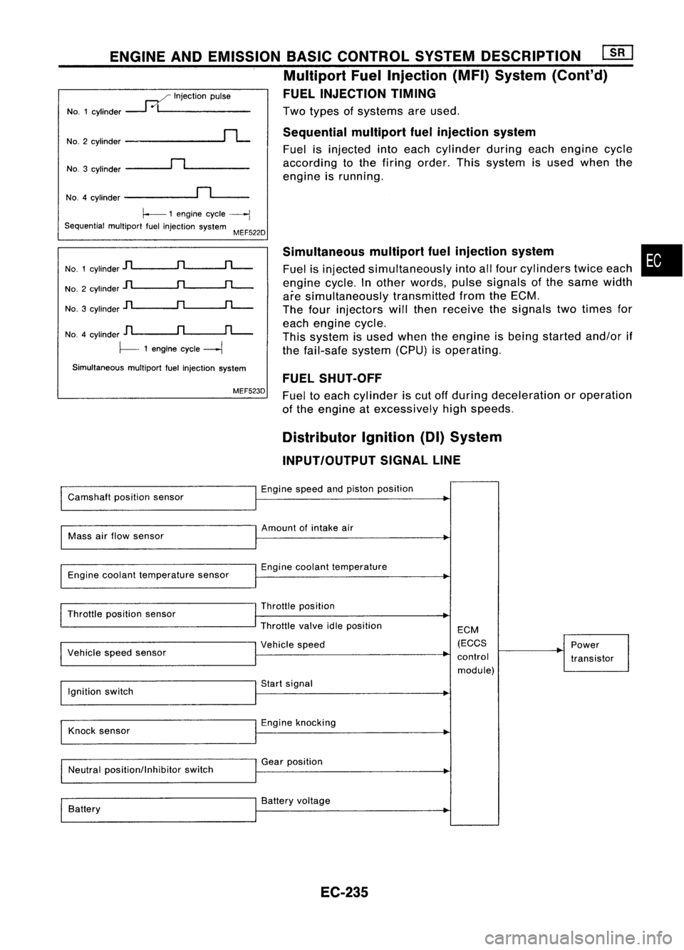
Twotypes ofsystems areused.
Sequential multiportfuelinjection system
Fuel isinjected intoeach cylinder duringeachengine cycle
according tothe firing order. Thissystem isused when the
engine isrunning.
ENGINE
ANDEMISSION BASICCONTROL SYSTEMDESCRIPTION ~
Multiport FuelInjection (MFI)System (Cont'd)
FUEL INJECTION TIMING
..--./ Injection pulse
NO.1 cylinder
---1
0/1 _
NO.3 cylinder
~n~ _
No.2
cylinder
rL
NO.4 cylinder
~n~_
~ 1engine cycle
----j
Sequential multiportfuelinjection system
MEF522D
No. 1cylinder
jl
n
rL-
No. 2cylinder
jl
n
rL-
No. 3cylinder
]l
n
rL-
NO.4 cylinder
D
n
fL-.
~- 1engine cycle
---1
Simultaneous multiportfuelinjection system
MEF523D Simultaneous
multipartfuelinjection system
Fuel isinjected simultaneously intoallfour cylinders twiceeach
engine cycle.Inother words, pulsesignals ofthe same width
are simultaneously transmittedfromtheECM.
The four injectors willthen receive thesignals twotimes for
each engine cycle.
This system isused when theengine isbeing started and/orif
the fail-safe system(CPU)isoperating.
FUEL SHUT-OFF
Fuel toeach cylinder iscut offduring deceleration oroperation
of the engine atexcessively highspeeds.
•
Distributor Ignition(DI)System
INPUT/OUTPUT SIGNALLINE
Camshaft positionsensor Engine
speedandpiston position
Mass airflow sensor Amount
ofintake air
Engine coolant temperature sensor Engine
coolant temperature
Throttle position sensor
I
Vehicle speedsensor Throttle
position
Throttle valveidleposition
I
Vehicle speed ECM
(ECCS
control module) Power
transistor
Ignition switch Start
signal
Knock sensor Engine
knocking
Neutral position/Inhibitor switchGear
position
Battery Battery
voltage
EC-235