Page 15 of 1701

DESCRIPTION
Shift Mechanism (Cont'd)
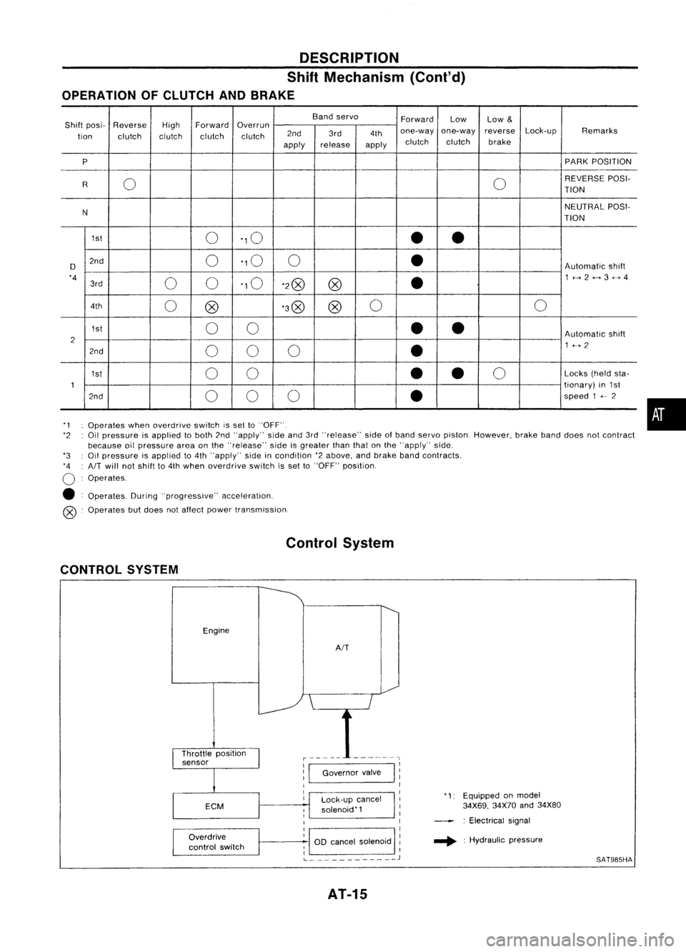
OPERATION OFCLUTCH ANDBRAKE
Bandservo
ForwardLow
Low
&
Shift posi- Reverse
HighForward
Overrun
Lock-upRemarks
tion clutch clutchclutchclutch 2nd
3rd4thone-way
one-way reverse
apply release
applyclutch
clutch brake
P PARK
POSITION
0 0REVERSE
POSI-
R TION
N NEUTRAL
POSI-
TION
1st 0'10
••
D 2nd
0'10
0
•
Automatic
shift
'4 00'10
'2@
@
•
1<-->2<-->3<-->4
3rd
4th 0@ '3@
@0
0
1st 00
••
Automatic
shift
2 1<-->2
2nd 00 0
•
1st 00
•
•
0
Locks
(heldsta-
1 tionary)
in1st
2nd 00 0
•
speed
1
<--
2
'1 Operates whenoverdrive switchissel to"OFF".
'2 Oilpressure isapplied toboth 2nd"apply" sideand3rd"release" sideofband servo piston. However, brakebanddoes notcontract
because oilpressure areaonthe "release" sideisgreater thanthatonthe "apply" side.
'3 Oilpressure isapplied to4th "apply" sideincondition '2above, andbrake bandcontracts.
'4 AIT
will notshift to4th when overdrive switchisset to"OFF" position.
o
Operates.
• Operates. During"progressive" acceleration.
@ Operates butdoes notaffect power transmission.
Control System
CONTROL SYSTEM
Engine
AIT
•
Lock-up cancel
solenoid'1
Overdrive
control switch
1:1
Governor valve
I
11
1
I
1
1
OD cancel solenoid :
; I
L
J
AT-15
'1:
Equipped onmodel
34X69, 34X70and34X80
: Electrical signal
.... :Hydraulic pressure
SAT985HA
Page 31 of 1701
ON-VEHICLESERVICE
SAT494HB
Model
34X68 Control
ValveAssembly andAccumulator
REMOVAL
1. Drain ATFfrom transaxle.
2. Remove oilpan andgasket.
3. Disconnect
AfT
solenoid harnessconnector.
4. Remove stopperringfrom
AfT
solenoid harnessterminal
body.
5. Pull out
AfT
solenoid harnessfromtransmission caseby
pushing terminal body.
AT-31
•
Page 38 of 1701
Converterhousingside(RHS)
Transmission caseside(LHS)
SAT259EA ON-VEHICLE
SERVICE
Differential SideOilSeal Replacement (Cont'd)
3. Install oilseals.
• Apply ATFtooil seal surface beforeinstalling.
Converter housing
side •
Install oilseals sothat dimensions
"A"
and
"8"
arewithin
specifications.
Transmission
case side
B
Oil
seal Oil
seal
A
SAT639D
A
5.5 -6.5 (0.217 -0.256)
4. Reinstall anypart removed.
AT-38
Unit:
mm(in)
B
0.5 (0.020)
or
less
Page 54 of 1701
DISASSEMBLV
21. Remove throttlewirefrom throttle lever.
22. Remove throttlewiremounting bolt.
23. Draw outthrottle wirefrom transmission case.
- All models -
24. Remove converter housingaccording tothe following pro-
cedures.
a. Remove converter housingmounting bolts@and
CID.
b. Remove converter housing.
c. Remove O-ringfromdifferential oilport.
AT-54
Page 55 of 1701
KV381054S0SAT030D
SAT132E
SAT840DB
SAT133E DISASSEMBL
V
25. Remove finaldrive assembly fromtransmission case.
• If
it is difficult to
lift
up byhand, tapfinal drive slightly with
a soft hammer (Exceptmodel34X81).
26. Remove differential sidebearing outerracefrom transmis-
sion case (Model 34X81).
27. Remove differential sidebearing adjusting shimfromtrans- •
mission case.
28. Remove differential sidebearing outerracefrom converter
housing (Model34X81).
29. Remove oilseal from converter housingusingascrew-
driver.
• Becareful nottodamage case.
AT-55
Page 56 of 1701
SAT134EDISASSEMBL
Y
30. Remove sideoilseal from transmission caseusing ascrew-
driver.
31. Remove oiltube from converter housing.
32. Remove oilpump according tothe following procedures.
a. Remove O-ringfrominput shaft.
b. Remove oilpump assembly fromtransmission case.
c. Remove thrustwasher andbearing racefrom oilpump
assembly.
AT-56
Page 65 of 1701
SAT070D
\LOW secondary weight
Low primary weight
Governor valve
High primary weight
High secondary weight
SAT071DDISASSEMBL
Y
53. Remove governor valveassembly according tothe follow-
ing procedures.
a. Remove snapringusing ascrewdriver.
b. Remove governor capusing water pumppliers.
c. Remove a-ringfromgovernor cap.
d. Remove governor valveassembly.
e. With lowprimary weightclosed, placetopofgovernor valve
assembly downtomake suregovernor valveproperly low-
ers under itsown weight.
f. Place topofgovernor assembly down.Operate bothlowand
high secondary weightstomake suregovernor valvefunc-
tions properly.
54. Remove sideoilseal from transmission caseusing ascrew-
driver.
• Becareful nottodamage case.
AT-55
•
Page 67 of 1701
REPAIRFORCOMPONENT PARTS
Manual ShaftandThrottle Lever(ConI'd)
4. Drive andthen pulloutparking rodplate retaining pin.
5. Remove parkingrodplate frommanual shaft.
6. Draw outparking rodfrom transmission case.
7. Pull outmanual shaftretaining pin. •
8. Remove manualshaftandmanual platefromtransmission
i
case.
9. Remove manualshaftoilseal.
SATOBOD
INSPECTION
• Check component partsforwear ordamage. Replaceif
necessary.
AT-67