Page 50 of 1701
DISASSEMBLY
J!in plug
1.
Drain ATFthrough drainplug.
SAT007D
2.Remove torqueconverter.
3. Check torque converter one-wayclutchusingcheck toolas
shown atleft.
a. Insert checktoolintothegroove ofbearing supportbuiltinto
one-way clutchouterrace.
b. While fixingbearing supportwithcheck tool,rotate one-way
clutch spline usingflat-bladed screwdriver.
c. Check innerracerotates clockwise only.Ifnot, replace
torque converter assembly.
/
SAT009D
One-way
clutch
~:e2
/ I
;,cr~~ar~ /
-
~
/
Bend awire anduse
it as acheck tool.
.----:-
Approx. 3.0(0.118)
[Bend a1.5 (0.059) die..
wire Inhall.]
Outer race
g
....
Unit: mm(in)
..
2
:
Approx.
15 (0.59)
4.Remove oilcharging pipeandoilcooler tube.
SAT586H AT-50
Page 163 of 1701
SAT620E
SAT586H
SAT428DA
Torque
converter
ASSEMBLY
Assembly 4(Cont'd)
14. Install inhibitor switch.
a. Set manual shaftin"P" position.
b. Temporarily installinhibitor switchonmanual shaft.
c.
Move
selector
lever
to"N" position.
d. Use a4mm (0.157 in)pin forthis adjustment.
1) Insert thepinstraight intothemanual shaftadjustment hole.
2) Rotate inhibitor switchuntilthepincan also beinserted
straight intohole ininhibitor switch.
e. Tighten inhibitor switchfixingbolts.
f. Remove pinfrom adjustment holeafter adjusting inhibitor
switch.
15. Install oilcharging pipeandoilcooler tubetotransmission •
case.
16. Install torque converter.
a. Pour ATFintotorque converter.
• Approximately 1liter (7/8Impqt)offluid isrequired fora
new torque converter.
• When reusing oldtorque converter, addthesame amount
of fluid aswas drained.
b. Install torque converter whilealigning notchesoftorque
converter withnotches ofoil pump.
AT-163
Page 373 of 1701

ELECTRICALSYSTEM
SECTION
EL
When youread wiring diagrams:
• Read GIsection, "HOWTOREAD WIRING DIAGRAMS".
When youperform troublediagnos.es, readGIsection, "HOWTOFOllOW FLOWCHART
IN TROUBLE DIAGNOSES" and"HOW TOPERFORM EFFICIENT DIAGNOSIS FORAN
ELECTRICAL INCIDENT".
CONTENTS
PRECAUTIONS 4
Supplemental RestraintSystem(SRS)"AIR
BAG" (DualAirBag System) 4
Supplemental RestraintSystem(SRS)"AIR
BAG" (Single AirBag System) 4
HARNESS CONNECTOR 5
Description 5
STANDARDIZED RELAy 6
Description 6
POWER SUPPLY ROUTING 8
Schematic 8
Wiring Diagram -POWER - 10
Fuse 19
Fusible Link 19
Circuit Breaker 19
GROUND DISTRIBUTION 20
BATTERy 25
How toHandle Battery 25
Battery TestandCharging Chart.. 28
Service DataandSpecifications (SOS) 32
STARTING SySTEM
33
Wiring Diagram -START - 33
Trouble Diagnoses 35
Construction 36
Removal andInstallation .45
Magnetic SwitchCheck .46
Pinion/Clutch Check 46
Brush Check 46
Yoke Check 47
Armature Check 48
Assembly .49
Service DataandSpecifications (SDS) 50
CHARGING SYSTEM 52
Wiring Diagram -CHARGE - 52
Trouble Diagnoses 54Construction
55
Removal andInstallation 57
Disassembly 57
Rotor Check 57
Brush Check 58
Stator Check 58
Diode Check 59
Assembly 60
Service DataandSpecifications (SDS) 61
COMBINATION SWITCH 62
Combination Switch/Check 62
Replacement 64
HEADLAMP -Without Daytime lightSystem -65
Wiring Diagram -H/LAMP - 65
Trouble Diagnoses 67
HEADLAMP -Daytime lightSystem - 68
Operation (Daytimelightsystem) 68
System Description 69
Schematic 70
Wiring Diagram -DTRL - 71
Trouble Diagnoses (DaytimeLight) 74
HEADLAMP 75
Bulb Replacement... 75•
Aiming Adjustment. 75
HEADLAMP -Headlamp Aiming
Control- 77
Wiring Diagram -AIM - 77
Description 81
EXTERIOR LAMP 82
Clearance, LicenseandTail Lamps/Schematic 82
Clearance, LicenseandTail Lamps/Wiring
Diagram -TAILIL - 83
Stop Lamp/Wiring Diagram-STOP/L - 92
Back-up Lamp/Wiring Diagram-BACK/L -94
Front FogLamp/Wiring Diagram-F/FOG -96
Front FogLamp BulbReplacement 101
Page 397 of 1701

SEL711EBATTERY
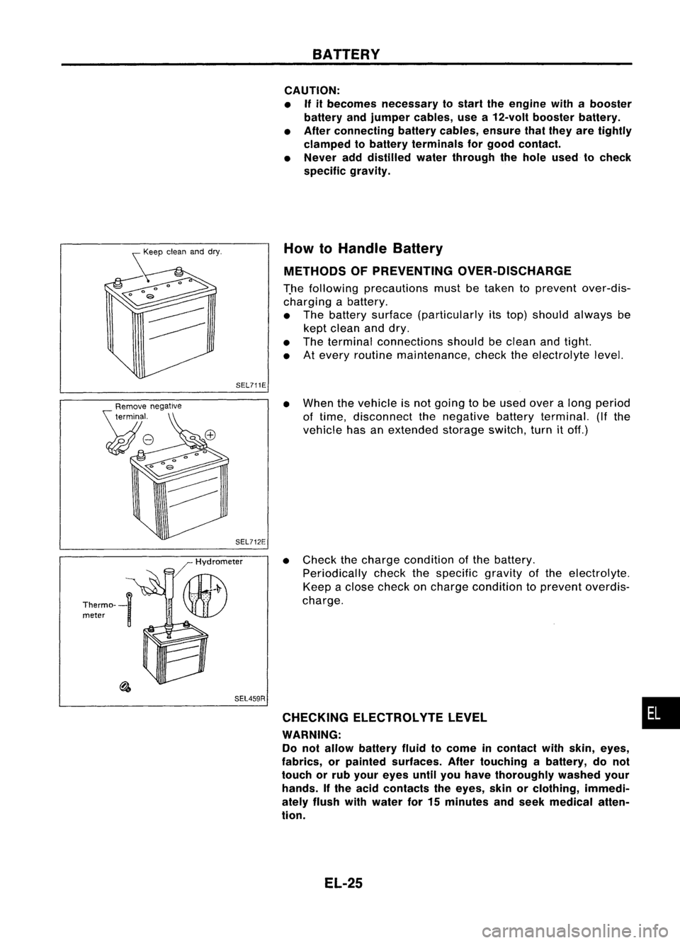
CAUTION:
• If
itbecomes necessary tostart theengine withabooster
battery andjumper cables, usea12-volt booster battery.
• After connecting batterycables, ensurethatthey aretightly
clamped tobattery terminals forgood contact.
• Never adddistilled waterthrough thehole used tocheck
specific gravity.
How toHandle Battery
METHODS OFPREVENTING OVER-DISCHARGE
T.he following precautions mustbetaken toprevent over-dis-
charging abattery.
• The battery surface (particularly itstop) should always be
kept clean anddry.
• The terminal connections shouldbeclean andtight.
• Atevery routine maintenance, checktheelectrolyte level.
SEL459R
•
When thevehicle isnot going tobe used overalong period
of time, disconnect thenegative batteryterminal. (Ifthe
vehicle hasanextended storageswitch,turnitoff.)
• Check thecharge condition ofthe battery.
Periodically checkthespecific gravityofthe electrolyte.
Keep aclose check oncharge condition toprevent overdis-
charge.
CHECKING ELECTROLVTELEVEL •
WARNING: Do not allow battery fluidtocome incontact withskin, eyes,
fabrics, orpainted surfaces. Aftertouching abattery, donot
touch orrub your eyes untilyouhave thoroughly washedyour
hands. Ifthe acid contacts theeyes, skinorclothing, immedi-
ately flush withwater for15minutes andseek medical atten-
tion.
EL-25
Page 398 of 1701
BATTERY
How
10
Handle Battery (Coni'd)
• Remove thecell plug using asuitable tool.
• Add distilled wateruptothe MAX level.
SEL001K
Duration ofcharge
SULPHATION
A battery willbecompletely discharged ifit is left unattended
for along time andthespecific gravitybecomes lessthan 1.100.
This mayresult insulphation onthe cell plates.
To find ifa discharged batteryhasbeen "sulphated", payatten-
tion toits voltage andcurrent whencharging it.As shown inthe
figure atleft, ifthe battery hasbeen "sulphated", lesscurrent
and higher voltage maybeobserved inthe initial stage of
charging.
Charging
voltage
Normal
battery
SUlphated battery
, Charging current
Charging
voltage~_"'"-----
t~
Charging current
t
SEL005Z
Read toplevel
with scale
Hydrometer
Thermal~n gauge ]/
Hydrometer
II~
.' \U)
SEL442DSPECIFIC
GRAVITYCHECK
1. Read hydrometer andthermometer indicationsateye level.
• When electrolyte levelistoo low, tiltbattery casetoraise it
for easy measurement.
SEL006Z
EL-26
Page 400 of 1701

ChartI
BATTERY
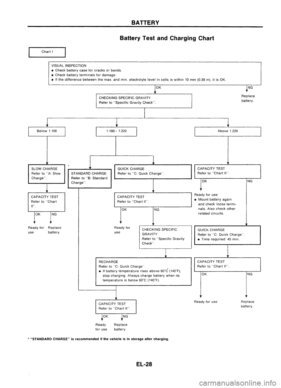
Battery TestandCharging Chart
VISUAL INSPECTION
• Check battery caseforcracks orbends .
• Check battery terminals fordamage .
• Ifthe difference betweenthemax. andmin. electrolyte levelincells iswithin 10mm (0.39 in),itis OK.
OK
t
NG
CHECKING SPECIFICGRAVITY Replace
Refer to"Specific GravityCheck". battery.
I
Below 1.100
1.100-1.220 Above1.220
.
SLOW CHARGE QUICKCHARGE CAPACITY
TEST
Refer to"A: Slow STANDARD CHARGE Referto"C: Quick Charge". Refer
to"Chart II".
Charge". Referto"B: Standard
r
K
Charge".
NG
CAPACITY TEST CAPACITYTEST Ready
foruse
Refer to"Chart Refer
to"Chart II". •
Mount battery again
II". and
check loosetermi-
OK NG nals.
Alsocheck other
t
K
t
G
related
circuits.
Ready forReplace Readyfor
CHECKING SPECIFIC
QUICKCHARGE
use battery. use
GRAVITY Referto"C: Quick Charge".
Refer to"Specific Gravity
•Time required: 45min.
Check".
1
RECHARGE CAPACITY
TEST
Refer to"C: Quick Charge" . Refer
to"Chart II".
• Ifbattery temperature risesabove 60°C(140°F),
stop charging. Alwayscharge batterywhenits OK
NG
temperature isbelow 60°C(140°F).
CAPACITY TEST Ready
foruse Replace
Refer to"Chart II" battery.
t
OK
t
NG
Ready
for use Replace
battery.
*
"STANDARD CHARGE"isrecommended
if
the vehicle isin storage altercharging.
EL-28
Page 401 of 1701
CAPACITYTEST BATTERY
Battery TestandCharging Chart(Cont'd)
• Check battery typeanddetermine thespecified current
using thefollowing table.
Fig. 1DISCHARGING CURRENT
(Load Tester)
~m o~
Type
Current
(A)
28B19R(L) 90
34B19R(L) 99
46B24R(L) 135
55B24R(L) 135
50D23R(L) 150
55D23R(L) 180
65D26R(L) 195
80D26R(L) 195
75D31R(L) 210
95D31R(L) 240
115D31R(L) 240
95E41R(L) 300
130E41R(L) 330
Test
using loadtester.
OK NG
Read
loadtester voltage
when specified discharging
current (RefertoFig~ 1.)
flows through batteryfor15
seconds.
Above 9.6 Below9.6
volts volts
Ready foruse Gotonext
step.
Chart
II
OK NG
Follow
manufacturer's
instructions tocheck and
determine ifbattery isser-
viceable,
Ready foruse Gotonext
step.
SEL008Z
•
EL-29
Page 402 of 1701

BATTERY
Battery TestandCharging Chart(Cont'd)
I
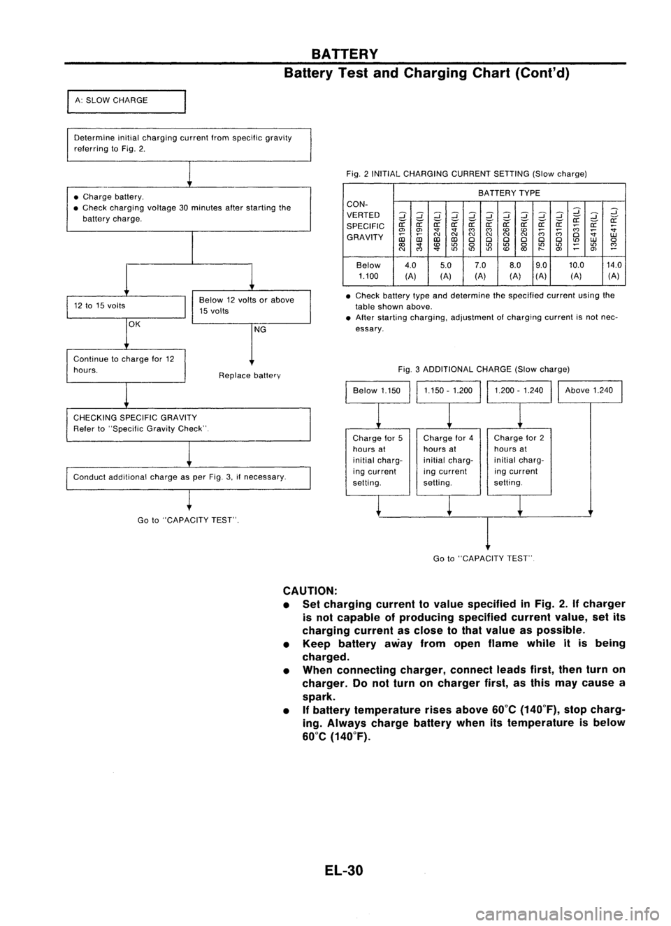
A: SLOW CHARGE
Determine initialcharging currentIromspecilic gravity
relerring toFig. 2.
Fig.2INITIAL CHARGING CURRENTSETTING(Slowcharge)
• Charge battery.
• Check charging voltage30minutes afterstarting the
battery charge. BATTERY
TYPE
CON-
VERTED
2
::J
2
::J
::J
2
::J
2
::J
::J
2
2
::J
if ifif if if
r:r:
if
SPECIFIC
r:r:
r:r: r:r:r:r:r:r:
;;;
r:r:
:;
en en
'
""""
;;;;;;
:;
GRAVITY
~
NNN
NN
N
0
1.U
CD CDCDCD
000 000
to
1.U
0
<0
'
to
0
to
LO
0
LOLO
~
LO
""
N
""
'
toto
LO
<0
"-
en
~
en
~
Below 4.0
5.07.0
8.09.0 10.0
14.0
1.100 (A)(A)(A) (A)(A)
(A) (A)
• Check battery typeanddetermine thespecified currentusingthe
table shown above.
• After starting charging, adjustment ofcharging currentisnot nec-
essary.
Conduct additional chargeasper Fig. 3.ifnecessary. Fig.
3ADDITIONAL CHARGE(Slowcharge)
Continue
tocharge lor12
hours.
CHECKING SPECIFICGRAVITY
Reier to"Specilic GravityCheck". Replace
battery
Chargefor5
hours at
initial charg-
ing current
selting. Charge
lor4
hours at
initial charg-
ing current
setting. Charge
lor2
hours at
initial charg-
ing current
setting. Above
1.240
Go to"CAPACITY TEST".
I
Go to"CAPACITY TEST"
CAUTION:
• Set charging currenttovalue specified inFig. 2.
If
charger
is not capable ofproducing specifiedcurrentvalue,setits
charging currentasclose tothat value aspossible.
• Keep battery awayfromopen flame whileitis being
charged.
• When connecting charger,connectleadsfirst,thenturnon
charger. Donot turn oncharger first,asthis may cause a
spark.
• If
battery temperature risesabove 60°C(140°F), stopcharg-
ing. Always chargebatterywhenitstemperature isbelow
60°C (140°F).
EL-30