Page 1406 of 1701
PRECAUTIONSANDPREPARATION
Precautions forRefrigerant Connection
WARNING: Make sureallrefrigerant isdischarged intotherecycling equipment andthepressure inthe system is
less than atmospheric pressure.Thengradually loosenthedischarge sidehose fitting andremove it.
CAUTION:
When replacing orcleaning refrigerant cyclecomponents, observethefollowing.
• When thecompressor isremoved, storeitin the same position asitis when mounted onthe car.
Failure todo sowill cause lubricant toenter thelow pressure chamber.
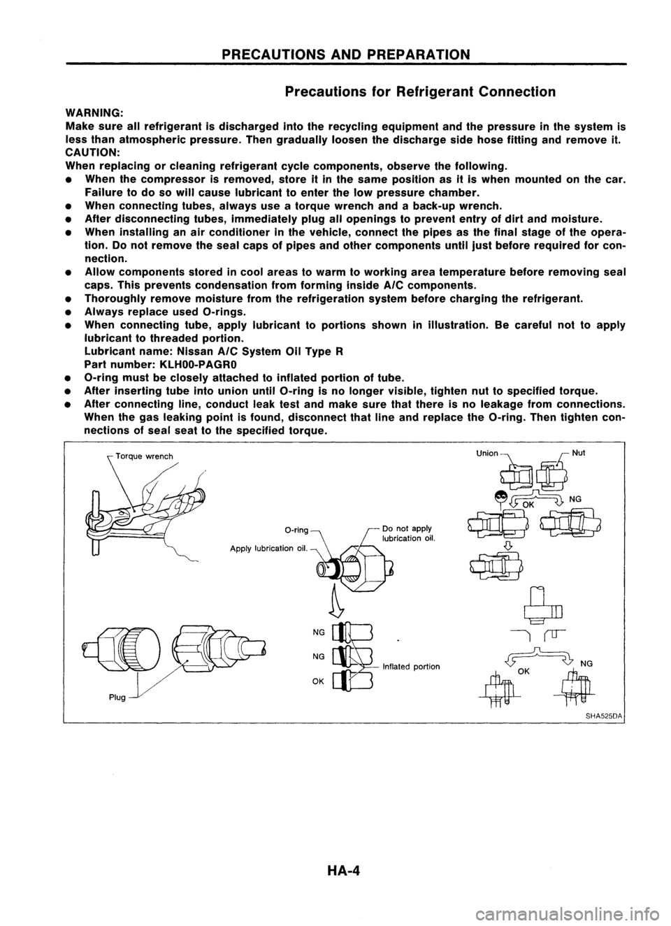
• When connecting tubes,always useatorque wrench andaback-up wrench.
• After disconnecting tubes,immediately plugallopenings toprevent entryofdirt and moisture.
• When installing anair conditioner inthe vehicle, connect thepipes asthe final stage ofthe opera-
tion. Donot remove theseal caps ofpipes andother components untiljustbefore required forcon-
nection.
• Allow components storedincool areas towarm toworking areatemperature beforeremoving seal
caps. Thisprevents condensation fromforming inside
AIC
components.
• Thoroughly removemoisture fromtherefrigeration systembeforecharging therefrigerant.
• Always replace usedO-rings.
• When connecting tube,apply lubricant toportions showninillustration. Becareful nottoapply
lubricant tothreaded portion.
Lubricant name:Nissan
AIC
System OilType R
Part number: KLHOO-PAGRO
• O-ring mustbeclosely attached toinflated portionoftube.
• After inserting tubeintounion untilO-ring isno longer visible, tightennuttospecified torque.
• After connecting line,conduct leaktestand make surethatthere isno leakage fromconnections.
When thegas leaking pointisfound, disconnect thatlineand replace theO-ring. Thentighten con-
nections ofseal seattothe specified torque.
O-ring
Apply lubrication oil.
NG
NG
OK -
Inflated portion
SHA525DA
HA-4
Page 1408 of 1701
PRECAUTIONSANDPREPARATION
Special Service Tools(Cont'd)
CR-14 compressor
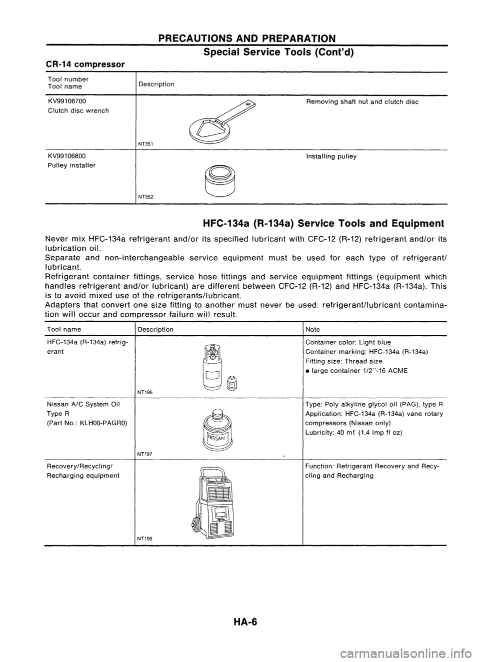
Tool number
Tool name
KV99106700
Clutch discwrench
KV991 06800
Pulley installer Description
NT351
NT352
Removing
shaftnutand clutch disc
Installing pulley
HFC-134a (R-134a)ServiceToolsandEquipment
Never mixHFC-134a refrigerant and/oritsspecified lubricantwithCFC-12 (R-12)refrigerant and/orits
lubrication oil.
Separate andnon-interchangeable serviceequipment mustbeused foreach typeofrefrigerant/
lubricant.
Refrigerant containerfittings,servicehosefittings andservice equipment fittings(equipment which
handles refrigerant and/orlubricant) aredifferent between CFC-12(R-12)andHFC-134a (R-134a).This
is to avoid mixed useofthe refrigerants/lubricant.
Adapters thatconvert onesize fitting toanother mustnever beused: refrigerant/lubricant contamina-
tion willoccur andcompressor failurewillresult.
Tool name
Description Note
HFC-134a (R-134a)refrig-
~~
Container
color:Lightblue
erant Containermarking:HFC-134a (R-134a)
Fitting size:Thread size
• large contai ner1/2"-16 ACME
NT196
Nissan A/CSystem Oil Type:Polyalkyline glycoloil(pAG), typeR
Type R
~
Application:
HFC-134a(R-134a)vanerotary
(Part No.:KLHOO-PAGRO)
compressors(Nissanonly)
Lubricity: 40me (1.4 Imp
fI
oz)
NT197
Recovery/Recycling/
~
Function:
Refrigerant RecoveryandRecy-
Recharging equipment
":'s
Q"'~
cling
andRecharging
==
•
~ t:J
~
II
NT195
HA-6
Page 1410 of 1701
PRECAUTIONSANDPREPARATION
Precautions forService Equipment
RECOVERY/RECYCLING/RECHARGING EQUIPMENT
Be certain tofollow themanufacturers instructionsformachine
operation andmachine maintenance. Neverintroduce any
refrigerant otherthanthatspecified intothemachine.
ELECTRONIC LEAKDETECTOR
Be certain tofollow themanufactures instructionsfortester
operation andtester maintenance.
With isolator valve
Without isolatorvalve
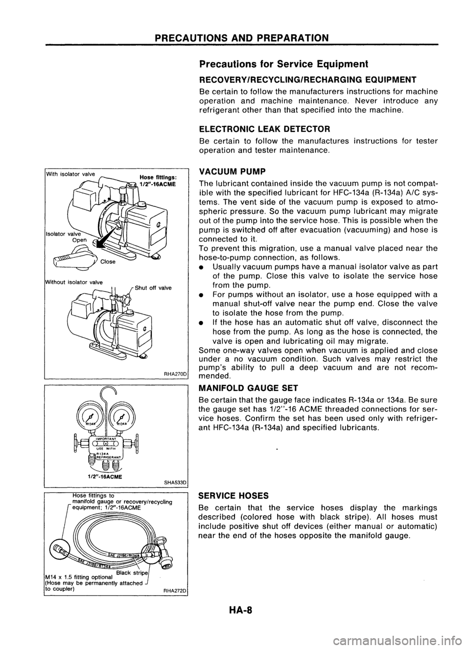
VACUUM
PUMP
Hose fittings:
1/2".16ACME
Thelubricant contained insidethevacuum pumpisnot compat-
ible with thespecified lubricantforHFC-134a (R-134a)
AIC
sys-
tems. Thevent sideofthe vacuum pumpisexposed toatmo-
spheric pressure. Sothe vacuum pumplubricant maymigrate
out ofthe pump intotheservice hose.Thisispossible whenthe
pump isswitched offafter evacuation (vacuuming) andhose is
connected toit.
To prevent thismigration, useamanual valveplaced nearthe
hose-to-pump connection,asfollows.
• Usually vacuum pumpshaveamanual isolatorvalveaspart
of the pump. Closethisvalve toisolate theservice hose
from thepump.
• For pumps without anisolator, useahose equipped witha
manual shut-off valvenearthepump end.Close thevalve
to isolate thehose fromthepump.
• Ifthe hose hasanautomatic shutoffvalve, disconnect the
hose fromthepump. Aslong asthe hose isconnected, the
valve isopen andlubricating oilmay migrate.
Some one-way valvesopenwhen vacuum isapplied andclose
under ano vacuum condition. Suchvalves mayrestrict the
pump's abilitytopull adeep vacuum andarenotrecom-
RHA270D
mended.
MANIFOLD GAUGESET
Be certain thatthegauge faceindicates R-134aor134a. Besure
the gauge sethas
1/2"-16
ACMEthreaded connections forser-
vice hoses. Confirm theset has been usedonlywith refriger-
ant HFC-134a (R-134a)andspecified lubricants.
~
1f2"-16ACME
SHA533D
Hose fittings to
manifold gaugeorrecovery/recycling
equipment; 1/2"-16ACME
RHA272DSERVICE
HOSES
Be certain thattheservice hosesdisplay themarkings
described (coloredhosewithblack stripe). Allhoses must
include positive shutoffdevices (eithermanual orautomatic)
near theend ofthe hoses opposite themanifold gauge.
HA-8
Page 1411 of 1701
Open
Close
AIC
service valve
Counterclockwise
Clockwise
Shut
offvalve rotation
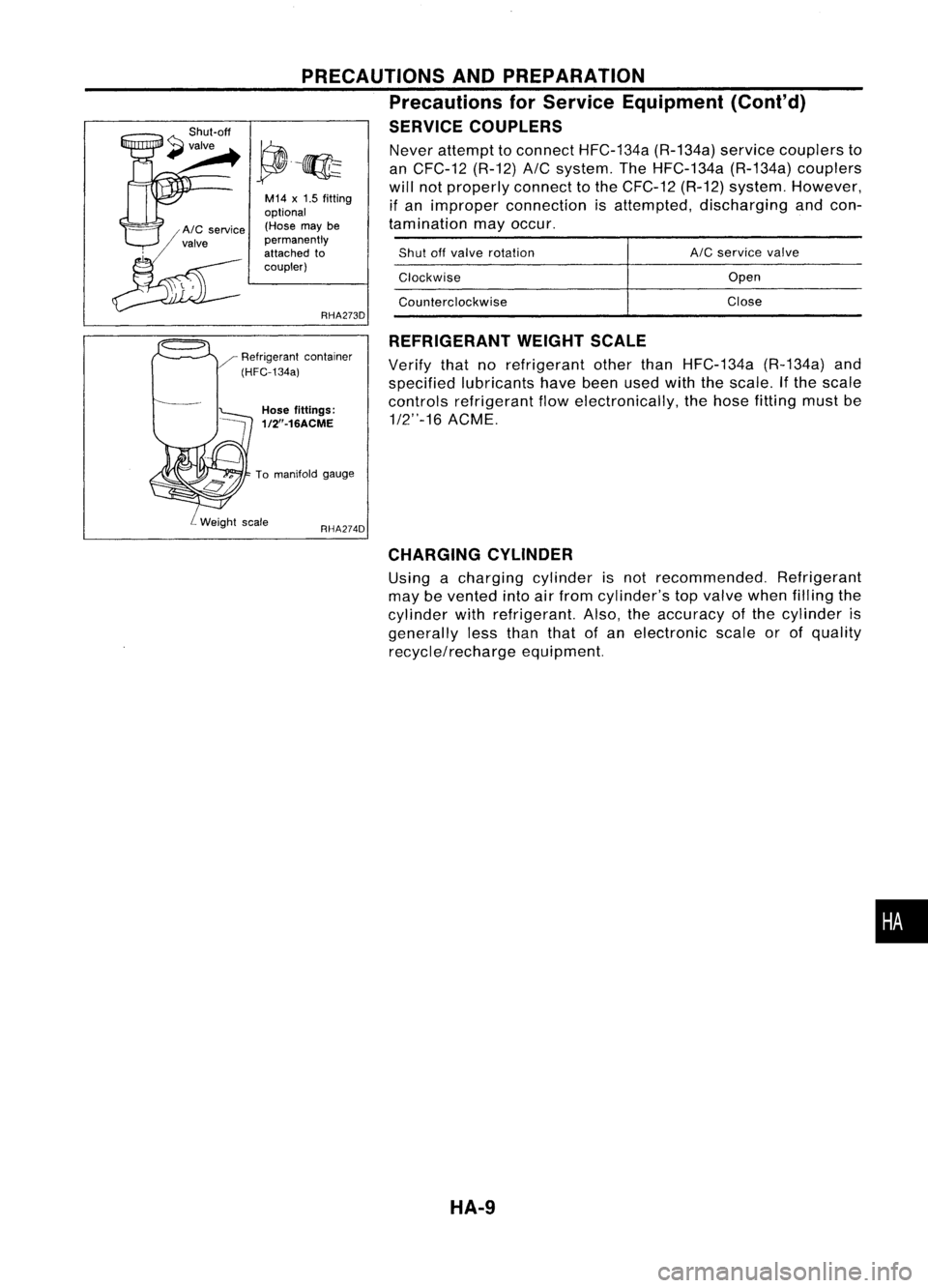
Never
attempt toconnect HFC-134a (R-134a)servicecouplers to
an CFC-12 (R-12)
A/C
system. TheHFC-134a (R-134a)couplers
will notproperly connecttothe CFC-12 (R-12)system. However,
if an improper connection isattempted, discharging andcon-
tamination mayoccur.
REFRIGERANT WEIGHTSCALE
Verify thatnorefrigerant otherthanHFC-134a (R-134a)and
specified lubricants havebeenusedwiththescale. Ifthe scale
controls refrigerant flowelectronically, thehose fitting mustbe
1/2"-16 ACME.
RHA274D
PRECAUTIONS
ANDPREPARATION
Precautions forService Equipment (Cont'd)
SERVICE COUPLERS
RHA273D
M14
x
1.5 fitting
optional (Hose maybe
permanently
attached to
coupler)
Hose fittings:
1/2"-16ACME
To manifold gauge
CHARGING CYLINDER
Using acharging cylinderisnot recommended. Refrigerant
may bevented intoairfrom cylinder's topvalve whenfilling the
cylinder withrefrigerant. Also,theaccuracy ofthe cylinder is
generally lessthan thatofan electronic scaleorofquality
recycle/recharge equipment.
•
HA-9
Page 1412 of 1701
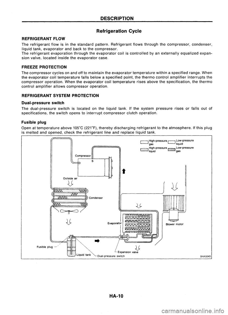
DESCRIPTION
Refrigeration Cycle
REFRIGERANT FLOW
The refrigerant flowisinthe standard pattern.Refrigerant flowsthrough thecompressor, condenser,
liquid tank,evaporator andback tothe compressor.
The refrigerant evaporation throughtheevaporator coiliscontrolled byan externally equalizedexpan-
sion valve, located insidetheevaporator case.
FREEZE PROTECTION
The compressor cyclesonand offtomaintain theevaporator temperature withinaspecified range.When
the evaporator coiltemperature fallsbelow aspecified point,thethermo controlamplifier interrupts the
compressor operation.Whentheevaporator coiltemperature risesabove thespecification, thethermo
control amplifier allowscompressor operation.
REFRIGERANT SYSTEMPROTECTION
Dual-pressure switch
The dual-pressure switchislocated onthe liquid tank.Ifthe system pressure risesorfalls outof
specifications, theswitch openstointerrupt compressor clutchoperation.
Fusible plug
Open attemperature above105°C(221°F), thereby discharging refrigeranttothe atmosphere. Ifthis plug
is melted andopened, checktherefrigerant lineand replace liquidtank.
c:::::.J
High-pressure
EJ
Low-pressure
gas liquid
1:-:-:-:-::-:-::-:-:1
~~~~pressure
!::i'i'i':}':J
~~:-pressure
Compressor
D
Outside air
U
s
t
Fusible plug-~
~..
U
'" Expansionvalve
Liquid tank"'--Dual-pressure switch
HA-10
Blower
motor
SHA504D
Page 1468 of 1701
SERVICEPROCEDURES
HFC-134a (R-134a)ServiceProcedure
SETTING OFSERVICE TOOLSANDEQUIPMENT
DISCHARGING REFRIGERANT
WARNING:
Avoid breathing
A/C
refrigerant andlubricant vaporormist. Exposure mayirritate eyes,noseandthroat.
Remove HFC-134a (R-134a)from
A/C
system usingcertified serviceequipment meetingrequirements
of HFC-134a (R-134a)recycling equipment orHFC-134a (R-134a)recovery equipment. Ifaccidental sys-
tem discharge occurs,ventilate workareabefore resuming service.Additional healthandsafety infor-
mation maybeobtained fromrefrigerant andlubricant manufacturers.
Example
I-,
V ~I~e service
I~ ~
..
_----~
Recovery/Recycling/Recharging equipment
SHA539DC
EVACUATING SYSTEMANDCHARGING REFRIGERANT
Example
Preferred (Best)method Alternate
method
Manifoldgaugeset
SHA540DC
HA-66
Page 1469 of 1701
Recoveredlubricant(HA-68)
SERVICE
PROCEDURES
HFC-134a (R-134a)ServiceProcedure (Cont'd)
Set therecoverylrecycling equip-
ment.
Discharge refrigerant into
recoveryl
recycling equipment.
Repair orreplace parts.
Evacuate theunwanted airincharg-
ing hoses.
Evacuating (over25minutes).
Check airtightness.
I
Partial charging
[approx. 200g(7.05 oz)J.
'-1
Repair.
Preliminary refrigerantleakcheck.
,-1
Complete charging[specified
amount -200 g(7.05 oz)J. Repair.
'-2
---C-h-e-c-k-f-o-r -re-f-r-ig-e-r-a-nt-Ie-a-k-s-.
--H
Repair.
--r.---~. '---.---
Check for
AIC
operation and
AIC
cooling performance
Remove servicecouplers from
AIC
service valves.
Recover refrigerant incharging
hoses.
Remove servicetools.
Note: '-1Before charging refrigerant, ensureengineisoff.
'-2 Before checking forleaks, startengine toactivate airconditioning systemthenturnitoff.
Service valvecapsmustbeattached tovalves (toprevent leakage).
HA-67
•
Page 1471 of 1701
SERVICEPROCEDURES
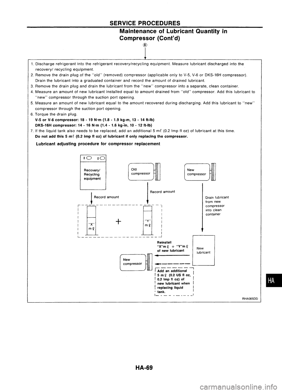
Maintenance ofLubricant Quantityin
Compressor (Cont'd)
@
1. Discharge refrigerant intotherefrigerant recovery/recycling equipment.Measurelubricantdischarged intothe
recovery/ recyclingequipment.
2. Remove thedrain plugofthe "old" (removed) compressor (applicableonlytoV-5, V-6orDKS-16H compressor).
Drain thelubricant intoagraduated containerandrecord theamount ofdrained lubricant.
3. Remove thedrain pluganddrain thelubricant fromthe"new" compressor intoaseparate, cleancontainer.
4. Measure anamount ofnew lubricant installedequaltoamount drained from"old" compressor. Addthislubricant to
"new" compressor throughthesuction portopening.
5. Measure anamount ofnew lubricant equaltothe amount recovered duringdischarging. Addthislubricant to"new"
compressor throughthesuction portopening.
6. Torque thedrain plug.
V.5 orV-6 compressor: 18-19 N'm (1.8-1.9 kg-m, 13-14 ft-Ib)
DKS.16H compressor: 14-16 N'm (1.4-1.6 kg-in, 10-12 ft-Ib)
7. Ifthe liquid tankalso needs tobe replaced, addanadditional 5mC (0.2 Imp IIoz) oflubricant atthis time.
Do not add this5m C(0.2 ImpIIoz) oflubricant ifonly replacing thecompressor.
Lubricant adjustingprocedure forcompressor replacement
DO DO
Oldcompressor
Recovery/
Recycling
eqUipment
!
Roo'"
,m,,",
1
R,,,,'
,moo",
,--------------------,
I I
I I
I + I
I "Y"I
I "X"
mQ
I
I
mQ
I
I I
L ~
New
compressor
Drainlubricant
from new
compressor
into clean
container
------ L-...
.J
New
compressor
HA-69
Reinstall
"X"m
Q
+
"Y"m
Q
of new lubricant
-.-------
fAdda;-addition;;
"I
15m
Q
(0.2 USfl
Ol,
I 0.2
Imp
fl
Ol)
of
I
I new lubricant when
I
!
replacing liquid I
, tank. I
1- -__ I
New
lubricant
RHA065DD
•